EP1512376B1 - Strahlentomographievorrichtung und Strahlentomographieverfahren - Google Patents
Strahlentomographievorrichtung und Strahlentomographieverfahren Download PDFInfo
- Publication number
- EP1512376B1 EP1512376B1 EP04255382A EP04255382A EP1512376B1 EP 1512376 B1 EP1512376 B1 EP 1512376B1 EP 04255382 A EP04255382 A EP 04255382A EP 04255382 A EP04255382 A EP 04255382A EP 1512376 B1 EP1512376 B1 EP 1512376B1
- Authority
- EP
- European Patent Office
- Prior art keywords
- radiation
- detection
- data
- ray
- detection data
- Prior art date
- Legal status (The legal status is an assumption and is not a legal conclusion. Google has not performed a legal analysis and makes no representation as to the accuracy of the status listed.)
- Expired - Lifetime
Links
- 230000005855 radiation Effects 0.000 title claims description 150
- 238000003325 tomography Methods 0.000 title claims description 33
- 238000000034 method Methods 0.000 title claims description 23
- 238000001514 detection method Methods 0.000 claims description 306
- 238000003384 imaging method Methods 0.000 claims description 39
- 230000001678 irradiating effect Effects 0.000 claims description 11
- 230000008569 process Effects 0.000 claims description 10
- 238000002591 computed tomography Methods 0.000 description 19
- 238000010586 diagram Methods 0.000 description 19
- 230000000007 visual effect Effects 0.000 description 6
- 230000009467 reduction Effects 0.000 description 5
- MARUHZGHZWCEQU-UHFFFAOYSA-N 5-phenyl-2h-tetrazole Chemical compound C1=CC=CC=C1C1=NNN=N1 MARUHZGHZWCEQU-UHFFFAOYSA-N 0.000 description 2
- 238000003491 array Methods 0.000 description 2
- 230000006866 deterioration Effects 0.000 description 2
- 238000002203 pretreatment Methods 0.000 description 2
- 230000004044 response Effects 0.000 description 2
- 230000035945 sensitivity Effects 0.000 description 2
- 230000008859 change Effects 0.000 description 1
- 230000000694 effects Effects 0.000 description 1
- 238000001914 filtration Methods 0.000 description 1
- 230000006872 improvement Effects 0.000 description 1
- 238000004519 manufacturing process Methods 0.000 description 1
- 238000012986 modification Methods 0.000 description 1
- 230000004048 modification Effects 0.000 description 1
- 239000004065 semiconductor Substances 0.000 description 1
- 229910052724 xenon Inorganic materials 0.000 description 1
- FHNFHKCVQCLJFQ-UHFFFAOYSA-N xenon atom Chemical compound [Xe] FHNFHKCVQCLJFQ-UHFFFAOYSA-N 0.000 description 1
Images




Classifications
-
- A—HUMAN NECESSITIES
- A61—MEDICAL OR VETERINARY SCIENCE; HYGIENE
- A61B—DIAGNOSIS; SURGERY; IDENTIFICATION
- A61B6/00—Apparatus or devices for radiation diagnosis; Apparatus or devices for radiation diagnosis combined with radiation therapy equipment
- A61B6/02—Arrangements for diagnosis sequentially in different planes; Stereoscopic radiation diagnosis
- A61B6/03—Computed tomography [CT]
-
- A—HUMAN NECESSITIES
- A61—MEDICAL OR VETERINARY SCIENCE; HYGIENE
- A61B—DIAGNOSIS; SURGERY; IDENTIFICATION
- A61B6/00—Apparatus or devices for radiation diagnosis; Apparatus or devices for radiation diagnosis combined with radiation therapy equipment
- A61B6/02—Arrangements for diagnosis sequentially in different planes; Stereoscopic radiation diagnosis
- A61B6/03—Computed tomography [CT]
- A61B6/032—Transmission computed tomography [CT]
-
- G—PHYSICS
- G01—MEASURING; TESTING
- G01N—INVESTIGATING OR ANALYSING MATERIALS BY DETERMINING THEIR CHEMICAL OR PHYSICAL PROPERTIES
- G01N23/00—Investigating or analysing materials by the use of wave or particle radiation, e.g. X-rays or neutrons, not covered by groups G01N3/00 – G01N17/00, G01N21/00 or G01N22/00
- G01N23/02—Investigating or analysing materials by the use of wave or particle radiation, e.g. X-rays or neutrons, not covered by groups G01N3/00 – G01N17/00, G01N21/00 or G01N22/00 by transmitting the radiation through the material
- G01N23/04—Investigating or analysing materials by the use of wave or particle radiation, e.g. X-rays or neutrons, not covered by groups G01N3/00 – G01N17/00, G01N21/00 or G01N22/00 by transmitting the radiation through the material and forming images of the material
- G01N23/046—Investigating or analysing materials by the use of wave or particle radiation, e.g. X-rays or neutrons, not covered by groups G01N3/00 – G01N17/00, G01N21/00 or G01N22/00 by transmitting the radiation through the material and forming images of the material using tomography, e.g. computed tomography [CT]
-
- G—PHYSICS
- G01—MEASURING; TESTING
- G01N—INVESTIGATING OR ANALYSING MATERIALS BY DETERMINING THEIR CHEMICAL OR PHYSICAL PROPERTIES
- G01N2223/00—Investigating materials by wave or particle radiation
- G01N2223/40—Imaging
- G01N2223/419—Imaging computed tomograph
-
- G—PHYSICS
- G01—MEASURING; TESTING
- G01N—INVESTIGATING OR ANALYSING MATERIALS BY DETERMINING THEIR CHEMICAL OR PHYSICAL PROPERTIES
- G01N2223/00—Investigating materials by wave or particle radiation
- G01N2223/60—Specific applications or type of materials
- G01N2223/612—Specific applications or type of materials biological material
Definitions
- the present invention relates to a radiation tomography apparatus and a radiation tomography method thereof.
- An X-ray CT (Computed Tomography) apparatus that generates an image of a tomographic plane of a subject to be imaged using an X-ray corresponding to radiation has been known as a radiation tomography apparatus.
- the X-ray CT apparatus has been used in widespread applications such as medical and industrial applications with a human body and an object as subjects to be imaged.
- the X-ray CT apparatus scans the periphery of a subject to be imaged with a subject's body axis direction as the axis and applies X-rays to the subject from a plurality of view directions through an X-ray tube.
- the X-rays radiated from the X-ray tube are blocked or cut off thereby forming an X-ray so as to be applied to an imaging area of the subject.
- the X-rays transmitted through the subject from the plural view directions via the collimator are detected by an X-ray detector array every their view directions, and a tomographic image corresponding to the imaging area of the subject is reconstructed and generated based on detection data generated by the X-rays detected by the X-ray detector array.
- the X-ray CT apparatus has an X-ray detector array in which a plurality of X-ray detection elements are arranged in array form so as to be capable of obtaining a plurality of tomographic images while the periphery of the subject is being scanned with one rotation.
- the X-ray detector array has X-ray detection modules in which X-ray detection elements for detecting an X-ray are arranged plural in array form.
- a plurality of X-ray detection modules are configured so as to be disposed adjacent to both a channel direction and a body axial direction.
- the plurality of X-ray detection elements are disposed adjacent to one another in the X-ray detector array in which the plurality of X-ray detection elements are arranged in array form, crosstalk might occur among the X-ray detection elements due to a detected X-ray. Therefore, when a tomographic image is reconstructed and generated based on detection data containing the crosstalk, there might be cases where in the X-ray CT apparatus, a reduction in the contrast of a tomographic image and artifacts occurred and the quality of an image was deteriorated.
- the generated amounts of crosstalk are determined every X-ray detection elements in advance, and detection data are corrected using the determined generated amounts of crosstalk (refer to a patent Specification of U.S.A. Pat No. 4897788 , for example).
- the X-ray detection elements lying in the neighborhood of the boundaries of the X-ray detection modules as viewed in the body axial direction and the X-ray detection elements lying therearound are different from one another in the number of the X-ray detection elements respectively adjacent thereto, and profiles of the generated amounts of crosstalk in the body axial direction become discontinuous. Therefore, a reduction in the contrast of a tomographic image and the occurrence of artifacts happened noticeably.
- JP 11 253432 A discloses a detector that has multi-channel detection elements, and a plurality of detection-element arrays aligned for each channel in the slicing direction of a specimen for detecting X-rays transmitted through the specimen.
- a data collecting part 27 collects data about the projection of plural slices of the specimen derived from detection outputs detected by the detector 23, and for the data about the projection of the plural slices collected, a crosstalk correcting part 31 corrects crosstalk caused by the flowing in and out of the detection outputs between the detection elements of the plural detection element arrays in the slicing direction.
- An image reconfiguring part reconfigures images of the plural slices of the specimen on the basis of the data about the projection of the plural slices corrected.
- the present invention seeks to provide a radiation tomography apparatus capable of preventing a reduction in the contrast of a tomographic image due to crosstalk and the occurrence of artifacts and improving the quality of a tomographic image, and a radiation tomography method thereof.
- a radiation tomography apparatus of the present invention comprises: a radiation irradiating device for irradiating an imaging area of a subject to be imaged with radiation; a radiation detecting device having first and second radiation detection modules in which radiation detection elements detecting the radiation transmitted through the imaging area of the subject are arranged in array form, said first and second radiation detection modules being arranged adjacent to each other; and a fitting processing device for effecting fitting processing on detection data in such a manner that, of the detection data generated by the radiation detected by the radiation detecting device, first detection data generated by the radiation detected by first radiation detection elements corresponding to the radiation detection elements adjacent to a boundary between the first and second radiation detection modules are adapted to waveform data based on second detection data generated by the radiation detected by second radiation detection elements corresponding to the radiation detection elements lying around the first radiation detection elements; wherein the fitting processing device calculates dummy data corresponding to the first detection data according to fitting processing using only the second detection data and substitutes the dummy data with the first detection data.
- the radiation is applied to the imaging area of the subject, and the radiation transmitted through the imaging area of the subject is detected by the radiation detection elements disposed in array form in the first and second radiation detection modules disposed adjacent to each other.
- the detection data are subjected to the fitting processing in such a manner that, of the detection data generated by the radiation detected by the radiation detecting means, the first detection data generated by the radiation detected by the first radiation detection elements corresponding to the radiation detection elements adjacent to the boundary between the first and second radiation detection modules are adapted to the waveform data based on the second detection data generated by the radiation detected by the second radiation detection elements corresponding to the radiation detection elements lying around the first radiation detection elements.
- a radiation tomography method of the present invention using a radiation tomography apparatus having radiation irradiating device for irradiating an imaging area of a subject to be imaged with radiation, and radiation detecting device having first and second radiation detection modules in which radiation detection elements detecting the radiation transmitted through the imaging area of the subject are arrayed in array form, said first and second radiation detection modules being arranged adjacent to each other, said radiation tomography method comprising a fitting processing process for performing fitting processing on detection data in such a manner that, of the detection data generated by the radiation detected by the radiation detecting device, first detection data generated by the radiation detected by first radiation detection elements corresponding to the radiation detection elements adjacent to a boundary between the first and second radiation detection modules are adapted to waveform data based on second detection data generated by the radiation detected by second radiation detection elements corresponding to the radiation detection elements lying around the first radiation detection elements; wherein the fitting processing device calculates dummy data corresponding to the first detection data according to fitting processing using only the second detection data and substitutes the
- the detection data generated by the radiation applied to the imaging area of the subject, transmitted through the imaging area and detected by the radiation detection elements disposed in array form in the first and second radiation detection modules disposed adjacent to each other are subjected to the fitting processing in such a manner that the first detection data of the detection data, generated by the radiation detected by the first radiation detection elements corresponding to the radiation detection elements adjacent to the boundary between the first and second radiation detection modules are adapted to the waveform data based on the second detection data generated by the radiation detected by the second radiation detection elements corresponding to the radiation detection elements lying around the first radiation detection elements.
- Fig. 1 is a block diagram showing an overall configuration of an X-ray CT apparatus 1 used as a radiation tomography apparatus according to an embodiment 1 of the present invention.
- Fig. 2 is a configurational diagram illustrating an essential part of the X-ray CT apparatus 1 used as the radiation tomography apparatus according to the embodiment 1 of the present invention.
- the X-ray CT apparatus 1 includes a scanning gantry 2, an operating console 3 and an imaging table 4.
- the scanning gantry 2 includes an X-ray tube 20, an X-ray tube moving section 21, a collimator 22, an X-ray detector array 23, a data acquisition section 24, an X-ray controller 25, a collimator controller 26, a rotating section 27 and a rotation controller 28 as principal components.
- the X-ray tube 20 and the X-ray detector array 23 are opposed to each other with an X-ray irradiation space 29 interposed therebetween.
- a radiation irradiating means according to the present invention is comprised of the X-ray tube 20 of the scanning gantry 2, whereas a radiation detecting means according to the present invention is constituted of the X-ray detector array 23 thereof.
- a rotating means according to the present invention is comprised of the rotating section 27 of the scanning gantry 2.
- the X-ray tube 20 irradiates an imaging area of a subject 6 to be imaged with an X-ray 5 having a predetermined intensity through the collimator 22 on the basis of a control signal CTL251 transmitted from the X-ray controller 25.
- the X-ray tube moving section 21 moves the center of radiation of the X-ray tube 20 in the direction (direction orthogonal to the sheet shown in Fig. 1 and z direction of Fig. 2 ) of a body axis of the subject 6 placed on the imaging table 4 lying in the X-ray irradiation space 29 of the scanning gantry 2.
- the collimator 22 is placed between the X-ray tube 20 and the X-ray detector array 23 and blocks or cuts off the X-ray 5 radiated from the X-ray tube 20 as viewed in a channel direction x and a subject's body axial direction z, based on a control signal CTL261 supplied from the collimator controller 26, respectively, to shape it in the form of a cone-shaped X-ray 5 having predetermined widths as viewed in the channel direction x and body axial direction z, thereby adjusting an irradiation range of the X-ray.
- the irradiation range of the X-ray 5 is set by adjusting the degree of opening of an aperture of the collimator 22, based on the control signal CTL261.
- the degree of opening of the aperture of the collimator 22 is adjusted by, for example, independently moving two plates respectively provided in the channel direction x and the body axial direction z.
- the X-ray detector array 23 includes eight X-ray detection modules 23A, 23B, 23C, 23D, 23E, 23F, 23G, and 23H in which a plurality of X-ray detection elements are disposed in array form, respectively, Eight X-ray detection modules 23A, 23B, 23C, 23D, 23E, 23F, 23G and 23H are placed in parallel so as to adjoin in the body axial direction z in order of from a column A to a column H.
- a radiation detection module according to the present invention is constituted of the X-ray detection modules 23A, 23B, 23C, 23D, 23E, 23F, 23G and 23H of the X-ray detector array 23.
- the X-ray detection modules lying in the columns A and B correspond to first and second radiation detection modules respectively.
- a radiation detection element according to the present invention is constituted of each of X-ray detection elements 23a.
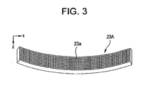
- Fig. 3 is a configurational diagram showing the X-ray detection module 23A corresponding to the column A, of the eight X-ray detection modules 23A, 23B, 23C, 23D, 23E, 23F, 23G and 23H constituting the X-ray detector array 23 employed in the present embodiment.
- the X-ray detection module 23A includes the X-ray detection elements 23a laid out in array form in the channel direction x and the body axial direction z.
- a plurality of the X-ray detection elements 23a arranged on a two-dimensional basis form an X-ray incident plane bent in the form of a cylindrical concave surface as a whole.
- 1000 X-ray detection elements 23a are arranged in the channel direction x, and, for example, eight X-ray detection elements 23a are arranged in the subject's body axial direction z.
- the X-ray detection modules 23B, 23C, 23D, 23E, 23F, 23G and 23H corresponding to the columns B to H are also similar to the X-ray detection module 23A corresponding to the column A shown in Fig. 3 . Therefore, the X-ray detector array 23 having the eight X-ray detection modules 23A, 23B, 23C, 23D, 23E, 23F, 23G and 23H is capable of generating detection data corresponding to 32 in total where, for example, four detection data are generated per module.
- Each of the X-ray detection elements 23a consists of a combination of a scintillator and a photo diode, for example.
- the X-ray detection element 23a is not limited to it but may be a semiconductor X-ray detection element using Cadmium Telluride (CdTe) or the like or an ionization chamber type X-ray detection element 23a using xenon (Xe) gas.
- first detection data are generated from X-ray's row data detected by X-ray detection elements 23a adjacent to the boundaries among the plurality of X-ray detection modules 23A, 23B, 23C, 23D, 23E, 23F, 23G and 23H.
- Second detection data are generated from X-ray's row data detected by X-ray detection elements 23a lying around the X-ray detection elements 23a by which the row data corresponding to the first detection data have been obtained.
- first detection data is obtained from one X-ray detection element 23a located in a position closest to the boundary between the X-ray detection modules 23A and 23B corresponding to A and B.
- second detection data is obtained using three X-ray detection elements 23a close to the X-ray detection element 23a for obtaining the first detection data as viewed in the body axial direction. Since breaks or cut lines exist between the adjacent X-ray detection elements 23a at the boundaries of the plurality of X-ray detection modules 23A, 23B, 23C, 23D, 23E, 23F, 23G and 23H as viewed in the body axial direction z, and the X-ray detection elements 23a lying in the neighborhood of the boundaries among the X-ray detection modules 23A, 23B, 23C, 23D, 23E, 23F, 23G and 23H as viewed in the body axial direction z and the X-ray detection elements 23a lying therearound are different from one another in the number of the X-ray detection elements 23a respectively adjacent thereto, profiles of the generated amounts of crosstalk in the body axial direction become discontinuous. Therefore, the first detection data contains the generated amount of crosstalk different from the second detection data.
- a first radiation detection element according to the present invention is constituted of each of the X-ray detection elements 23a which are adjacent to the boundaries of the plurality of X-ray detection modules 23A, 23B, 23C, 23D, 23E, 23F, 23G and 23H of the X-ray detector array 23 and detect the X-ray defined as the first detection data.
- a second radiation detection element according to the present invention is comprised of each of the X-ray detection elements 23a lying around the X-ray detection elements 23a that detect the X-ray to be assumed as the first detection data.
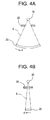
- Figs. 4 and 5 are respectively diagrams showing the interrelationship among the X-ray tube 20, the collimator 22 and the X-ray detector array 23.
- Fig. 4(a) is a diagram showing a state in which the subject's body axial direction z is seen from the side as defined as a visual line
- Fig. 4(b) is a diagram showing a state in which the channel direction x is seen from the side as defined as a visual line
- Fig. 5 is a diagram showing the manner in which a subject 6 to be imaged is shot or imaged in a state in which the channel direction x is seen from the side as defined as a visual line in a manner similar to Fig. 4(b) .
- an X-ray 5 radiated from the X-ray tube 20 is formed so as to assume a cone-shaped X-ray 5 having predetermined cone angles by the collimator 22, which in tum is applied to a predetermined area of the X-ray detector array 23.
- the subject 6 placed on the imaging table 4 is carried in the X-ray irradiation space 29, where the periphery of the subject 6 is scanned with the body axial direction of the subject 6 as the axis and the X-ray 5 is applied to an imaging area of the subject 6 through the X-ray tube 5.
- the X-ray 5 radiated from the X-ray tube 20 passes through the subject 6 via the collimator 22 and is detected by the X-ray detector array 23.
- the data acquisition section 24 collects row data detected by the individual X-ray detection elements 23a in the X-ray detector array 23 and outputs it to the operating console 3, As shown in Fig. 2 , the data acquisition section 24 has, for example, a selection/addition switching circuit (MUX, ADD) 241 and an analog-digital converter (ADC) 242.
- the selection/addition switching circuit 241 selects the row data detected by the X-ray detection elements 23a of the X-ray detector array 23 in accordance with a control signal CTL303 transmitted from a central processing unit 30 of the operating console 3 or changes their combinations and adds them together, and outputs the result thereof to the analog-digital converter 242.
- the analog-digital converter 242 converts the row data selected or added together in arbitrary combinations in the selection/addition switching circuit 241 from an analog signal to a digital signal, followed by being outputted to the central processing unit 30 of the operating console 3.
- the X-ray controller 25 outputs a control signal CTL251 to the X-ray tube 20 in accordance with a control signal CTL301 sent from the central processing unit 30 of the operating console 3 to thereby control X-ray radiation. Also the X-ray controller 25 outputs a control signal CTL252 to the X-ray tube moving section 221 in accordance with the control signal CT301 supplied from the central processing unit 30 of the operating console 3 to move the center of radiation of the X-ray tube 20 by a distance corresponding to instructions in the subject's body axial direction Z.
- the collimator controller 26 outputs a control signal CTL261 to the collimator 22 in accordance with a control signal CTL302 supplied from the central processing unit 30 of the operating console 3 to adjust the degree of opening of the aperture 221 of the collimator 22 and allow the X-ray 5 radiated from the X-ray tube 20 to be formed, thereby irradiating a desired area of the X-ray detector array 23 with the X-ray 5.
- the rotating section 27 is rotated in a predetermined direction based on a control signal CTL28 sent from the rotation controller 28.
- the rotation section 27 is equipped with the X-ray tube 20, the X-ray tube moving section 21, the collimator 22, the X-ray detector array 23, the data acquisition section 24, the X-ray controller 25 and the collimator controller 26. These components vary in position relation with respect to the subject 6 carried in the X-ray irradiation space 29 with the rotation of the rotating section 27.
- the X-rays are radiated from a plurality of view directions with the body axial direction of the subject 6 as the axis and the X-ray 5 transmitted through the subject 6 is detected.
- the rotation controller 28 outputs the control signal CTL28 to the rotating section 27 in accordance with a control signal CTL304 outputted from the central processing unit 30 of the operating console 3 to thereby rotate the rotating section 27 by a desired number of revolutions in a predetermined direction.
- the operating console 3 has as main components the central processing unit 30, an input device 31, a display device 32 and a memory device 33.
- the central processing unit 30 includes a fitting processing means and a tomographic image generating means according to the present invention.
- the display device 32 constitutes a display means according to the present invention.
- the central processing unit 30 comprises a microcomputer or the like, for example and has programs corresponding to various functions.
- the central processing unit 30 outputs a control signal CTL30b to the imaging table 4 in accordance with instructions inputted from the input device 31 in order to cause the imaging table 4 with the subject 6 placed thereon to be carried in the X-ray irradiation space 29 of the scanning gantry 2 or be carried out therefrom.
- the central processing unit 30 outputs the control signal CTL304 to the rotating controller 28 of the scanning gantry 2 in response to multi-slice scan start instructions inputted from the input device 31 to thereby rotate the rotating section 27 of the scanning gantry 2 in a predetermined direction at the number of revolutions corresponding to instructions.
- the central processing unit 30 outputs the control signal CTL301 to the X-ray controller 25 to cause the X-ray tube 20 of the scanning gantry 2 to radiate the X-ray 5.
- the central processing unit 30 outputs the control signal CTL301 to the X-ray controller 25 in response to information about an imaging area of the subject 6, which is inputted from the input device 31, to thereby move the center of radiation of the X-ray tube 20 by a distance corresponding to instructions in the body axial direction z.
- the central processing unit 30 outputs the control signal CTL302 for controlling the collimator 22 so as to provide the predetermined degree of opening of the aperture to the collimator controller 26 in order to radiate the X-ray 5 into a predetermined range.
- the central processing unit 30 outputs the control signal CTL303 to the selection/addition switching circuit 241 of the data acquisition section 24 so as select row data obtained by the X-ray detection elements 23a in the X-ray detector array 23 or change their combinations and add the same together, in accordance with information about the imaging area of the subject 6, which is inputted from the input device 31. Also the central processing unit 30 effects pre-treatment such as sensitivity correction on the row data collected by the data acquisition section 24 to thereby generate detection data.
- the central processing unit 30 has a program that functions as a fitting processing means.
- the fitting processing means performs fitting processing on the detection data so as to cause first detection data generated by the X-ray detection elements 23a adjacent to the boundaries of the plurality of X-ray detection modules to be adapted to waveform data based on second detection data generated by the X-ray detection elements 23a lying around the X-ray detection elements 23a having generated the first detection data.
- the fitting processing means performs fitting processing through the use of the first detection data and the second detection data.
- the fitting processing means give weighting factors to the first detection data and the second detection data so that they are adapted to waveform data expressed in a polynomial equation derived from a least squares error reference, using the first detection data and the second detection data to normalize the first detection data, thereby performing fitting processing on the detection data.
- the details of the fitting processing using the first detection data and the second detection data will be described later.
- the central processing unit 30 has a program that functions as a tomographic image generating means and performs an image reconstruction, based on the detection data from a plurality of view directions to generate plural tomographic images.
- the first detection data and second detection data subjected to the fitting processing are used as the detection data.
- a filtered back projection method is used in the image reconstruction of the central processing unit 30.
- the central processing unit 30 causes the display device 32 to display a reconstructed image thereon.
- the input device 31 is provided to input information such as imaging conditions to the central processing unit 30 and is constituted of, for example, a keyboard or a mouse. Incidentally, the input device 31 may be connected to the scanning gantry 2 or the imaging table 4.
- the display device 32 displays a reconstructed and produced tomographic image and other various information thereon based on a command issued from the central processing unit 30.
- the memory device 33 stores various data, reconstructed images and programs therein. The stored data is accessed by the central processing unit 30 as needed.
- Fig. 6 is a diagram showing detection data generated based on an X-ray detected by sections of the two X-ray detection modules 23A and 23B, of the X-ray detector array 23 employed in the present embodiment, corresponding to A and B, which are arranged in parallel adjacent to each other in the body axial direction z, wherein Fig. 6(a) shows the data prior to the fitting processing, and Fig. 6(b) illustrates the data subsequent to the fitting processing.
- Fig. 6 shows sections in which the two X-ray detection modules 23A and 23B respectively have eight X-ray detection elements 23a arranged in the channel direction x and four X-ray detection elements 23a arranged in the body axial direction z.
- spots surrounded by rectangles in Fig. 6(a) show first detection data A41 through A48 and B11 through B18 obtained by the X-ray detected by X-ray detection elements 23a adjacent to a boundary K between the two X-ray detection modules 23A and 23B.
- Fig. 7 is a plotted diagram of detection data obtained by the X-ray detection elements 23a arranged in the body axial direction in the present embodiment, wherein Fig. 7(a) shows the detection data prior to the fitting processing process, and Fig. 7(b) shows the detection data subsequent to the fitting processing process.
- the horizontal axis indicates the position of each X-ray detection element 23a that obtains the detection data
- the vertical axis indicates data values of detection data generated based on the intensities of detected X-rays.
- an operator first inputs information about an imaging area of a subject 6 to be imaged to the central processing unit 30 via the input device 31 ahead of the scanning of an X-ray 5. Then the central processing unit 30 outputs a control signal CTL30b for carrying the imaging table 4 with the subject 6 placed thereon in the X-ray irradiation space 29 of the scanning gantry 2 or carrying out it therefrom to the imaging table 4 on the basis of the information inputted from the input device 31 and positions the imaging area of the subject 6 so that the imaging area thereof is placed in a desired position of the X-ray irradiation space 29 of the scanning gantry 2.
- the central processing unit 30 outputs a control signal CTL301 to the X-ray controller 25 and causes the X-ray controller 25 to output a control signal CTL251 to the X-ray tube 20, thereby executing radiation of X-ray 5 from the X-ray tube 20. Further, the central processing unit 30 outputs a control signal CTL302 to the collimator controller 26 and allows the collimator controller 26 to supply a control signal CTL261 for controlling the degree of opening of the aperture 221 of the collimator 22 to the collimator 22.
- An X-ray transmitted through the imaging area of the subject 6 is detected by the X-ray detector array 23 which includes the X-ray detection modules in which the X-ray detection elements 23a are disposed in array form, and wherein the X-ray detection modules are disposed adjacent to one another. Then the X-ray 5 detected by the X-ray detector array 23 is subjected to pre-treatment such as sensitivity correction to thereby produce detection data.
- waveform data based on the detection data A11, A21, A31, A41,B11, B21, B31 and B41 having the first detection data and second detection data are discontinuous at a portion between the first detection data A41 and B11.
- This cause results from the fact that since the portions equivalent to the first detection data A41 and B11 are obtained from X-rays detected by X-ray detection elements 23a adjacent to boundaries K between a plurality of X-ray detection modules 23A and 238, the portions are different from the generated amount of crosstalk contained in the second detection data A11, A21, A31, B21, B31 and B41.
- detection data are subjected to fitting processing in such a manner that, of the detection data generated by an X-ray detected by the X-ray detector array 23, first detection data generated by an X-ray detected by X-ray detection elements 23a adjacent to the boundaries between the plurality of X-ray detection modules 23A and 23B are adapted to waveform data based on second detection data generated by radiation detected by X-ray detection elements 23a lying around the X-ray detection elements 23a that obtain the first detection data, in a fitting processing process employed in the X-ray tomography method.
- the fitting processing means of the X-ray CT apparatus according to the present invention is provided in the central processing unit 30.
- the fitting processing means calculates dummy data corresponding to first detection data according to fitting processing using only second detection data and substitutes the dummy data with the first detection data.
- Fig. 6 is a diagram showing detection data generated by an X-ray detected by portions or sections of two X-ray detection modules 23A and 23B corresponding to A and B, of an X-ray detector array 23 according to the present embodiment, which modules are arranged in parallel adjacent to each other as viewed in a body axis direction z, wherein Fig. 6(a) shows the data prior to fitting processing, and Fig. 6(b) shows the data subsequent to the fitting processing. Fig. 6 shows sections in which the two X-ray detection modules 23A and 23B respectively have eight X-ray detection elements 23a arranged in a channel direction x and four X-ray detection elements 23a arranged in the body axial direction z.
- spots surrounded by rectangles in Fig. 6(a) show first detection data A41 through A48 and B11 through B18 obtained by the X-ray detected by the X-ray detection elements 23a adjacent to a boundary K between the two X-ray detection modules 23A and 23B.
- a fitting processing process calculates dummy data corresponding to first detection data according to fitting processing using only second detection data and substitutes the dummy data with the first detection data.
- second detection data A11, A21, A31, B21, B31 and B41 are subjected to filtering processing using a low-pass filter to derive waveform data based on the second detection data A11, A21, A31, B21, B31 and B41.
- dummy data A"41 and B"11 corresponding to the first detection data A41 and B11 are calculated using the waveform data, and then substituted with the first detection data A41 and B11 to thereby execute fitting processing.
- the present embodiment is capable of preventing a reduction in the contrast of a tomographic image and the occurrence of artifacts, improving the quality of a tomographic image generated by reconstruction, and providing high-speed imaging.
- the central processing unit 30 performs an image reconstruction on the basis of the detection data subjected to the fitting processing to generate tomographic image data.
- the central processing unit 30 causes the display device 32 to display the tomographic image generated in the tomographic image generating process.
- an X-ray is applied to an imaging area of a subject to be imaged.
- the X-ray transmitted through the imaging area of the subject is detected by X-ray detection elements disposed in array form in a plurality of X-ray detection modules arranged adjacent to one another in a subject's body axial direction.
- first detection data generated by the X-ray detected by X-ray detection elements adjacent to boundaries among the plurality of X-ray detection modules are subjected to fitting processing so as to be adapted to waveform data based on second detection data generated by the X-ray detected by X-ray detection elements lying therearound as viewed in the subject's body axial direction.
- the first detection data detected by the X-ray detection elements lying in the neighborhood of the boundaries among the plural X-ray detection modules as viewed in the body axial direction are corrected so as to contain the generated amount of crosstalk where the data are not affected by the boundaries among the X-ray detection modules as viewed in the body axial direction. That is, the first detection data are corrected such that profiles of the generated amount of crosstalk as viewed in the body axial direction become continuous.
- the first detection data are corrected based on detection data obtained upon imaging of the imaging area of the subject without using the predetermined generated amount of crosstalk. Therefore, the present embodiment is capable of providing high-accuracy correction, preventing a reduction in the contrast of a tomographic image and the occurrence of artifacts and improving the quality of a tomographic image generated by reconstruction.
- the present invention is not limited to the above-described embodiments. Various modifications can be adopted.
- detection data lying in the neighborhood of boundaries among a plurality of X-ray detection modules as viewed in a body axial direction are subjected to fitting processing in the present embodiment, for example, detection data in the neighborhood of boundaries among the plurality of X-ray detection modules as viewed in a channel direction may be applied.
- both the first detection data and the second detection data may use an arbitrary number of detection data, based on waveform data corresponding to the whole detection data.
Landscapes
- Health & Medical Sciences (AREA)
- Life Sciences & Earth Sciences (AREA)
- Engineering & Computer Science (AREA)
- Medical Informatics (AREA)
- Pathology (AREA)
- Physics & Mathematics (AREA)
- General Health & Medical Sciences (AREA)
- Nuclear Medicine, Radiotherapy & Molecular Imaging (AREA)
- Radiology & Medical Imaging (AREA)
- Pulmonology (AREA)
- Theoretical Computer Science (AREA)
- Heart & Thoracic Surgery (AREA)
- Veterinary Medicine (AREA)
- Biomedical Technology (AREA)
- High Energy & Nuclear Physics (AREA)
- Molecular Biology (AREA)
- Surgery (AREA)
- Animal Behavior & Ethology (AREA)
- Biophysics (AREA)
- Public Health (AREA)
- Optics & Photonics (AREA)
- Chemical & Material Sciences (AREA)
- Analytical Chemistry (AREA)
- Biochemistry (AREA)
- General Physics & Mathematics (AREA)
- Immunology (AREA)
- Apparatus For Radiation Diagnosis (AREA)
- Measurement Of Radiation (AREA)
- Nuclear Medicine (AREA)
- Transforming Light Signals Into Electric Signals (AREA)
Claims (6)
- Strahlentomographievorrichtung umfassend:eine Bestrahlungseinrichtung (20) zur Bestrahlung eines mittels Strahlen abzubildenden Bildgebungsbereiches einer Person (6);eine Strahlendetektionseinrichtung (23) mit erstem und zweitem Strahlendetektionsmodul (23A, 23B), in welchen die durch den Bildgebungsbereich der Person (6) transmittierte Strahlen detektierende Strahlendetektionselemente (23a) reihenförmig angeordnet sind, wobei das erste und das zweite Strahlendetektionsmodul (23A, 23B) aneinander angrenzend angeordnet sind; undeine Fittingverarbeitungseinrichtung zur Durchführung einer Fittungsverarbeitung an den Detektionsdaten in einer derartigen Weise, dass aus den durch die Strahlen erzeugten und durch die Strahlendetektionseinrichtung (23) detektierten Detektionsdaten durch die Strahlen erzeugte und durch erste Strahlendetektionselemente, welche den an eine Grenze zwischen dem ersten und dem zweiten Strahlendetektionsmodul (23A, 23B) angrenzenden Strahlendetektionselementen entsprechen, detektierte erste Detektionsdaten (A41-A48, B11-B18) zu Wellenformatdaten verabeitet werden, welche auf durch die Strahlen erzeugte und durch zweite Strahlendetektionselemente, welche den um die ersten Strahlenelemente liegenden Strahlendetektionselementen entsprechen, detektierte zweite Detektionsdaten (A11-A18, A21-A28, A31-A38, B21-B28, B31-B38, B41-B48,) gestützt sind;dadurch gekennzeichnet, dass die Fittingverarbeitungseinrichtung den ersten Detektionsdaten entsprechende Dummy-Daten gemäß einer Fittingverarbeitung unter ausschließlicher Verwendung der zweiten Detektionsdaten berechnet und die Dummy-Daten mit den ersten Detektionsdaten ersetzt.
- Strahlentomographievorrichtung nach Anspruch 1, wobei die Fittingverarbeitungseinrichtung den ersten Detektionsdaten entsprechende erste Dummy-Daten durch das erste bzw. zweite Strahlendetektionsmodul (23A, 23B) gemäß der Fittingverarbeitung unter Verwendung der zweiten Detektionsdaten berechnet, den Differenzen zwischen den ersten Dummy-Daten und den ersten Detektionsdaten entsprechende Daten durch das erste bzw. zweite Strahlendetektionsmodul (23A, 23B) berechnet, die Mittelwertdaten der Differenzdaten durch das erste bzw. zweite Strahlendetektionsmodul (23A, 23B) berechnet, den Differenzen zwischen den ersten Daten und den Differenzmittelwertdaten entsprechende zweite Dummy-Daten durch das erste bzw. zweite Strahlendetektionsmodul (23A, 23B) berechnet und die dem ersten bzw. zweiten Strahlendetektionsmodul (23A, 23B) entsprechenden ersten Detektionsdaten mit den zweiten Dummy-Daten ersetzt.
- Strahlentomographievorrichtung nach Anspruch 1 oder 2, weiter umfassend eine Tomographiebilderzeugungseinrichtung zu Erzeugung von Tomographiebilddaten des Bildgebungsbereiches der Person, welche auf die der Fittingverabeitung unterworfenen Daten gestützt sind.
- Strahlentomographievorrichtung nach Anspruch 3, weiter umfassend eine Anzeigeeinrichtung (32) zur Anzeige eines Tomographiebildes, gestützt auf die durch die Tomographiebilderzeugungseinrichtung erzeugten Tomographiebilddaten.
- Strahlentomographievorrichtung nach einem der Ansprüche 1 bis 4, wobei die Bestrahlungseinrichtung (20) Röntgenstrahlen als Strahlen anwendet.
- Strahlentomographieverfahren unter Verwendung einer Strahlentomographievorrichtung mit
einer Bestrahlungseinrichtung (20) zur Bestrahlung eines mittels Strahlen abzubildenden Bildgebungsbereiches einer Person (6); und
einer Strahlendetektionseinrichtung (23) mit erstem und zweitem Strahlendetektionsmodul (23A, 23B), in welchen die durch den Bildgebungsbereich der Person (6) transmittierte Strahlen detektierende Strahlendetektionselemente (23a) reihenförmig angeordnet sind, wobei das erste und das zweite Strahlendetektionsmodul (23A, 23B) aneinander angrenzend angeordnet sind, umfassend:
einen Fittingverarbeitungsablauf zur Durchführung einer Fittungsverarbeitung an den Detektionsdaten in einer derartigen Weise, dass aus den durch die Strahlen erzeugten und durch die Strahlendetektionseinrichtung (23) detektierten Detektionsdaten durch die Strahlen erzeugte und durch erste Strahlendetektionselemente, welche den an eine Grenze zwischen dem ersten und dem zweiten Strahlendetektionsmodul (23A, 23B) angrenzenden Strahlendetektionselementen entsprechen, detektierte erste Detektionsdaten (A41-A48, B11-B18) zu Wellenformatdaten verabeitet werden, welche auf durch die Strahlen erzeugte und durch zweite Strahlendetektionselemente, welche den um die ersten Strahlenelemente liegenden Strahlendetektionselementen entsprechen, detektierte zweite Detektionsdaten (A11-A18, A21-A28, A31-A38, B21-B28, B31-B38, B41-B48,) gestützt sind;
dadurch gekennzeichnet, dass der Fittingverarbeitungsablauf den ersten Detektionsdaten entsprechende Dummy-Daten gemäß einer Fittingverarbeitung unter ausschließlicher Verwendung der zweiten Detektionsdaten berechnet und die Dummy-Daten mit den ersten Detektionsdaten ersetzt.
Applications Claiming Priority (2)
| Application Number | Priority Date | Filing Date | Title |
|---|---|---|---|
| JP2003315505A JP4041040B2 (ja) | 2003-09-08 | 2003-09-08 | 放射線断層撮影装置 |
| JP2003315505 | 2003-09-08 |
Publications (2)
| Publication Number | Publication Date |
|---|---|
| EP1512376A1 EP1512376A1 (de) | 2005-03-09 |
| EP1512376B1 true EP1512376B1 (de) | 2009-11-11 |
Family
ID=34131932
Family Applications (1)
| Application Number | Title | Priority Date | Filing Date |
|---|---|---|---|
| EP04255382A Expired - Lifetime EP1512376B1 (de) | 2003-09-08 | 2004-09-03 | Strahlentomographievorrichtung und Strahlentomographieverfahren |
Country Status (6)
| Country | Link |
|---|---|
| US (1) | US7327824B2 (de) |
| EP (1) | EP1512376B1 (de) |
| JP (1) | JP4041040B2 (de) |
| KR (1) | KR20050025914A (de) |
| CN (1) | CN100346747C (de) |
| DE (1) | DE602004024010D1 (de) |
Families Citing this family (16)
| Publication number | Priority date | Publication date | Assignee | Title |
|---|---|---|---|---|
| JP5011482B2 (ja) * | 2005-07-19 | 2012-08-29 | ジーイー・メディカル・システムズ・グローバル・テクノロジー・カンパニー・エルエルシー | X線ct装置 |
| JP5010859B2 (ja) * | 2005-12-21 | 2012-08-29 | ジーイー・メディカル・システムズ・グローバル・テクノロジー・カンパニー・エルエルシー | 画像生成装置 |
| ES2299352B1 (es) * | 2006-06-09 | 2009-02-16 | Centro De Investigaciones Energeticas, Medioambientales Y Tecnologias (C.I.E.M.A.T). | Detector o maniqui polimorfico para la deteccion de particulas energeticas compuesto de piezas individuales. |
| KR101040488B1 (ko) * | 2006-08-08 | 2011-06-09 | 가부시키가이샤 시마즈세이사쿠쇼 | 방사선 촬상 장치 |
| WO2008093275A2 (en) | 2007-02-01 | 2008-08-07 | Koninklijke Philips Electronics N.V. | Event sharing restoration for photon counting detectors |
| US7512210B2 (en) * | 2007-03-27 | 2009-03-31 | General Electric Company | Hybrid energy discriminating charge integrating CT detector |
| JP5648898B2 (ja) * | 2010-05-28 | 2015-01-07 | 東芝Itコントロールシステム株式会社 | Ct装置 |
| WO2013191001A1 (ja) * | 2012-06-20 | 2013-12-27 | 株式会社日立メディコ | X線ct装置 |
| CN104665859B (zh) * | 2013-11-29 | 2017-12-15 | 通用电气公司 | 成像系统 |
| CN110300950B (zh) | 2017-02-06 | 2023-06-16 | 平蛙实验室股份公司 | 触摸感测系统中的光学耦合 |
| JP6717784B2 (ja) * | 2017-06-30 | 2020-07-08 | アンリツインフィビス株式会社 | 物品検査装置およびその校正方法 |
| CN111052058B (zh) | 2017-09-01 | 2023-10-20 | 平蛙实验室股份公司 | 改进的光学部件 |
| US11567610B2 (en) | 2018-03-05 | 2023-01-31 | Flatfrog Laboratories Ab | Detection line broadening |
| CN112889016A (zh) | 2018-10-20 | 2021-06-01 | 平蛙实验室股份公司 | 用于触摸敏感装置的框架及其工具 |
| EP4066089B1 (de) | 2019-11-25 | 2024-09-25 | FlatFrog Laboratories AB | Ein berührungsempfindliches gerät |
| WO2021158164A1 (en) | 2020-02-08 | 2021-08-12 | Flatfrog Laboratories Ab | Touch apparatus with low latency interactions |
Family Cites Families (14)
| Publication number | Priority date | Publication date | Assignee | Title |
|---|---|---|---|---|
| US4670840A (en) | 1983-03-09 | 1987-06-02 | Elscint, Inc. | Ring artifact correction for computerized tomography |
| US4897788A (en) | 1988-04-18 | 1990-01-30 | General Electric Company | Image correction for computed tomography to remove crosstalk artifacts |
| US5099505A (en) | 1990-07-02 | 1992-03-24 | Varian Associates | Method for increasing the accuracy of a radiation therapy apparatus |
| JPH0966052A (ja) | 1995-08-31 | 1997-03-11 | Shimadzu Corp | X線ct装置 |
| JPH09234197A (ja) | 1996-02-29 | 1997-09-09 | Shimadzu Corp | X線映像装置 |
| JP3828967B2 (ja) | 1996-10-30 | 2006-10-04 | 株式会社東芝 | X線ctスキャナ |
| US5764720A (en) * | 1996-12-26 | 1998-06-09 | General Electric Company | Methods and apparatus for simplified pre-processing of data in a computed tomography system |
| US6067342A (en) | 1997-10-30 | 2000-05-23 | Analogic Corporation | Digital filmless X-ray projection imaging system and method |
| JP4194128B2 (ja) * | 1998-03-13 | 2008-12-10 | 株式会社東芝 | X線ct装置 |
| DE19956585A1 (de) | 1999-11-25 | 2001-05-31 | Philips Corp Intellectual Pty | Computertomographie-Verfahren |
| EP1107260B1 (de) | 1999-11-30 | 2008-10-15 | Philips Intellectual Property & Standards GmbH | Gitter zur Absorption von Röntgenstrahlen |
| US6859514B2 (en) * | 2003-03-14 | 2005-02-22 | Ge Medical Systems Global Technology Company Llc | CT detector array with uniform cross-talk |
| DE102005032275B3 (de) * | 2005-07-11 | 2006-10-12 | Siemens Ag | Verfahren zur Korrektur von Stoßzonenartefakten bei einem Röntgendetektor und Röntgendetektor |
| US7456409B2 (en) * | 2005-07-28 | 2008-11-25 | Carestream Health, Inc. | Low noise image data capture for digital radiography |
-
2003
- 2003-09-08 JP JP2003315505A patent/JP4041040B2/ja not_active Expired - Fee Related
-
2004
- 2004-08-23 US US10/924,097 patent/US7327824B2/en not_active Expired - Fee Related
- 2004-09-03 DE DE602004024010T patent/DE602004024010D1/de not_active Expired - Lifetime
- 2004-09-03 EP EP04255382A patent/EP1512376B1/de not_active Expired - Lifetime
- 2004-09-07 KR KR1020040071134A patent/KR20050025914A/ko not_active Withdrawn
- 2004-09-08 CN CNB2004100791095A patent/CN100346747C/zh not_active Expired - Fee Related
Also Published As
| Publication number | Publication date |
|---|---|
| CN1593341A (zh) | 2005-03-16 |
| JP2005080839A (ja) | 2005-03-31 |
| KR20050025914A (ko) | 2005-03-14 |
| CN100346747C (zh) | 2007-11-07 |
| EP1512376A1 (de) | 2005-03-09 |
| DE602004024010D1 (de) | 2009-12-24 |
| JP4041040B2 (ja) | 2008-01-30 |
| US7327824B2 (en) | 2008-02-05 |
| US20050053191A1 (en) | 2005-03-10 |
Similar Documents
| Publication | Publication Date | Title |
|---|---|---|
| EP1512376B1 (de) | Strahlentomographievorrichtung und Strahlentomographieverfahren | |
| US7409034B2 (en) | Radiation tomography apparatus | |
| JP2825450B2 (ja) | Ctスキャナ | |
| JP3942142B2 (ja) | 放射線断層撮影装置およびその方法 | |
| US7382858B2 (en) | Radiation imaging apparatus | |
| US6134292A (en) | Methods and apparatus for reducing z-axis non-uniformity artifacts | |
| JP2004180715A (ja) | X線コンピュータ断層撮影装置 | |
| JPH08299322A (ja) | Ct装置 | |
| WO2003043499A1 (en) | X-ray ct device, and method for preparing tomographic image thereof | |
| CN100553563C (zh) | X射线ct装置 | |
| JP4194128B2 (ja) | X線ct装置 | |
| JP3774518B2 (ja) | X線ctスキャナ | |
| JP5022690B2 (ja) | 放射線撮影装置 | |
| KR101726485B1 (ko) | 컴퓨터 단층 촬영 시스템의 작동 방법 및 컴퓨터 단층 촬영 시스템 | |
| JP4939702B2 (ja) | X線ct装置 | |
| JP4245204B2 (ja) | X線ct装置 | |
| JP4381099B2 (ja) | 放射線断層撮影装置 | |
| JP4551612B2 (ja) | コンピュータ断層撮影装置 | |
| KR100654589B1 (ko) | 방사선단층촬영방법및장치 | |
| JP2006034963A (ja) | X線検出器およびコンピュータ断層撮影装置 | |
| JPS6362215B2 (de) | ||
| JP4430987B2 (ja) | 放射線断層撮影装置およびその断層撮影方法、補正データ算出方法 | |
| JP2001212132A (ja) | 検査方法および装置、放射線断層撮影装置並びに記録媒体 | |
| JP2006068338A (ja) | 放射線撮影装置 | |
| JP2000060840A (ja) | レファレンス信号生成方法および装置並びに放射線断層撮影装置 |
Legal Events
| Date | Code | Title | Description |
|---|---|---|---|
| PUAI | Public reference made under article 153(3) epc to a published international application that has entered the european phase |
Free format text: ORIGINAL CODE: 0009012 |
|
| AK | Designated contracting states |
Kind code of ref document: A1 Designated state(s): AT BE BG CH CY CZ DE DK EE ES FI FR GB GR HU IE IT LI LU MC NL PL PT RO SE SI SK TR |
|
| AX | Request for extension of the european patent |
Extension state: AL HR LT LV MK |
|
| 17P | Request for examination filed |
Effective date: 20050909 |
|
| AKX | Designation fees paid |
Designated state(s): DE FR GB |
|
| 17Q | First examination report despatched |
Effective date: 20061005 |
|
| GRAP | Despatch of communication of intention to grant a patent |
Free format text: ORIGINAL CODE: EPIDOSNIGR1 |
|
| GRAS | Grant fee paid |
Free format text: ORIGINAL CODE: EPIDOSNIGR3 |
|
| GRAA | (expected) grant |
Free format text: ORIGINAL CODE: 0009210 |
|
| AK | Designated contracting states |
Kind code of ref document: B1 Designated state(s): DE FR GB |
|
| REG | Reference to a national code |
Ref country code: GB Ref legal event code: FG4D |
|
| REF | Corresponds to: |
Ref document number: 602004024010 Country of ref document: DE Date of ref document: 20091224 Kind code of ref document: P |
|
| PLBE | No opposition filed within time limit |
Free format text: ORIGINAL CODE: 0009261 |
|
| STAA | Information on the status of an ep patent application or granted ep patent |
Free format text: STATUS: NO OPPOSITION FILED WITHIN TIME LIMIT |
|
| 26N | No opposition filed |
Effective date: 20100812 |
|
| GBPC | Gb: european patent ceased through non-payment of renewal fee |
Effective date: 20100903 |
|
| REG | Reference to a national code |
Ref country code: FR Ref legal event code: ST Effective date: 20110531 |
|
| PG25 | Lapsed in a contracting state [announced via postgrant information from national office to epo] |
Ref country code: FR Free format text: LAPSE BECAUSE OF NON-PAYMENT OF DUE FEES Effective date: 20100930 |
|
| PG25 | Lapsed in a contracting state [announced via postgrant information from national office to epo] |
Ref country code: GB Free format text: LAPSE BECAUSE OF NON-PAYMENT OF DUE FEES Effective date: 20100903 |
|
| PGFP | Annual fee paid to national office [announced via postgrant information from national office to epo] |
Ref country code: DE Payment date: 20140929 Year of fee payment: 11 |
|
| REG | Reference to a national code |
Ref country code: DE Ref legal event code: R119 Ref document number: 602004024010 Country of ref document: DE |
|
| PG25 | Lapsed in a contracting state [announced via postgrant information from national office to epo] |
Ref country code: DE Free format text: LAPSE BECAUSE OF NON-PAYMENT OF DUE FEES Effective date: 20160401 |