EP1512657A1 - Système d'ascenseur pourvu d'une unité de motorisation sur contrepoids - Google Patents
Système d'ascenseur pourvu d'une unité de motorisation sur contrepoids Download PDFInfo
- Publication number
- EP1512657A1 EP1512657A1 EP04077248A EP04077248A EP1512657A1 EP 1512657 A1 EP1512657 A1 EP 1512657A1 EP 04077248 A EP04077248 A EP 04077248A EP 04077248 A EP04077248 A EP 04077248A EP 1512657 A1 EP1512657 A1 EP 1512657A1
- Authority
- EP
- European Patent Office
- Prior art keywords
- counterweight
- cabin
- elevator system
- sheath
- pulley
- Prior art date
- Legal status (The legal status is an assumption and is not a legal conclusion. Google has not performed a legal analysis and makes no representation as to the accuracy of the status listed.)
- Withdrawn
Links
- 238000006073 displacement reaction Methods 0.000 claims description 13
- 238000012423 maintenance Methods 0.000 description 13
- 238000010586 diagram Methods 0.000 description 8
- 210000000056 organ Anatomy 0.000 description 8
- 230000008439 repair process Effects 0.000 description 4
- 238000012544 monitoring process Methods 0.000 description 1
Images


Classifications
-
- B—PERFORMING OPERATIONS; TRANSPORTING
- B66—HOISTING; LIFTING; HAULING
- B66B—ELEVATORS; ESCALATORS OR MOVING WALKWAYS
- B66B11/00—Main component parts of lifts in, or associated with, buildings or other structures
- B66B11/02—Cages, i.e. cars
- B66B11/0226—Constructional features, e.g. walls assembly, decorative panels, comfort equipment, thermal or sound insulation
- B66B11/0246—Maintenance features
-
- B—PERFORMING OPERATIONS; TRANSPORTING
- B66—HOISTING; LIFTING; HAULING
- B66B—ELEVATORS; ESCALATORS OR MOVING WALKWAYS
- B66B9/00—Kinds or types of lifts in, or associated with, buildings or other structures
- B66B9/04—Kinds or types of lifts in, or associated with, buildings or other structures actuated pneumatically or hydraulically
Definitions
- the present invention relates to an elevator system provided with a unit of motorization on counterweight and planned to facilitate its maintenance.
- a connecting member 50 such as a cable, a cable ply, or a belt
- the pulley 41 being mounted on the counterweight 30, it will also be said that the counterweight 30 is bent. It is the same with the pulley 21 and strands 55 and 56.
- the return pulley 21 being mounted on the cabin 20, it will be said that the cabin 20 is mouflée. In such a system of mittens, the cable length unrolled or wound is double the corresponding displacement of its pulley. So we can note that the cab 20 and the counterweight 30 move of identical lengths and, therefore, at the same speed.
- the mass of the counterweight 30 In the elevator system shown in FIG. 1, to have an equilibrium, the mass of the counterweight 30 must be substantially equal to the mass of the car 20 plus a predetermined load corresponding to half of the nominal load of the car 20. Moreover, when the car 20 is at the top 10, for example at the last bearing 11 n , the counterweight 30 must be in the bottom of the sheath, as shown in FIG. 1 in the dotted situation. Conversely, when the cabin 20 is at the first bearing 11 1 , the counterweight 30 must be at the head of sheath 11 n , as shown in fine lines.
- the maintenance or eventual repair of the motorization unit 40 is for example carried out at the bottom of the pit, but at this point the cabin 20 is at the last landing (situation shown in dotted lines). Conversely, they can be made at the head of the duct, where the electrical control cabinets 70 of the elevator system are generally located, in particular the cabinet for supplying the supply current of said system. But at that moment, the cabin is at the first landing (situation represented in fine lines). It is therefore difficult, if not impossible, to carry out the maintenance or the repair of the elevator system of the state of the art by having simultaneous access to the booth 20 and to the drive unit 40 which is mounted on the counterweight and , a fortiori, the or electrical control cabinets 70. Note that the cabin 20 is carrying many devices necessary for its proper operation and require maintenance as the unit of motorization 40, and in association therewith. For example, the cabin can carry the control cabinet of the elevator system.
- elevator systems in which only one part of the motorisation unit is to be monitored (systematically and relatively common), the other part being mounted in the sheath and not requiring maintenance as frequent as the first part.
- the unit of motorization is a cylinder and its control unit.
- organ to watch the part of the motorization unit which is monitor is called organ to watch.
- the present invention is not limited to an organ monitor who is the motorization unit itself or only a part of the unit of motorization. It includes any type of organ to be monitored which requires a monitoring, and therefore relatively frequent maintenance.
- the object of the present invention is to solve the problem mentioned above of simultaneous access to a set of organs of the elevator system and therefore proposes an elevator system whose general architecture is such that the organ to be monitored which is mounted on the counterweight, for example the drive unit of the system lift can be subject to maintenance or possible repairs from the cabin while having direct access to command in this one.
- an elevator system is of the type which comprises a cabin intended to circulate vertically in a duct so as to serve a plurality of bearings, a counterweight connected to said cabin via pulleys and a connecting member, said counterweight carrying a member to be monitored.
- said link member is arranged so that the displacement of said counterweight in the sheath is lower than that of the cabin and in that the connecting member has a length such as, where the cabin is at a predetermined point of access to inside the sheath, the body to be monitored carried by the counterweight is accessible from the cabin, but also that the cabin and the counterweight can move freely inside the sheath.
- said access point predetermined is a bearing or a bridge provided between two bearings.
- the cabinet or cabinets of control and electrical control of said elevator system are accessible from the elevator car when it is at said predetermined location.
- said cabin has a retractable hatch allowing the access of the organ to be monitored carried by the counterweight from inside said cabin.
- said body monitor is the motorization unit of the elevator.
- said link member is then fixed at a point fixed in the upper part of the sheath, passes into the drive pulley of the unit of motorisation, passes back into at least one pulley of solidarity sheath in its upper part and is fixed at a fixed point of the cabin.
- said motorization unit is a winch and the connecting member passes through a pulley whose clevis is secured to the sheath in its upper part, passes into a pulley whose clevis is attached to the counterweight, passes back into at least one integral pulley of the sheath in its upper part and is fixed at a fixed point of the cabin.
- the counterweight and the cabin are bent so that the ratio of the displacement of the cabin to the displacement of the counterweight is greater than 1.
- the system elevator is of the type where the engine unit of said elevator system is a cylinder.
- said member to be monitored is the control unit of said jack, said control unit being mounted on said counterweight.
- said jack is then mounted so as to that its barrel has one end that is integral with the counterweight and that the free end its rod 92 is integral with a stop in the lower part of the sheath.
- the counterweight also carries a crazy pulley, said connecting member being fixed to a fixed point in the upper part of the sheath, passing in the idle pulley carried by said counterweight, passing back into at least a return pulley secured to the sheath in its upper part and being fixed at a point fixed cabin.
- said counterweight also carries a pulley mad, said connecting member being fixed to a fixed point in the lower part of the sheath, passing through the idler pulley carried by said counterweight and being fixed at a fixed point from the cabin.
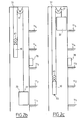
- the elevator system shown in FIG. 2a essentially comprises the same elements as those of the elevator system shown in FIG. 1. These same elements therefore bear the same references.
- the cabin 20 is connected by a connecting member 50 and via pulleys a counterweight 30, which is equipped with a motorization unit 40 provided to drive the cabin 20.
- the body to be monitored merges with the motorization unit 40. It will give by the following an example of realization where this is not the case.
- FIG. 2a One of the essential differences with the elevator system of FIG. 1 lies in the arrangement of the connecting member 50. As can be seen in FIG. 2a, it is fixed at a fixed point 51 of the sheath 10, passes into the drive pulley 41 of the motorization unit 40, passes from new in a return pulley 61, but unlike the system of FIG. 1, is then attached to the cabin 20 at a fixed point 22 thereof.
- the liaison body 50 has strands 52 and 53 which form, with the drive pulley 41, a hauling.
- the pulley 41 being mounted on the counterweight 30, it will also be said that the counterweight 30 is bent.
- the cabin 20 does has no mittens or haul system, so that the movement of the counterweight 30 is lower, in this case by half, than that of the cabin 20.
- the counterweight 30 would have a displacement k times less than the cabin 20. But, for a balance of masses of one and the other, its mass should be k times greater than the mass of the cabin 20 to which a predetermined mass is added corresponding to half the nominal load of the cab 20.
- the second means used by the invention is an adjustment of the length of the connecting member 50 so that when the cabin 20 is at a place predetermined access of the sheath 10, the member which is mounted on the counterweight 30 and which is to be monitored, in this case, in the case of FIG. 2, the motorization unit 40, accessible from the cabin 20, in particular, as is the case in FIG. 2, since inside the cabin 20, for example via a retractable access hatch 23.
- the counterweight 30 is substantially at the same height as the cabin 20.
- a predetermined access location is defined as an access point determined by the designer of the elevator system, an access location that allows more access to the interior of the sheath 10.
- system maintenance elevator having access to the motorization unit 40, to the counterweight 30 and to all the devices that are linked to the cabin 20.
- a retractable access hatch is called a hatch which, in operation normal elevator system (out of maintenance), does not allow and even hides access to the sheath 10 from the cabin 20 and which, during maintenance operations, at the contrary, allows access to the sheath 10 and therefore to the organ to be monitored 40 mounted on the counterweight 30. Any suitable system for such a function is conceivable.
- mechanical means may be provided to lock the movement of the cab 20 and the counterweight 30 and thus obtain a secure position.
- the predetermined access location in question is one of the intermediate bearings, in this case the bearing 11 3 .
- control and control cabinet (s) 70 may be advantageous to mount the control and control cabinet (s) 70 at the predetermined access point (on the bearing 11 3 in the exemplary embodiment of Fig. 4).
- control and control cabinet can be also be mounted inside cabin 20.
- Fig. 2b which represents the elevator system of FIG. 2a with the same length of the connecting member 50, that when the cabin 20 is at the bearing 11 1 , the lowest, the counterweight 30 is not at the top of sheath 10.
- FIG. . 2c when the cab 20 is at bearing 11 5 is the highest, the counterweight 30 is not at the bottom of sheath 10. This is mainly due to the fact that movement of the counterweight 30 is n times lower (here two times lower) that of the cabin 20.
- the predetermined access point where the member mounted on the counterweight 30 which is to be monitored, in this case, the drive unit 40, is accessible from the cab 20 can not be any. It is indeed necessary that the cab 20 and the counterweight 30 can move freely, that is to say without encountering obstacles, inside the sheath 10. To highlight this aspect, it is shown in Figs. 3a and 3b, two embodiments with the same sheath 10 as previously for which this is not the case. Indeed, in FIG. 3a, the predetermined access location is at the second level 11 2 . It can be seen that if the cabin 20 rises by three levels, the counterweight 30 can not go down one and a half steps. Symmetrically in FIG. 3b, the predetermined access location is at the penultimate step 11 4 . It can be seen that if the car 20 descends by three bearings, the counterweight 30 can not go up one and a half steps.
- N be the total number of steps to be serviced and r the rank of the landing where the cabin 20 and the counterweight 30 are at the same level, thus allowing access to the body to be monitored mounted on the counterweight to be accessible from the cabin 20.
- the hauling report is called p.
- FIG. 4 there is shown another embodiment according to which the predetermined access point is a gateway 12 arranged for the access effect for maintenance in the elevator shaft 10 at a level between two levels, occurrence between level 11 3 and level 11 4 .
- the electrical control cabinet 70 At the gateway 12 is mounted the electrical control cabinet 70.
- dashed and in fine lines, are shown the respective positions of the cab 20 and the counterweight 30 when the cabin 20 is respectively at the last and the first bearings.
- the bridge 12 is provided so that it is possible to access the interior of the cabin 20 and, from this interior, the organ to be monitored 40 mounted on the counterweight 30.
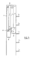
- FIG. 5 there is shown another embodiment where the motorization unit 40 is in fact a winch also mounted on the counterweight 30 and the pulley 41 is an idler pulley which is therefore not driven by the drive unit 40
- the connecting member 50 passes into a pulley 80 whose yoke is secured to the sheath 10 in its upper part, then passes into the idler pulley 41, then rejoins the pulley 61 before reaching attach to the cabin 20.
- three strands 57, 52 and 53 have an end secured to the counterweight 30.
- the ratio p of the displacement of the cab 20 to the displacement of the counterweight 30 is here 3.
- the connecting member 50 is fixed on a fixed point 51 in the upper part of the sheath 10, passes in a crazy pulley 100 whose clevis is integral with the counterweight 30, returns to a return pulley 80 whose yoke is secured to the sheath 10 in its upper part, then passes into the drive pulley 41 of the motor unit 40, then rejoins the pulley 61 in which it passes, passes in a crazy pulley 110 whose yoke is secured to the cabin 20, passes into a pulley 120 whose clevis is secured to the sheath 10 in its upper part then is fixed to the cabin 20 at a fixed point 22.
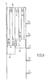
- FIG. 7 there is shown another embodiment where the drive unit 40 is in fact a cylinder 90 whose barrel 91 has one end which is integral with the counterweight 30 and whose free end of the rod 92 is integral with a stop 12 at the bottom of the sheath 10.
- the oil supply of the jack 90 is provided by a hydraulic unit 93 which is mounted on the counterweight 30.
- the connecting member 50 it is fixed to a fixed point 51 in the upper part of the sheath 10 passes into an idler pulley 41 mounted on a yoke 32 integral with the counterweight 30, passes through a pulley 61 in the upper part of the sheath 10 and is fixed on the cabin 20
- the length of the connecting member 50 is such that when the cabin 20 is at a predetermined access point, here the bearing 11 3 , the body to be monitored of the unit of motorization 40, in this case the control unit 93 of the jack 90, for example Its hydraulic power unit is accessible from the cabin 20, particularly as is the case in the drawing, from the inside of the cabin 20, via a hatch in the bottom thereof.
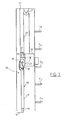
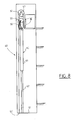
- FIG. 8 there is shown another embodiment of the present invention where the drive unit 40 is also a cylinder 90 whose barrel 91 has one end which is integral with the counterweight 30 and whose free end of the rod 92 is integral with a stop 12 of the sheath 10.
- the control of the cylinder 90 is provided by a control unit 93, for example a hydraulic unit, which is mounted on the counterweight 30.
- a control unit 93 for example a hydraulic unit, which is mounted on the counterweight 30.
- the connecting member 50 it is fixed at a fixed point 51 'in the lower part of the sheath 10, passes into an idler pulley 41 mounted on a yoke 32 integral with the counterweight 30, and is fixed to the cabin 20, for example in the part bass of it.
- the length of the connecting member 50 is such that when the cabin 20 is at a predetermined access point, here the last bearing 11 5 , the body to be monitored of the motorization unit 40, in this case , the hydraulic unit 93, is accessible from the cabin 20, particularly as is the case in the drawing, from inside the cabin 20 via a trap in the bottom thereof.
- the hauling of the counterweight is always higher than that of the cabin so that it has a length of displacement less than the traveling length of the cabin 20.
Landscapes
- Engineering & Computer Science (AREA)
- Structural Engineering (AREA)
- Automation & Control Theory (AREA)
- Civil Engineering (AREA)
- Mechanical Engineering (AREA)
- Lift-Guide Devices, And Elevator Ropes And Cables (AREA)
- Cage And Drive Apparatuses For Elevators (AREA)
Abstract
Description
Claims (13)
- Système d'ascenseur du type comportant une cabine (20) prévue pour circuler verticalement dans une gaine (10) de manière à desservir une pluralité de paliers (111 à 11 n), un contrepoids (30) relié à ladite cabine (20) via des poulies et par un organe de liaison (50), ledit contrepoids (30) portant un organe à surveiller (40), caractérisé en ce que ledit organe de liaison (50) est arrangé de manière à ce que le déplacement dudit contrepoids (30) dans la gaine (10) soit inférieur à celui de la cabine (20) et en ce que l'organe de liaison (50) présente une longueur totale telle que lorsque la cabine (20) se trouve à un endroit prédéterminé d'accès à l'intérieur de la gaine (10), l'organe à surveiller (40) porté par le contrepoids (30) soit accessible depuis la cabine (20), mais telle aussi que la cabine (20) et le contrepoids (30) puissent se déplacer librement à l'intérieur de la gaine (10).
- Système d'ascenseur selon la revendication 1, caractérisé en ce que ledit endroit d'accès prédéterminé est un palier (11).
- Système d'ascenseur selon la revendication 1, caractérisé en ce que ledit endroit d'accès prédéterminé est une passerelle (12) prévue entre deux paliers.
- Système d'ascenseur selon une des revendications précédentes, caractérisé en ce que la ou les armoires de contrôle et de commande électrique (70) dudit système d'ascenseur sont accessibles depuis la cabine d'ascenseur (20) lorsque celle-ci se trouve audit endroit prédéterminé.
- Système d'ascenseur selon une des revendications précédentes, caractérisé en ce que ladite cabine (20) comporte une trappe escamotable (23) permettant l'accès de l'organe à surveiller (40) porté par le contrepoids (30) depuis l'intérieur de ladite cabine (20).
- Système d'ascenseur selon une des revendications précédentes, caractérisé en ce que ledit organe à surveiller (40) est l'unité de motorisation de l'ascenseur.
- Système d'ascenseur selon la revendication 6, caractérisé en ce que ledit organe de liaison (50) est fixé à un point fixe (51) en partie haute de la gaine (10), passe dans la poulie d'entraínement (41) de l'unité de motorisation (40), passe de nouveau dans au moins une poulie de renvoi (61) solidaire de la gaine (10) dans sa partie haute et est fixé en un point fixe (22) de la cabine (20).
- Système d'ascenseur selon la revendication 6, caractérisé en ce que ladite unité de motorisation (40) est un treuil et en ce que l'organe de liaison (50) passe dans une poulie de renvoi (80) dont la chape est solidaire de la gaine (10) dans sa partie haute, passe dans une poulie (41) dont la chape est solidaire du contrepoids (30), passe de nouveau dans au moins une poulie de renvoi (61) solidaire de la gaine (10) dans sa partie haute et est fixé en un point fixe (22) de la cabine (20).
- Système d'ascenseur selon la revendication 6, caractérisé en ce que le contrepoids (30) et la cabine (20) sont mouflés de manière à ce que le rapport du déplacement de la cabine (20) au déplacement du contrepoids (30) est supérieur à 1.
- Système d'ascenseur du type où l'unité de motorisation (40) dudit système d'ascenseur est un vérin (90), système d'ascenseur en outre selon une des revendications 1 à 5, caractérisé en ce que ledit organe à surveiller l'unité de commande (93) dudit vérin (90), ladite unité de commande (93) étant montée sur ledit contrepoids (30).
- Système d'ascenseur selon la revendication 10, caractérisé en ce que ledit vérin (90) est monté de manière que son fût (91) ait une extrémité qui est solidaire du contrepoids (30) et que l'extrémité libre de sa tige 92 soit solidaire d'une butée (12) en partie basse de la gaine (10).
- Système d'ascenseur selon la revendication 11, caractérisé en ce que le contrepoids (30) porte également une poulie folle (41), ledit organe de liaison (50) étant fixé à un point fixe (51) en partie haute de la gaine (10), passant dans la poulie folle (41) portée par ledit contrepoids (30), passant de nouveau dans au moins une poulie de renvoi (61) solidaire de la gaine (10) dans sa partie haute et étant fixé en un point fixe (22) de la cabine (20).
- Système d'ascenseur selon la revendication 11, caractérisé en ce que ledit contrepoids (30) porte également une poulie folle (41), ledit organe de liaison (50) étant fixé à un point fixe (51') dans la partie basse de la gaine (10), passant dans la poulie folle (41) portée par ledit contrepoids (30) et étant fixé en un point fixe (22) de la cabine (20).
Applications Claiming Priority (4)
| Application Number | Priority Date | Filing Date | Title |
|---|---|---|---|
| FR0310176 | 2003-08-26 | ||
| FR0310176A FR2877931A1 (fr) | 2003-08-26 | 2003-08-26 | Systeme d'ascenseur pourvu d'une unite de motorisation sur contrepoids |
| FR0311236 | 2003-09-25 | ||
| FR0311236A FR2877932B1 (fr) | 2003-08-26 | 2003-09-25 | Systeme d'ascenseur pourvu d'une unite de motorisation sur contrepoids |
Publications (1)
| Publication Number | Publication Date |
|---|---|
| EP1512657A1 true EP1512657A1 (fr) | 2005-03-09 |
Family
ID=34137705
Family Applications (1)
| Application Number | Title | Priority Date | Filing Date |
|---|---|---|---|
| EP04077248A Withdrawn EP1512657A1 (fr) | 2003-08-26 | 2004-08-06 | Système d'ascenseur pourvu d'une unité de motorisation sur contrepoids |
Country Status (2)
| Country | Link |
|---|---|
| EP (1) | EP1512657A1 (fr) |
| FR (1) | FR2877932B1 (fr) |
Citations (4)
| Publication number | Priority date | Publication date | Assignee | Title |
|---|---|---|---|---|
| EP0924155A2 (fr) * | 1997-12-22 | 1999-06-23 | Otis Elevator Company | Ascenseur hydraulique sans salle des machines |
| WO1999064339A1 (fr) * | 1998-06-09 | 1999-12-16 | Menozzi Renzo S.R.L. | Dispositif hydraulique pour ascenseur |
| US6382361B2 (en) * | 1999-12-09 | 2002-05-07 | Hitachi, Ltd. | Elevator |
| FR2819796A1 (fr) * | 2001-01-19 | 2002-07-26 | Emile Kadoche | Motorisation embarquee sous une cabine d'ascenseur |
-
2003
- 2003-09-25 FR FR0311236A patent/FR2877932B1/fr not_active Expired - Fee Related
-
2004
- 2004-08-06 EP EP04077248A patent/EP1512657A1/fr not_active Withdrawn
Patent Citations (4)
| Publication number | Priority date | Publication date | Assignee | Title |
|---|---|---|---|---|
| EP0924155A2 (fr) * | 1997-12-22 | 1999-06-23 | Otis Elevator Company | Ascenseur hydraulique sans salle des machines |
| WO1999064339A1 (fr) * | 1998-06-09 | 1999-12-16 | Menozzi Renzo S.R.L. | Dispositif hydraulique pour ascenseur |
| US6382361B2 (en) * | 1999-12-09 | 2002-05-07 | Hitachi, Ltd. | Elevator |
| FR2819796A1 (fr) * | 2001-01-19 | 2002-07-26 | Emile Kadoche | Motorisation embarquee sous une cabine d'ascenseur |
Also Published As
| Publication number | Publication date |
|---|---|
| FR2877932A1 (fr) | 2006-05-19 |
| FR2877932B1 (fr) | 2007-02-16 |
Similar Documents
| Publication | Publication Date | Title |
|---|---|---|
| EP2178784B1 (fr) | Treuil pour la traction de cables, en particulier de cables synthetiques employes en offshore | |
| FR2823734A1 (fr) | Installation d'ascenseur pourvue de moyens d'entrainement et de moyens de suspension independants | |
| FR2724208A1 (fr) | Systeme telescopique | |
| FR3033952A1 (fr) | Devidoir pour cable electrique | |
| FR2921578A1 (fr) | Robot manipulateur pour palettiseur | |
| FR2597848A1 (fr) | Procede assurant la securite de fonctionnement d'une grue automotrice a fleche et systeme pour sa mise en oeuvre | |
| EP1110857B1 (fr) | Dispositif d'équilibrage d'un navire, notamment en roulis | |
| EP1512657A1 (fr) | Système d'ascenseur pourvu d'une unité de motorisation sur contrepoids | |
| EP1582681A1 (fr) | Mécanisme de manoeuvre d'une porte, utilisation d'un frein dans un tel mécanisme et procédé de régulation d'un couple moteur dans un tel mécanisme | |
| FR2877931A1 (fr) | Systeme d'ascenseur pourvu d'une unite de motorisation sur contrepoids | |
| FR2921913A1 (fr) | Ascenseur sans contrepoids motorisation embarquee dans l'etrier de la cabine du type a adherence | |
| EP0048199B1 (fr) | Dispositif d'ouverture et de fermeture de panneaux d'écoutille | |
| FR2813874A1 (fr) | Installation d'ascenseur pourvue de moyens d'entrainement et de moyens de suspension independants | |
| FR2643353A1 (fr) | Dispositif pour eviter le balancement d'une charge sous un bati de support, notamment un portique | |
| EP1493709B9 (fr) | Elément pré-assemblé pour équiper une gaine d'ascenseur, gaine, ensemble destiné à équiper une gaine d'ascenseur et procédé de montage d'un tel ensemble correspondants. | |
| FR2687328A1 (fr) | Dispositifs de securite pour porteuses telecommandees asservies . | |
| FR2856045A1 (fr) | Ascenseur avec contrepoids a course reduite | |
| WO2001083353A1 (fr) | Limiteur de vitesse pour cabine d'ascenseur | |
| FR2655634A1 (fr) | Verin a lanterne a tiges creuses telescopiques et son utilisation. | |
| EP0578545A1 (fr) | Dispositif de manutention d'une charge | |
| FR3155518A1 (fr) | Kit d’élévation et ascenseur associé | |
| FR2822144A1 (fr) | Controleur de manoeuvre pour ascenseurs a capteurs embarques | |
| CH419511A (fr) | Treuil | |
| FR2824057A1 (fr) | Suiveur d'entrainement de securite irreversible | |
| EP4366915A1 (fr) | Robot parallele a cables muni de cables doublés et installation comprenant un tel robot parallele à cables |
Legal Events
| Date | Code | Title | Description |
|---|---|---|---|
| PUAI | Public reference made under article 153(3) epc to a published international application that has entered the european phase |
Free format text: ORIGINAL CODE: 0009012 |
|
| AK | Designated contracting states |
Kind code of ref document: A1 Designated state(s): AT BE BG CH CY CZ DE DK EE ES FI FR GB GR HU IE IT LI LU MC NL PL PT RO SE SI SK TR |
|
| AX | Request for extension of the european patent |
Extension state: AL HR LT LV MK |
|
| 17P | Request for examination filed |
Effective date: 20050323 |
|
| AKX | Designation fees paid |
Designated state(s): AT BE BG CH CY CZ DE DK EE ES FI FR GB GR HU IE IT LI LU MC NL PL PT RO SE SI SK TR |
|
| 17Q | First examination report despatched |
Effective date: 20080410 |
|
| STAA | Information on the status of an ep patent application or granted ep patent |
Free format text: STATUS: THE APPLICATION IS DEEMED TO BE WITHDRAWN |
|
| 18D | Application deemed to be withdrawn |
Effective date: 20170301 |