EP1512807B9 - Element avec couche centrale mince pour revêtement de sol - Google Patents
Element avec couche centrale mince pour revêtement de sol Download PDFInfo
- Publication number
- EP1512807B9 EP1512807B9 EP04021142A EP04021142A EP1512807B9 EP 1512807 B9 EP1512807 B9 EP 1512807B9 EP 04021142 A EP04021142 A EP 04021142A EP 04021142 A EP04021142 A EP 04021142A EP 1512807 B9 EP1512807 B9 EP 1512807B9
- Authority
- EP
- European Patent Office
- Prior art keywords
- section
- middle layer
- tongue
- thickness
- groove sidewall
- Prior art date
- Legal status (The legal status is an assumption and is not a legal conclusion. Google has not performed a legal analysis and makes no representation as to the accuracy of the status listed.)
- Expired - Lifetime
Links
- 230000008878 coupling Effects 0.000 claims description 66
- 238000010168 coupling process Methods 0.000 claims description 66
- 238000005859 coupling reaction Methods 0.000 claims description 66
- 239000000463 material Substances 0.000 claims description 20
- 239000002023 wood Substances 0.000 claims description 9
- 239000007799 cork Substances 0.000 claims description 4
- 239000000123 paper Substances 0.000 claims description 3
- 230000007704 transition Effects 0.000 claims description 2
- 239000011094 fiberboard Substances 0.000 claims 3
- 238000000034 method Methods 0.000 abstract description 2
- 230000000295 complement effect Effects 0.000 description 4
- 238000010276 construction Methods 0.000 description 4
- 238000006073 displacement reaction Methods 0.000 description 3
- 238000009408 flooring Methods 0.000 description 3
- 230000008961 swelling Effects 0.000 description 3
- 230000007423 decrease Effects 0.000 description 2
- 239000007787 solid Substances 0.000 description 2
- 239000000853 adhesive Substances 0.000 description 1
- 230000001070 adhesive effect Effects 0.000 description 1
- 238000004378 air conditioning Methods 0.000 description 1
- 230000000712 assembly Effects 0.000 description 1
- 238000000429 assembly Methods 0.000 description 1
- 238000005452 bending Methods 0.000 description 1
- 239000006185 dispersion Substances 0.000 description 1
- 239000003292 glue Substances 0.000 description 1
- 238000009413 insulation Methods 0.000 description 1
- 238000002955 isolation Methods 0.000 description 1
- -1 linoleum Substances 0.000 description 1
- 230000007774 longterm Effects 0.000 description 1
- 238000003754 machining Methods 0.000 description 1
- 238000012986 modification Methods 0.000 description 1
- 230000004048 modification Effects 0.000 description 1
Images

Classifications
-
- E—FIXED CONSTRUCTIONS
- E04—BUILDING
- E04F—FINISHING WORK ON BUILDINGS, e.g. STAIRS, FLOORS
- E04F15/00—Flooring
- E04F15/02—Flooring or floor layers composed of a number of similar elements
-
- E—FIXED CONSTRUCTIONS
- E04—BUILDING
- E04F—FINISHING WORK ON BUILDINGS, e.g. STAIRS, FLOORS
- E04F2201/00—Joining sheets or plates or panels
- E04F2201/01—Joining sheets, plates or panels with edges in abutting relationship
- E04F2201/0153—Joining sheets, plates or panels with edges in abutting relationship by rotating the sheets, plates or panels around an axis which is parallel to the abutting edges, possibly combined with a sliding movement
-
- E—FIXED CONSTRUCTIONS
- E04—BUILDING
- E04F—FINISHING WORK ON BUILDINGS, e.g. STAIRS, FLOORS
- E04F2201/00—Joining sheets or plates or panels
- E04F2201/03—Undercut connections, e.g. using undercut tongues or grooves
Definitions
- the invention relates to an element for a floor covering with a thin middle layer of rigid material, in particular with a middle layer of a wood material having coupling profiles for coupling further, the same elements.
- the coupling profiles are shaped in the manner of a tongue and groove joint and worked out on two longitudinal edges of the element and possibly on two transverse edges.
- the coupling profiles allow a permanent assembly of the elements without additional aids such. Glue.
- the execution of the coupling profiles takes into account in particular the material properties of the middle layer material to be used.
- Glueless coupling profiles can be easily divided into two main groups. On the one hand in so-called "click" connections, in which in addition to the known coupling profiles still elastic locking profiles are provided and / or the coupling profile is designed to be elastic. On the other hand elements are known which can be added by pivoting and thereby require by the positive engagement of the coupling profiles during pivoting any elastic movement of the coupling profile.
- Laminate floors are characterized by high-strength middle layers.
- the decorative cover layers and backing layers of laminate flooring attached to the underside increase the total thickness of the floor element insignificantly, but contribute significantly to the additional increase in the stability of the elements and their coupling profiles and / or locking profiles, since these cover and Reifenzug harshen the surfaces of the elements additional strength to lend.
- This very stable construction of cover layer, middle layer and backing allows to produce laminate floors with glueless coupling profiles in thicknesses from 10mm down to 7mm. When working out the coupling profiles, the entire element thickness is available due to the stable construction.
- Parquet floors are characterized by middle layers of solid wood, on which cover layers and counter layers are also glued.
- the outer layers and Gegenzug füren are of their strengths and material properties such that they are suitable for working out a coupling profile or portions of a coupling profile. Therefore, even with parquet floors, the entire element thickness is available to work out the glueless coupling profile.
- Parquet floors with glueless coupling profiles are manufactured from 20mm down to 13mm.
- floor coverings made of elements which have cover layers of low strength have also found widespread use as finished floors with glueless coupling profiles.
- Such finished floor coverings also have middle layers, on which the outer layers and Gegenzug harshen are glued.
- the cover layers can be made of various materials such. As cork, linoleum, rubber, veneer or other coverings exist.
- As Schmidttiken simple papers and / or materials such as cork, cardboard, natural and artificial insulation boards, etc. can be used.
- the total thickness of the element can not be used here to work out the coupling profiles.
- Both the outer layers and the Gegenzug harshen are due to their material properties, in particular because of the low density and low strength properties such that they are not suitable for working out the coupling profiles or a portion of the coupling profiles.
- the wooden materials used for middle layers of finished floor coverings with low-strength cover layers can therefore, in contrast to laminate floors or parquet, not achieve any additional strength and additional gain in strength for the coupling profile via the cover layers and the backing layers.
- this type of floor coverings requires middle layers which make it possible to allow a sufficient connection, preferably bonding, of the top and back layers with the middle layer.
- a surface finish with the associated strength gain of Middle layer such as laminate floors are not possible. Thus, only the middle layer is available to work out the glueless coupling profile in strength.
- the strength of the profile can not be reduced arbitrarily, since a coupling profile on the one hand must be able to be worked out by conventional machining methods and on the other sufficient strength of verkuppelten elements must be guaranteed.
- the minimum total thickness of the footpad element is determined first by the middle layer from which the coupling profiles are worked out, and only then by the thicknesses of the cover layer and the counteracting layer.
- the thicknesses of the cover and Gegenzug harshen can vary depending on the design, the middle layer with the machined coupling profile is made according to the current state of the art of 7 to 10mm.
- the dimensioning of the coupling profiles is based on the material-specific strength values of the middle layer and on the available middle layer thickness. In the aforementioned construction, the existing state of the art results in overall thicknesses of a floor element of 10 to 15 mm.
- the WO 01/53628 suggests for foot well elements with a 6 to 9 mm thick middle layer a locking arrangement which is located far down in the middle layer and which has a short locking surface.
- the AT 321529 describes building panels with a locking arrangement that secures against horizontal and vertical displacement of the panels.
- the stability of a coupling profile can only be assessed taking into account the superimposed forces acting on the installed floor coverings.
- the shrinkage stresses acting in the horizontal direction can not be considered in isolation because they are caused by simultaneously acting dynamic loading, e.g. Passing, vertical movements induced in the verkuppelten profile.
- the load capacity of a coupling profile decreases sharply when the superimposed vertical movements of the laid floor covering lead to movements within the coupling profile and / or lead to splitting of the middle layer and thereby to functional failure of the coupling profile or a portion of the coupling profile.
- An element for a floor covering having a middle layer with a cover layer and possibly a counter-stretch of rigid material, in particular wood material, with a coupling profile machined out of the middle layer for coupling further, similar elements, wherein the coupling profile is designed in the manner of a tongue and groove Joint formed and attached to at least two edges of the element.
- the known element has at least a first longitudinal edge with a groove having a long groove cheek and a short groove cheek, wherein the groove is formed so that it receives a spring of a second element in the installed state, so that the two connected elements against a vertical movement and secured against a horizontal pulling apart.
- such an element now has a middle layer having a thickness S of up to 6 mm, in which the short groove cheek is arranged substantially parallel to the top of the element, and the distance between the underside of the short groove cheek and the top of the middle layer to 23-24% of the strength of the middle layer (2).
- the long groove cheek based on the underside of the middle layer, angled, wherein a first portion which extends below the short groove cheek, is inclined from the groove bottom to the bottom, a second portion which adjoins the first portion , Runs substantially parallel to the bottom, a third section which is parallel to the second section and wherein a fourth section extending to the free end of the long Groove cheek connects to the third section, the top of the element increases towards, but has a maximum thickness of 75% of the thickness S of the middle layer.
- the thickness of the second portion of the long groove cheek is 33% of the thickness S of the middle layer of the element according to the invention.
- the spring has a thickness of up to 44%, based on the thickness S of the middle layer, wherein the first contact surface 12a between the spring and short groove cheek a maximum of 30% of the total length of the free end of the spring, and wherein the second contact surface between spring and second portion of the long groove cheek is a maximum of 50% of the second portion of the long groove cheek.
- an angle ⁇ which is limited by a line and a straight line is up to about 16 °, and that a distance 24a which corresponds to the width of the fourth section, with respect to Distance which extends from the intersection of the abutment surface with the top of the spring to the transition of defined sections of the underside of the spring (see embodiment), in the ratio of 1: 2 stands.
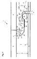
- Fig. 1 shows the structure of the longitudinal edge of an element 1 of a floor covering.
- the middle layer 2 is made of HDF material.
- a decorative layer D is applied on top 4 of the middle layer.
- a counter-pull G is applied on the bottom 6 of the middle layer 2.
- the floor element 1 is laid on the floor in the installed state.
- a groove 10 is incorporated in a side surface 8 of the middle layer 2.
- a complementary spring 3 is worked out.
- This groove 10 is according to Fig. 1 designed so that it receives a displaced state, a spring 3 of a second element, so that the two connected elements are secured against vertical movement and against a horizontal pulling apart.
- the groove 10 and the spring 3 are each incorporated in the longitudinal edges of the element 1.
- Fig. 2 shows a comparable arrangement, but for a transverse edge of an element.
- the thus designed element has a middle layer thickness S of 6 mm, wherein the thickness can be reduced to 5 mm.
- the groove 10 has a short groove cheek 12, which runs parallel to the top 4.
- the thickness of this groove cheek 12 is based on the thickness S of the middle layer 23 to 24% of the thickness S.
- a first end of the short groove cheek 12 ends at the groove bottom 14.
- a second end of the short groove cheek 12 ends at or in the side surface 8.
- Der Groove base 14 extends perpendicular to the upper side 4 over 11 to 12% of the thickness S of the middle layer 2.
- the long groove cheek 16 sets, which extends beyond the short groove cheek 12 out to a free end 18.
- a first portion 20 of the long groove cheek 16 extends from the groove bottom 14 to the bottom 6 and ends at the second portion 22 a, which runs parallel to the bottom 6.
- the second section 22a having a thickness of 33% of the middle layer thickness S, merges into a weaker third section 22b whose thickness is 30% of the middle layer thickness S.
- the corresponding with the groove 10 spring 3 is located after the joining of two complementary elements 1 on the stronger second portion 22a.
- the weaker third portion 22b has no contact with the spring 3, therefore it allows a simpler displacement of second elements 1 parallel to its longitudinal axis.
- the fourth portion 24 has a maximum strength that does not exceed 75% of the thickness S of the middle layer.
- the distance from the end of the third portion 22b to the free end of the long groove cheek 16 is referred to as the width 24a of the fourth portion 24.
- the element 1 has at the side edges 8 abutting surfaces 26.
- the abutment surfaces each extend from the short groove cheek 12 to the upper side 4 of the element 2 and from the upper side 28 of the spring 3 to the upper side 4 of the element 1.
- the abutting surfaces 26 face each other in the case of corresponding or interlinked elements 1, but they run not always straight. They may have recesses or be arranged at a distance from each other.
- the spring 3 extends with a freely projecting part 5 of the abutting surface 26 of the element 1 to a free end 30, which faces the groove bottom 14.
- the first contact surface 12a may be arranged in a plane with the upper side 28 or extend at a distance therefrom.
- the underside 32 of the spring 3 extends substantially corresponding to the sections 1 to 4 of the long groove cheek 16.
- the length of the second bearing surface 22a between the spring 3 and the second portion 22a of the long groove cheek is about 30% of Length of the second section of the long groove cheek.
- the portion of the underside 32, which spans the sections 22 and 22b be flat, so that in the assembled state, the bottom 32 abuts the portion 22a, the portion 22b but has a distance.
- the fourth section 24 of the longer groove cheek 16 is received in a recess 34 with the free end 18.
- the recess 34 is bounded by a lower abutment surface 36 and by portions of the underside 32 of the spring 3.
- the underside 32 is divided over the fourth portion 24 of the longer groove cheek in three sections 32a, 32b and 32c.
- the portion 32a extends from the bottom 32 of the spring 3 to the top 4 of the element 1.
- the portion 32b connects, which extends approximately horizontally.
- Section 32b terminates at its other end at portion 32c, which is inclined downwardly to the bottom 6 of the element 1 and terminates at the lower abutment surface 36.
- the overall length of the spring 3 extends from the lower abutment surface 36 to the free end 30 of the spring.
- An angle ⁇ is bounded by a line 38, the the top 28 of the spring 3 continues horizontally and parallel with respect to the top 4 of the element 1 and from a straight line 24b extending from the intersection of the line 38 with the abutment surface 26 up to the interface between the section 32a and the section 32b ,
- the angle ⁇ is 13 ° for a longitudinal edge profile and 16 ° for a transverse or end edge profile (cf. Fig. 2 ).
- the width 24a of the fourth portion 24 is 1: 2 in relation to the straight line 24b. The dimensioning of the width 24a depends on the shear tensile strength of the middle layer and the loading parameters of the laid surfaces.
- the spring 3 has in its free portion a thickness of 43 to 44%, based on the thickness of the middle layer of the element on.
- the length of the first contact surface 12a between the spring and the short groove cheek is 23 to 24% of the thickness of the middle layer.
- the length of the first contact surface 12a between spring and short groove cheek is about 15% of the thickness of the middle layer.
- the above design rules for the spring, its strength and the relationship of the contact surfaces to each other ensures that the connection is easy to produce by pivoting and holds reliably.
- the design rules are based on uncoated HDF boards to be glued with dispersion adhesives with densities of 850 to 950 kg / m 2 with typical transverse tensile strengths of approx. 1.4 to 1.8 N / mm 2 , with typical bending strengths of 40 to 50 N / mm 2 and on usual loads of the laid surface in living space usual size of up to 70 m 2 .
- the total thickness of the floor element may exceed 6 mm if a decorative layer D is applied to the top 4 and / or a backsheet layer is applied to the bottom 6 of the middle layer 2, and these layers exceed the thickness of a decorative paper.
- a decorative layer D is applied to the top 4 and / or a backsheet layer is applied to the bottom 6 of the middle layer 2, and these layers exceed the thickness of a decorative paper.
- cork and linoleum are processed in thicker layers of about 2 mm.
- bearing surfaces 12a and 22a are sufficient for vertical positioning of the tongue and groove joint.
- reduced bearing surfaces take into account a displacement of the verkuppelten transverse edge profile, which is necessary during assembly.
- the angle ⁇ in conjunction with the dimension 24a and the consequent dimension 24b take into account the material properties of the middle layer and the superimposed loads of a laid floor. Their exact coordination and their relationship to each other, as well as the absolute dimension 24a ensure optimum coordination between the material properties, the middle layer thickness and the loads of the coupling profile by a laid floor.
- An element according to the invention is usually rectangular in shape. It has the above-described groove on a longitudinal edge ( Fig.1 ) on. According to a common embodiment, one longitudinal edge with the above-described groove and a further longitudinal edge with the complementary spring are each designed. In addition, it has a prescribed groove on a transverse edge ( Fig.2 ) on. There is in each case a transverse edge provided with the above-described groove and a further transverse edge with the complementary spring.
Landscapes
- Engineering & Computer Science (AREA)
- Architecture (AREA)
- Civil Engineering (AREA)
- Structural Engineering (AREA)
- Floor Finish (AREA)
- Materials For Medical Uses (AREA)
Claims (11)
- Elément pour un revêtement de sol avec une couche centrale (2) avec une couche de couverture (D) et éventuellement une contrepartie (G) en matériau rigide, en particulier en matériau dérivé du bois, avec un profilé d'accouplement élaboré à partir de la couche centrale pour l'accouplement d'autres éléments de même type, le profilé d'accouplement étant formé à la façon d'un assemblage par rainure et languette et étant placé sur au moins deux arêtes de l'élément,- l'élément présentant au moins une première arête longitudinale avec une rainure (10) qui a une joue de rainure longue (16) et une joue de rainure courte (12), et la rainure (10) étant constituée de telle sorte que, à l'état posé, elle reçoit une languette (3) d'un deuxième élément, de sorte que les deux éléments reliés sont bloqués contre un mouvement vertical et contre un étirement horizontal,- la couche centrale (2) de l'élément présentant une épaisseur (S) pouvant atteindre 6 mm,- la joue de rainure longue (16), rapportée au côté inférieur (6) de la couche centrale (2), étant coudée, un premier tronçon (20) qui est disposé sous la joue de rainure courte (12) étant incliné depuis le fond de rainure (14) vers le côté inférieur (6), un deuxième tronçon (22a) qui se raccorde au premier tronçon (20) étant disposé essentiellement parallèlement au côté inférieur (6), un troisième tronçon (22b) qui est disposé parallèlement au deuxième tronçon (22a) et un quatrième tronçon (24) qui se raccorde vers l'extrémité libre (18) de la joue de rainure longue (16) au troisième tronçon (22b) montant en direction de la partie supérieure (4) de l'élément,- le quatrième tronçon (24) de la joue de rainure longue (16) s'étendant depuis l'extrémité du troisième tronçon (22b) jusqu'à l'extrémité libre de la joue de rainure longue (16),- l'élément (1) présentant des surfaces de jointure (26) qui s'étendent respectivement depuis la joue de rainure courte (12) jusqu'au côté supérieur (4) de l'élément (1), et depuis le côté supérieur (28) de la languette (3) jusqu'au côté supérieur (4) de l'élément (1) et,- sous l'extrémité libre (30) de la languette (3), le côté inférieur (32) de la languette étant disposé essentiellement en correspondance avec les quatre tronçons de la joue de rainure longue (16), le côté inférieur (32) de la languette présentant, au-dessus du quatrième tronçon (24) de la joue de rainure longue (16), un premier tronçon (32a) qui est incliné depuis le côté inférieur (32) de la languette (3) vers le côté supérieur (4) de l'élément (1), un deuxième tronçon (32b) se raccordant à ce premier tronçon et étant disposé essentiellement parallèlement au côté supérieur (4) de l'élément (1),- une ligne (38), qui prolonge le côté supérieur (28) de la languette (3) horizontalement et parallèlement au côté supérieur (4) de l'élément (1), et une droite (24b) qui s'étend depuis l'interface de la ligne (38) avec la surface de jointure (26) de la languette jusqu'à l'interface entre le premier tronçon (32a) de la languette et le deuxième tronçon (32b) de la languette enfermant un angle (α), et- la joue de rainure courte (12) étant disposée essentiellement parallèlement au côté supérieur (4) de l'élément,caractérisé en ce que- la distance entre le côté inférieur de la joue de rainure courte (12) et le côté supérieur (4) de la couche centrale (2) représente 23 à 24% de l'épaisseur de la couche centrale (2),- l'épaisseur du deuxième tronçon (22a) de la joue de rainure longue (16) représente 33% de l'épaisseur (S) de la couche centrale (2) de l'élément ;- la joue de rainure longue présente cependant une épaisseur de 75% au maximum de l'épaisseur (S) de la couche centrale (2),- la languette présente une épaisseur de 43 à 44% rapportée à l'épaisseur (S) de la couche centrale, et- la longueur de la première surface de contact (12a) entre la languette et la joue de rainure courte (12) représentant au maximum 30% de la longueur totale de l'extrémité libre de la languette (3),- la longueur de la deuxième surface de contact (22a) entre la languette et le deuxième tronçon (22a) de la joue de rainure longue (16) représentant au maximum 50% de la longueur du deuxième tronçon (22a) de la joue de rainure longue (16), et- la distance (24a), qui correspond à la largeur du quatrième tronçon (24), par rapport à la distance (24b) qui s'étend du point d'intersection de la surface de jointure (26) avec le côté supérieur (28) de la languette (3) jusqu'à la transition du premier tronçon (32a) de la languette vers le deuxième tronçon (32b) de la languette (3), étant dans un rapport de 1:2, et- l'angle (α), qui est limité par la ligne (38) et la droite (24a), atteignant 16°.
- Elément selon la revendication 1, caractérisé en ce que les moyens d'accouplement sont constitués en tant que raccordement pivotant.
- Elément selon la revendication 1, caractérisé en ce que le matériau rigide est un matériau dérivé du bois, en particulier un panneau de fibres, de préférence un panneau de fibre de densité moyenne ou de densité élevée.
- Elément selon la revendication 1, caractérisé en ce que les arêtes longitudinales et les arêtes transversales présentent un profilé différent.
- Elément selon la revendication 1, caractérisé en ce que la languette (3) des arêtes longitudinales et des arêtes transversales présentent une épaisseur allant jusqu'à 44% de l'épaisseur (S) de la couche centrale.
- Elément selon la revendication 1, caractérisé en ce que l'angle (α) atteint jusqu'à 13° pour l'arête longitudinale et jusqu'à 16° pour l'arête transversale.
- Elément selon la revendication 1, caractérisé en ce que l'épaisseur du deuxième tronçon (22a) représente 33% de l'épaisseur (S) de la couche centrale (2) de l'élément et se transforme en un tronçon plus faible (22b) dont l'épaisseur, rapportée au côté inférieur (6) de la couche centrale (2), représente 30% de l'épaisseur (S) de la couche centrale de l'élément.
- Elément selon la revendication 1, caractérisé en ce que le premier tronçon (20) est disposé en tant que droite depuis le fond de rainure (14) vers le deuxième tronçon (22a) de la joue de rainure longue (16).
- Elément selon la revendication 1, caractérisé en ce que, entre la joue de rainure courte (12) et la joue de rainure longue (16), est disposé un fond de rainure (14) qui s'étend essentiellement perpendiculairement au côté supérieur (4) de l'élément.
- Elément selon la revendication 9, caractérisé en ce que le fond de rainure (14) représente 11 à 12% de l'épaisseur (S) de la couche centrale (2).
- Elément selon la revendication 1, caractérisé en ce que, sur le côté supérieur (4) de l'élément, est placée une couche décorative (D), en particulier un papier décoratif, une couche de liège, une couche de linoleum ou une couche de contreplacage.
Applications Claiming Priority (4)
| Application Number | Priority Date | Filing Date | Title |
|---|---|---|---|
| DE20313942 | 2003-09-05 | ||
| DE20313942U | 2003-09-05 | ||
| DE10349525A DE10349525A1 (de) | 2003-09-05 | 2003-10-22 | Element für einen Fußbodenbelag mit einer dünnen Mittelschicht |
| DE10349525 | 2003-10-22 |
Publications (3)
| Publication Number | Publication Date |
|---|---|
| EP1512807A1 EP1512807A1 (fr) | 2005-03-09 |
| EP1512807B1 EP1512807B1 (fr) | 2008-05-07 |
| EP1512807B9 true EP1512807B9 (fr) | 2008-09-10 |
Family
ID=34137330
Family Applications (1)
| Application Number | Title | Priority Date | Filing Date |
|---|---|---|---|
| EP04021142A Expired - Lifetime EP1512807B9 (fr) | 2003-09-05 | 2004-09-06 | Element avec couche centrale mince pour revêtement de sol |
Country Status (3)
| Country | Link |
|---|---|
| EP (1) | EP1512807B9 (fr) |
| AT (1) | ATE394559T1 (fr) |
| DE (1) | DE502004007033D1 (fr) |
Families Citing this family (3)
| Publication number | Priority date | Publication date | Assignee | Title |
|---|---|---|---|---|
| BE1021929B1 (nl) | 2014-07-04 | 2016-01-27 | Unilin Bvba | Vloerpaneel |
| EP3216941B1 (fr) * | 2016-03-10 | 2019-10-09 | tilo GmbH | Plaque de revêtement de sol et revêtement de sol |
| BE1024734B1 (nl) * | 2016-11-10 | 2018-06-19 | Ivc Bvba | Vloerpaneel en werkwijze voor het vervaardigen van een vloerpaneel |
Family Cites Families (6)
| Publication number | Priority date | Publication date | Assignee | Title |
|---|---|---|---|---|
| CH562377A5 (en) * | 1971-11-29 | 1975-05-30 | Hebgen Heinrich | Form-locked building panel joint connection - with shaped end of one fitting into lipped rounded edge channel of next |
| DE9109031U1 (de) * | 1991-07-22 | 1991-12-12 | Baustoff- und Holzhandel Martin Wimmer, 8221 Waging | Fußbodendiele aus Verbundholz |
| BE1010487A6 (nl) * | 1996-06-11 | 1998-10-06 | Unilin Beheer Bv | Vloerbekleding bestaande uit harde vloerpanelen en werkwijze voor het vervaardigen van dergelijke vloerpanelen. |
| SE512290C2 (sv) * | 1998-06-03 | 2000-02-28 | Valinge Aluminium Ab | Låssystem för mekanisk hopfogning av golvskivor samt golvskiva försedd med låssystemet |
| SE517478C2 (sv) * | 1999-04-30 | 2002-06-11 | Valinge Aluminium Ab | Låssystem för mekanisk hofogning av golvskivor, golvskiva försedd med låssystemet samt metod för framställning av mekaniskt hopfogningsbara golvskivor |
| SE517183C2 (sv) * | 2000-01-24 | 2002-04-23 | Valinge Aluminium Ab | Låssystem för mekanisk hopfogning av golvskivor, golvskiva försedd med låssystemet och metod för framställning av sådana golvskivor |
-
2004
- 2004-09-06 EP EP04021142A patent/EP1512807B9/fr not_active Expired - Lifetime
- 2004-09-06 DE DE502004007033T patent/DE502004007033D1/de not_active Expired - Lifetime
- 2004-09-06 AT AT04021142T patent/ATE394559T1/de active
Also Published As
| Publication number | Publication date |
|---|---|
| ATE394559T1 (de) | 2008-05-15 |
| EP1512807B1 (fr) | 2008-05-07 |
| EP1512807A1 (fr) | 2005-03-09 |
| DE502004007033D1 (de) | 2008-06-19 |
Similar Documents
| Publication | Publication Date | Title |
|---|---|---|
| DE602004010914T3 (de) | Satz von Fussbodenpaneelen | |
| DE69916666T2 (de) | Rechteckige Bodenplatte | |
| DE69926608T2 (de) | Fussbodensystem umfassend Fussbodenplatten mit Führungsmitteln | |
| DE10206877B4 (de) | Paneel, insbesondere Fussbodenpaneel | |
| DE10159284B4 (de) | Gebäudeplatte, insbesondere Bodenpaneel | |
| WO2002001018A1 (fr) | Plaque de revetement de sol | |
| DE202006020940U1 (de) | Mechanisches Verriegelungssystem für Bodenpaneele | |
| DE20116962U1 (de) | Verbindungssystem für Fußbodendielen und Dielen hierfür | |
| EP1350904A2 (fr) | Planches de plancher | |
| DE10243196A1 (de) | Paneele mit Verbindungsklammer | |
| EP1203855A2 (fr) | Panneau | |
| DE10013684A1 (de) | Verbindungssystem für Platten | |
| DE20108358U1 (de) | Laminat, insbesondere Fußbodenlaminat | |
| DE10006748A1 (de) | Wieder lösbares Verbindungsprofil für Fußbodendielen, Paneele oder ähnliche Bauteile | |
| EP1512807B1 (fr) | Element avec couche centrale mince pour revêtement de sol | |
| DE202004021867U1 (de) | Mechanische Verriegelung für Bodenpaneele | |
| DE2258161A1 (de) | Bauplatte mit einer aus marmor bestehenden sichtflaeche | |
| DE20121196U1 (de) | Gebäudeplatte, insbesondere Bodenpaneel | |
| EP1700966A1 (fr) | Cheville plate pour fixer des planches en bois côte à côte | |
| DE10349525A1 (de) | Element für einen Fußbodenbelag mit einer dünnen Mittelschicht | |
| WO2000074911A1 (fr) | Lamelle de parquet, son utilisation pour produire un panneau ou un element de parquet, et element de parquet ainsi obtenu ainsi que procede pour produire une lamelle de parquet | |
| DE4123682A1 (de) | Wand-, decken- oder balkenelement aus verleimten holzeinzelelementen sowie daraus hergestellte vollholzwand | |
| DE10154767A1 (de) | Fussbodenpaneel | |
| DE10302961B4 (de) | Wandabschlussleiste | |
| DE102007036267A1 (de) | Flächenelastischer Boden und zugehörige Fußbodenplatte |
Legal Events
| Date | Code | Title | Description |
|---|---|---|---|
| PUAI | Public reference made under article 153(3) epc to a published international application that has entered the european phase |
Free format text: ORIGINAL CODE: 0009012 |
|
| AK | Designated contracting states |
Kind code of ref document: A1 Designated state(s): AT BE BG CH CY CZ DE DK EE ES FI FR GB GR HU IE IT LI LU MC NL PL PT RO SE SI SK TR |
|
| AX | Request for extension of the european patent |
Extension state: AL HR LT LV MK |
|
| 17P | Request for examination filed |
Effective date: 20050829 |
|
| AKX | Designation fees paid |
Designated state(s): AT BE BG CH CY CZ DE DK EE ES FI FR GB GR HU IE IT LI LU MC NL PL PT RO SE SI SK TR |
|
| 17Q | First examination report despatched |
Effective date: 20061124 |
|
| GRAP | Despatch of communication of intention to grant a patent |
Free format text: ORIGINAL CODE: EPIDOSNIGR1 |
|
| GRAS | Grant fee paid |
Free format text: ORIGINAL CODE: EPIDOSNIGR3 |
|
| GRAA | (expected) grant |
Free format text: ORIGINAL CODE: 0009210 |
|
| AK | Designated contracting states |
Kind code of ref document: B1 Designated state(s): AT BE BG CH CY CZ DE DK EE ES FI FR GB GR HU IE IT LI LU MC NL PL PT RO SE SI SK TR |
|
| REG | Reference to a national code |
Ref country code: GB Ref legal event code: FG4D Free format text: NOT ENGLISH |
|
| REG | Reference to a national code |
Ref country code: CH Ref legal event code: EP Ref country code: CH Ref legal event code: NV Representative=s name: PATENTANWALT DIPL. ING. WOLFGANG HEISEL |
|
| REG | Reference to a national code |
Ref country code: IE Ref legal event code: FG4D Free format text: LANGUAGE OF EP DOCUMENT: GERMAN |
|
| REF | Corresponds to: |
Ref document number: 502004007033 Country of ref document: DE Date of ref document: 20080619 Kind code of ref document: P |
|
| PG25 | Lapsed in a contracting state [announced via postgrant information from national office to epo] |
Ref country code: SI Free format text: LAPSE BECAUSE OF FAILURE TO SUBMIT A TRANSLATION OF THE DESCRIPTION OR TO PAY THE FEE WITHIN THE PRESCRIBED TIME-LIMIT Effective date: 20080507 |
|
| PG25 | Lapsed in a contracting state [announced via postgrant information from national office to epo] |
Ref country code: NL Free format text: LAPSE BECAUSE OF FAILURE TO SUBMIT A TRANSLATION OF THE DESCRIPTION OR TO PAY THE FEE WITHIN THE PRESCRIBED TIME-LIMIT Effective date: 20080507 Ref country code: FI Free format text: LAPSE BECAUSE OF FAILURE TO SUBMIT A TRANSLATION OF THE DESCRIPTION OR TO PAY THE FEE WITHIN THE PRESCRIBED TIME-LIMIT Effective date: 20080507 |
|
| REG | Reference to a national code |
Ref country code: ES Ref legal event code: FG2A Ref document number: 2305633 Country of ref document: ES Kind code of ref document: T3 |
|
| NLV1 | Nl: lapsed or annulled due to failure to fulfill the requirements of art. 29p and 29m of the patents act | ||
| PG25 | Lapsed in a contracting state [announced via postgrant information from national office to epo] |
Ref country code: PL Free format text: LAPSE BECAUSE OF FAILURE TO SUBMIT A TRANSLATION OF THE DESCRIPTION OR TO PAY THE FEE WITHIN THE PRESCRIBED TIME-LIMIT Effective date: 20080507 |
|
| REG | Reference to a national code |
Ref country code: IE Ref legal event code: FD4D |
|
| PG25 | Lapsed in a contracting state [announced via postgrant information from national office to epo] |
Ref country code: SE Free format text: LAPSE BECAUSE OF FAILURE TO SUBMIT A TRANSLATION OF THE DESCRIPTION OR TO PAY THE FEE WITHIN THE PRESCRIBED TIME-LIMIT Effective date: 20080807 Ref country code: PT Free format text: LAPSE BECAUSE OF FAILURE TO SUBMIT A TRANSLATION OF THE DESCRIPTION OR TO PAY THE FEE WITHIN THE PRESCRIBED TIME-LIMIT Effective date: 20081007 Ref country code: IE Free format text: LAPSE BECAUSE OF FAILURE TO SUBMIT A TRANSLATION OF THE DESCRIPTION OR TO PAY THE FEE WITHIN THE PRESCRIBED TIME-LIMIT Effective date: 20080507 Ref country code: CZ Free format text: LAPSE BECAUSE OF FAILURE TO SUBMIT A TRANSLATION OF THE DESCRIPTION OR TO PAY THE FEE WITHIN THE PRESCRIBED TIME-LIMIT Effective date: 20080507 Ref country code: DK Free format text: LAPSE BECAUSE OF FAILURE TO SUBMIT A TRANSLATION OF THE DESCRIPTION OR TO PAY THE FEE WITHIN THE PRESCRIBED TIME-LIMIT Effective date: 20080507 |
|
| PG25 | Lapsed in a contracting state [announced via postgrant information from national office to epo] |
Ref country code: SK Free format text: LAPSE BECAUSE OF FAILURE TO SUBMIT A TRANSLATION OF THE DESCRIPTION OR TO PAY THE FEE WITHIN THE PRESCRIBED TIME-LIMIT Effective date: 20080507 Ref country code: RO Free format text: LAPSE BECAUSE OF FAILURE TO SUBMIT A TRANSLATION OF THE DESCRIPTION OR TO PAY THE FEE WITHIN THE PRESCRIBED TIME-LIMIT Effective date: 20080507 |
|
| PLBE | No opposition filed within time limit |
Free format text: ORIGINAL CODE: 0009261 |
|
| STAA | Information on the status of an ep patent application or granted ep patent |
Free format text: STATUS: NO OPPOSITION FILED WITHIN TIME LIMIT |
|
| BERE | Be: lapsed |
Owner name: TILO GMBH Effective date: 20080930 |
|
| 26N | No opposition filed |
Effective date: 20090210 |
|
| PG25 | Lapsed in a contracting state [announced via postgrant information from national office to epo] |
Ref country code: EE Free format text: LAPSE BECAUSE OF FAILURE TO SUBMIT A TRANSLATION OF THE DESCRIPTION OR TO PAY THE FEE WITHIN THE PRESCRIBED TIME-LIMIT Effective date: 20080507 Ref country code: BG Free format text: LAPSE BECAUSE OF FAILURE TO SUBMIT A TRANSLATION OF THE DESCRIPTION OR TO PAY THE FEE WITHIN THE PRESCRIBED TIME-LIMIT Effective date: 20080807 Ref country code: MC Free format text: LAPSE BECAUSE OF NON-PAYMENT OF DUE FEES Effective date: 20080930 |
|
| REG | Reference to a national code |
Ref country code: CH Ref legal event code: PCAR Free format text: PATENTANWALT DIPL.-ING. (UNI.) WOLFGANG HEISEL;HAUPTSTRASSE 14;8280 KREUZLINGEN (CH) |
|
| GBPC | Gb: european patent ceased through non-payment of renewal fee |
Effective date: 20080906 |
|
| REG | Reference to a national code |
Ref country code: FR Ref legal event code: ST Effective date: 20090529 |
|
| PG25 | Lapsed in a contracting state [announced via postgrant information from national office to epo] |
Ref country code: BE Free format text: LAPSE BECAUSE OF NON-PAYMENT OF DUE FEES Effective date: 20080930 |
|
| PG25 | Lapsed in a contracting state [announced via postgrant information from national office to epo] |
Ref country code: FR Free format text: LAPSE BECAUSE OF NON-PAYMENT OF DUE FEES Effective date: 20080930 |
|
| PG25 | Lapsed in a contracting state [announced via postgrant information from national office to epo] |
Ref country code: GB Free format text: LAPSE BECAUSE OF NON-PAYMENT OF DUE FEES Effective date: 20080906 |
|
| PG25 | Lapsed in a contracting state [announced via postgrant information from national office to epo] |
Ref country code: CY Free format text: LAPSE BECAUSE OF FAILURE TO SUBMIT A TRANSLATION OF THE DESCRIPTION OR TO PAY THE FEE WITHIN THE PRESCRIBED TIME-LIMIT Effective date: 20080507 Ref country code: HU Free format text: LAPSE BECAUSE OF FAILURE TO SUBMIT A TRANSLATION OF THE DESCRIPTION OR TO PAY THE FEE WITHIN THE PRESCRIBED TIME-LIMIT Effective date: 20081108 Ref country code: LU Free format text: LAPSE BECAUSE OF NON-PAYMENT OF DUE FEES Effective date: 20080906 |
|
| PG25 | Lapsed in a contracting state [announced via postgrant information from national office to epo] |
Ref country code: TR Free format text: LAPSE BECAUSE OF FAILURE TO SUBMIT A TRANSLATION OF THE DESCRIPTION OR TO PAY THE FEE WITHIN THE PRESCRIBED TIME-LIMIT Effective date: 20080507 |
|
| PG25 | Lapsed in a contracting state [announced via postgrant information from national office to epo] |
Ref country code: GR Free format text: LAPSE BECAUSE OF FAILURE TO SUBMIT A TRANSLATION OF THE DESCRIPTION OR TO PAY THE FEE WITHIN THE PRESCRIBED TIME-LIMIT Effective date: 20080808 |
|
| PGFP | Annual fee paid to national office [announced via postgrant information from national office to epo] |
Ref country code: ES Payment date: 20150923 Year of fee payment: 12 Ref country code: CH Payment date: 20150922 Year of fee payment: 12 |
|
| PGFP | Annual fee paid to national office [announced via postgrant information from national office to epo] |
Ref country code: AT Payment date: 20150921 Year of fee payment: 12 |
|
| PGFP | Annual fee paid to national office [announced via postgrant information from national office to epo] |
Ref country code: IT Payment date: 20150925 Year of fee payment: 12 Ref country code: DE Payment date: 20150929 Year of fee payment: 12 |
|
| REG | Reference to a national code |
Ref country code: DE Ref legal event code: R119 Ref document number: 502004007033 Country of ref document: DE |
|
| REG | Reference to a national code |
Ref country code: CH Ref legal event code: PL |
|
| REG | Reference to a national code |
Ref country code: AT Ref legal event code: MM01 Ref document number: 394559 Country of ref document: AT Kind code of ref document: T Effective date: 20160906 |
|
| PG25 | Lapsed in a contracting state [announced via postgrant information from national office to epo] |
Ref country code: CH Free format text: LAPSE BECAUSE OF NON-PAYMENT OF DUE FEES Effective date: 20160930 Ref country code: LI Free format text: LAPSE BECAUSE OF NON-PAYMENT OF DUE FEES Effective date: 20160930 Ref country code: DE Free format text: LAPSE BECAUSE OF NON-PAYMENT OF DUE FEES Effective date: 20170401 |
|
| PG25 | Lapsed in a contracting state [announced via postgrant information from national office to epo] |
Ref country code: IT Free format text: LAPSE BECAUSE OF NON-PAYMENT OF DUE FEES Effective date: 20160906 Ref country code: AT Free format text: LAPSE BECAUSE OF NON-PAYMENT OF DUE FEES Effective date: 20160906 |
|
| PG25 | Lapsed in a contracting state [announced via postgrant information from national office to epo] |
Ref country code: ES Free format text: LAPSE BECAUSE OF NON-PAYMENT OF DUE FEES Effective date: 20160907 |
|
| REG | Reference to a national code |
Ref country code: ES Ref legal event code: FD2A Effective date: 20180627 |