EP1512868A2 - Méthode et dispositif de commande d'un actionneur pour un démarreur - Google Patents
Méthode et dispositif de commande d'un actionneur pour un démarreur Download PDFInfo
- Publication number
- EP1512868A2 EP1512868A2 EP04016882A EP04016882A EP1512868A2 EP 1512868 A2 EP1512868 A2 EP 1512868A2 EP 04016882 A EP04016882 A EP 04016882A EP 04016882 A EP04016882 A EP 04016882A EP 1512868 A2 EP1512868 A2 EP 1512868A2
- Authority
- EP
- European Patent Office
- Prior art keywords
- starter
- actuator
- control device
- control
- signal
- Prior art date
- Legal status (The legal status is an assumption and is not a legal conclusion. Google has not performed a legal analysis and makes no representation as to the accuracy of the status listed.)
- Granted
Links
- 238000000034 method Methods 0.000 title claims abstract description 90
- 239000007858 starting material Substances 0.000 title claims abstract description 64
- 230000008569 process Effects 0.000 claims abstract description 29
- 238000004590 computer program Methods 0.000 claims description 12
- 238000002485 combustion reaction Methods 0.000 claims description 7
- 230000004044 response Effects 0.000 claims description 5
- 230000003213 activating effect Effects 0.000 claims description 3
- 230000005540 biological transmission Effects 0.000 claims description 3
- 230000008878 coupling Effects 0.000 claims description 3
- 238000010168 coupling process Methods 0.000 claims description 3
- 238000005859 coupling reaction Methods 0.000 claims description 3
- 239000003990 capacitor Substances 0.000 claims description 2
- 230000006870 function Effects 0.000 abstract description 2
- 230000004913 activation Effects 0.000 description 5
- 230000008901 benefit Effects 0.000 description 4
- 230000000295 complement effect Effects 0.000 description 2
- 230000002411 adverse Effects 0.000 description 1
- 230000008859 change Effects 0.000 description 1
- 238000004891 communication Methods 0.000 description 1
- 230000003111 delayed effect Effects 0.000 description 1
- 230000001419 dependent effect Effects 0.000 description 1
- 230000007257 malfunction Effects 0.000 description 1
- 230000002093 peripheral effect Effects 0.000 description 1
- 230000002035 prolonged effect Effects 0.000 description 1
Images
Classifications
-
- F—MECHANICAL ENGINEERING; LIGHTING; HEATING; WEAPONS; BLASTING
- F02—COMBUSTION ENGINES; HOT-GAS OR COMBUSTION-PRODUCT ENGINE PLANTS
- F02N—STARTING OF COMBUSTION ENGINES; STARTING AIDS FOR SUCH ENGINES, NOT OTHERWISE PROVIDED FOR
- F02N11/00—Starting of engines by means of electric motors
- F02N11/08—Circuits specially adapted for starting of engines
-
- F—MECHANICAL ENGINEERING; LIGHTING; HEATING; WEAPONS; BLASTING
- F02—COMBUSTION ENGINES; HOT-GAS OR COMBUSTION-PRODUCT ENGINE PLANTS
- F02N—STARTING OF COMBUSTION ENGINES; STARTING AIDS FOR SUCH ENGINES, NOT OTHERWISE PROVIDED FOR
- F02N11/00—Starting of engines by means of electric motors
- F02N11/08—Circuits specially adapted for starting of engines
- F02N11/0862—Circuits specially adapted for starting of engines characterised by the electrical power supply means, e.g. battery
-
- F—MECHANICAL ENGINEERING; LIGHTING; HEATING; WEAPONS; BLASTING
- F02—COMBUSTION ENGINES; HOT-GAS OR COMBUSTION-PRODUCT ENGINE PLANTS
- F02N—STARTING OF COMBUSTION ENGINES; STARTING AIDS FOR SUCH ENGINES, NOT OTHERWISE PROVIDED FOR
- F02N2300/00—Control related aspects of engine starting
- F02N2300/30—Control related aspects of engine starting characterised by the use of digital means
Definitions
- the invention relates to a control device and a method for driving at least one actuator for a Starter motor of a motor vehicle and a corresponding Computer program and a disk with this Computer program.
- the control unit disclosed therein comprises a control device in the form of a microcontroller with an I / O port for outputting a control signal Actuator or a controlled system in response to a Start command. It also includes a Drive holding device, which between the Control device, that is the microcontroller and the Controlled system is arranged for caching the Control signal after this from the microcontroller was issued. In addition, the control unit includes a feedback device for feeding back a current one State of the drive-holding device back to the Output port of the microcontroller or on the Input of the drive holding device.
- the proposed Drive circuit causes the drive-holding device and therefore also the downstream Actuator by a voltage dip or Reset of the microcontroller no state change experiences.
- a reset the drive-holding device is not off. Was it already turned off before the reset, so it is not turned on by the reset.
- the disadvantage attaches to the fact that the current state of the drive-holding member, which by the feedback Signal is not represented by the microcontroller in his decision on the further control of the Actuator is used after its reset.
- a superposition signal which from the feedback signal and that of the microcontroller formed his output port output drive signal is, via the control of the actuator or the starter after a reset. This dominates during a reset and initialization phase of the microcontroller the previous initial state while after the Initialization of the microcontroller whose drive signal dominated.
- Such a design of the control device of the Control unit offers the advantage of being an unintentional Restarting the actuator after a reset of the Control device is prevented, as long as not all Conditions / criteria are met.
- a reset causes all outputs of the controller connected to ground become.
- the controller output control signal for the actuator is after a Reset only from the drive-holding device on Maintained input of the actuator.
- the discharge relation is Hold time set so short that they are in the Regarding the unwanted prolonged switching on the Actuator is irrelevant.
- the proposed procedure thus causes an unintentional activation of the Actuator or the starter motor after a Restarting the control device is prevented.
- it is designed so that it controls the drive of the starter over the actuator not only during one first, but also during a selectable number subsequent voltage dips and related Resets the controller maintains.
- a first advantageous embodiment of claimed controller has this at least one Shutdown output on to turn off the starter via the Actuator, priority and independent of the state of the Switch-on output of the control device.
- An unintentional Turning on the starter according to the invention thereby prevents the control device from activating the Not only resumes the actuator after a reset, if the actuator still on the drive-holding device is driven, but if additional criteria are fulfilled. So, in particular, the ignition needs or the ignition is still on, may be a predetermined setpoint speed at the end of Starting process (start-up speed) not yet reached be and the number of so far during the boot process Resets occurred a preset reset threshold have not exceeded.
- the method also includes others Measures to prevent unintentional activation of the starter prevent. So it looks, for example, a redundant Storage of a given by the driver start signal (Terminal 50 signal) or one derived from it Start command in different memory areas or in different microcontrollers, preferably in complementary form before a later review of the To be able to secure the existence of the start command.
- a additional measure against unintentional activation of the starter is that during the boot process then, if a driving condition in the form that the ignition lock is turned on and the current speed of the too starting engine a predetermined start-up speed yet has not reached, is not satisfied, the original Start request of the driver is discarded by the Start command or a stored terminal 50 information is deleted.
- control unit and of the method are the subject of the dependent claims.
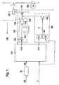
- FIG. 1 shows the control unit 100 according to the invention. It serves to drive at least one actuator 200 for a starter 300 of a motor vehicle (not shown).
- the Controller 100 includes a controller 110, which is preferably designed as a microcontroller. Of the Microcontroller receives one at its input Start request SW, which he, if further conditions (see Step S7 in Figure 2) are satisfied as Start command SB in a memory, preferably a permanent RAM 111, redundant and complementary stores. Of the Microcontroller 110 has a switch-on output E-A, which is connected to a drive holding device 120 is. The output of this drive-holding device 120 leads to the entrance or the base of a first Switching transistor 150 for direct driving a Actuator 200.
- the actuator 200 is preferably a relay, which the starter 300 directly on or off, according to the of the Microcontroller at its switch-on output E-A output control signal.
- the control signal is from the Drive holding device 120 instantaneously to the first Switching transistor 150 forwarded.
- the drive-holding device includes in detail an RC element comprising a capacitor 124 and one parallel thereto switched discharge resistor 126. One end of this Parallel connection is via a diode 122 to the switch-on output E-A connected to the control device 110, while the other end of this parallel connection to ground is switched.
- the drive holding device comprises 120 a decoupling resistor 128 to Coupling of the non-grounded end of the RC element 124, 126 to the first switching transistor 150th or the actuator 200.
- the current state of the drive-holding device 120 that is their digital input or Off state or its state of charge in a realization as an RC element on the microcontroller, preferably via an analog-to-digital converter (not shown), fed back.
- the tap of the Feedback device 130 between the collector of the first Switching transistor 150 and the actuator 200 located.
- the power-on output E-A of the microcontroller 110 connected to ground is switched off, the starter 300 via the Drive holding device 120 and the actuator 200.
- this off signal is from the drive-holding device only delayed with the actuator passed to the reset time of the calculator too bridged.
- the microcontroller 110 preferably at least one turn-off output A-A.
- One Switch-off signal at this output then switches the starter 300 immediately.
- a release signal F at Automatic transmissions the parking / normal signal and at Manual gearboxes the coupling signal to the hardware Shutdown of the starter is present.
- Such a circuit logic includes the controller a turn-off logic module 160, which is an OR gate 162 and a second switching transistor 164 having.
- a first input E1 of the OR gate 162 receives the high-active OFF signal of the Microcontroller 110 and a second input E2 of the OR gate 162 receives the low-active enable signal F.
- This Both input signals are through the OR gate 162 logically linked so that at its output a high level is present when one of the microcontroller 110 via his Off signal A-A issued Ausschaltjan for the Starter 300 is present or if the enable signal F is not is low-active.
- a second switching transistor 164 is driven, the between ground and the input of the first switching transistor 150 is switched. With the help of this second Switching transistor becomes the input of the first Switching transistor 150 in response to the output signal A of the OR gate 162 connected to ground, if the Starter 300 should be turned off.
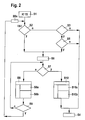
- Step S1 To start the engine of a motor vehicle activates the Driver first the ignition lock of his motor vehicle, putting this into a first possible position, represented by a terminal 15 signal, brings (Step S1). Subsequently, this will check inventive method in the context of an initialization in a second method step S2, the presence of a Plurality of conditions. In these conditions will checked if 1) a starter of the vehicle to start the Motors possibly from a previous boot process is still active, if 2) a so-called start command whose Generation is explained below, is still active and whether 3) the contents of a reset counter is less than one predetermined threshold is. Conditions 1) and 2) both are mandatory; 3) condition optional.
- Step S2 For a new or first time Starting the vehicle is already the first mentioned Conditions not met, which has the consequence that the two others, with the first AND-linked condition. no longer need to be tested. In this case If the query according to method step S2 with "no" answered and the procedure then checks in one Step S3, whether the driver does not use the ignition only in the first position for switching on the ignition, but also in a third position to activate the Starters has turned.
- One of the driver externally uttered start request is the controller 110 by a active so-called terminal 50 signal is displayed.
- Step S3 detected that the terminal 50 signal or the KL50 signal stored as a start request is no longer active, so the controller 100 goes away from having a boot process in the past already was successfully carried out, so that such a currently no longer necessary.
- the Procedure then goes into normal operation of Internal combustion engine of the vehicle according to method step S4 above. If the terminal 50 signal is still active, then go the method of step S3 after Method step S5, in which is checked whether the speed of the internal combustion engine a predetermined minimum speed falls below or not. Is in Method step S5 found that the speed of the Internal combustion engine greater than the predetermined threshold Sn is in the form of the minimum speed, so will turn assumed that the boot process in the past successfully completed; the procedure then goes into the normal operation in accordance with method step S4.
- Step S5 if it was found in step S5 that the Speed of the internal combustion engine the predetermined Threshold Sn in the form of the minimum speed not yet has reached, then interpreted the controller 100 and in particular, the control device 110 the present Situation as the driver's start request and activates corresponding internal signal; this happens in Step S6.
- Step S7 in turn become a plurality of Conditions checked, which OR-linked together are. Depending on whether at least one of these conditions is satisfied, the starter according to step S8 controlled or it is a currently performed Starting process according to step S10 aborted.
- step S7 it is the question of whether the speed of the Internal combustion engine greater than a predetermined Speed threshold Sn, whether the time during which the in Step S6 activated internal signal "starter active "already longer than a predetermined threshold time St is active or whether a traction between the starter and a wheel of the vehicle, indicated for example by a inlaid gear, consists.
- the starter is either driven for the first time or in maintained its function. Inside the Control device 110 then becomes a so-called start command SB is generated and saved or it remains stored if it has already been saved before. In any case, the start command becomes redundant, that is to say Security reasons spread over several stores, stored.
- the generated according to method step S8a or maintained start command SB is not to be confused with the one generated in step S6 Signal "Starter active". The difference is that the start command SB according to method step S8a only then is met if at least one of the conditions according to Method step S7 is not fulfilled.
- Step S8b of the reset counter As part of the starter control or in the context Maintaining the startup process is in Step S8b of the reset counter once incremented.
- Ignition can be assumed to be the reset counter previously set to zero.
- the status of the reset counter after incrementing according to method step S8b is subsequently in method step S9 with a preset reset counter threshold Sz compared.
- This reset counter threshold represents the maximum number of allowed during a boot process Resets or voltage drops of Control device.
- Step S9 If it is determined in method step S9 that this Threshold sz has not yet been reached, then the Startup process continues. More precisely branched then the procedure into a so-called Starter loop, which then at the beginning of the branched out above method step S7.
- the Starter operation loop comprising the method step S7, S8 and S9 will go through as long as the state of Reset counter smaller than the specified one Counter threshold Sz is and none of the conditions according to Step S7 is met.
- step S9 If, however, it is determined in method step S9 that the Status of the reset counter the default Counter threshold Sz has reached, then the Starting process in the form of the drive loop not further continue; instead, a shutdown of the Actuator 200 for the starter via the output A-A of the Control device 110 and the method branches under the Prerequisite that the previously broken voltage has recovered above the actuator 200, at the beginning of the method step S2 described above. It will be then rechecked if all conditions according to process step S2 are fulfilled. If this is not the case, then leads the method below method step S3 and then proceed as described above. However, everyone should Be satisfied conditions according to step S2, so This means that one already in the past started boot process is not yet completed.
- the control device 110 then generates the signal "starter active" according to method step S6. It then checks the following conditions described above according to method step S7 and controls the drive holder 120 via its E-A output again if none of the dropping conditions according to Step S7 is met. In contrast to that Restarting the engine described above will now be the first Starter according to method step S8 not for the first time rather, it stays activated.
- Step S7 the process branches from Method step S7 after method step S10. There will a possibly still active starting process via the output A-A the controller 110 aborted immediately. The starter is discarded and it is the previously in process step S8a redundantly stored start command now redundant cleared (step S10a).
- step S10b of the reset counter to zero reset.
- Step S10 in principle assumed that the boot process was successful has been terminated and it will therefore follow below Step S4, that is the normal operation, branched.
- the method just described is preferably in the form a computer program for a control device for driving realized by an actuator for a starter.
- a software realization to be Computer program
- Computer program if necessary together with others Computer programs on a computer readable medium is stored.
- the disk may be a floppy disk, a compact disc, a flash memory or act like that.
- the stored on the disk Computer program can then as a product to a customer sold.
Landscapes
- Engineering & Computer Science (AREA)
- Chemical & Material Sciences (AREA)
- Combustion & Propulsion (AREA)
- Mechanical Engineering (AREA)
- General Engineering & Computer Science (AREA)
- Combined Controls Of Internal Combustion Engines (AREA)
- Control Of Electric Motors In General (AREA)
Applications Claiming Priority (2)
| Application Number | Priority Date | Filing Date | Title |
|---|---|---|---|
| DE2003140701 DE10340701A1 (de) | 2003-09-04 | 2003-09-04 | Steuergerät und Verfahren zum Ansteuern von einem Stellglied für einen Startermotor |
| DE10340701 | 2003-09-04 |
Publications (3)
| Publication Number | Publication Date |
|---|---|
| EP1512868A2 true EP1512868A2 (fr) | 2005-03-09 |
| EP1512868A3 EP1512868A3 (fr) | 2006-09-06 |
| EP1512868B1 EP1512868B1 (fr) | 2009-10-14 |
Family
ID=34129639
Family Applications (1)
| Application Number | Title | Priority Date | Filing Date |
|---|---|---|---|
| EP20040016882 Expired - Lifetime EP1512868B1 (fr) | 2003-09-04 | 2004-07-16 | Méthode et dispositif de commande d'un actionneur pour un démarreur |
Country Status (2)
| Country | Link |
|---|---|
| EP (1) | EP1512868B1 (fr) |
| DE (2) | DE10340701A1 (fr) |
Cited By (4)
| Publication number | Priority date | Publication date | Assignee | Title |
|---|---|---|---|---|
| WO2007118756A1 (fr) * | 2006-04-11 | 2007-10-25 | Robert Bosch Gmbh | Procédé et dispositif pour commander le démarreur d'un véhicule automobile |
| CN113467527A (zh) * | 2021-06-28 | 2021-10-01 | 华润电力湖南有限公司 | 执行机构联动方法、装置、dcs系统及存储介质 |
| CN116398348A (zh) * | 2022-11-16 | 2023-07-07 | 百发动力(无锡)有限公司 | 一种发电机组双启动控制方法及系统 |
| CN116753100A (zh) * | 2023-06-13 | 2023-09-15 | 一汽解放汽车有限公司 | 一种车辆起动机控制方法、装置、设备及介质 |
Families Citing this family (3)
| Publication number | Priority date | Publication date | Assignee | Title |
|---|---|---|---|---|
| JP5003768B2 (ja) | 2009-01-16 | 2012-08-15 | 株式会社デンソー | スタータ制御装置 |
| DE102019209805A1 (de) * | 2019-07-04 | 2021-01-07 | Robert Bosch Gmbh | Batteriemodul für ein Kraftfahrzeug und Kraftfahrzeug |
| KR20220130516A (ko) * | 2021-03-18 | 2022-09-27 | 주식회사 엘지에너지솔루션 | 릴레이 제어 장치, 배터리 팩 및 전기 차량 |
Family Cites Families (4)
| Publication number | Priority date | Publication date | Assignee | Title |
|---|---|---|---|---|
| JPH02119674A (ja) * | 1988-10-27 | 1990-05-07 | Kubota Ltd | エンジン始動制御装置 |
| US5252861A (en) * | 1991-07-18 | 1993-10-12 | Eaton Corporation | Starter interlock for electronically controlled vehicle |
| DE19720191C1 (de) * | 1997-05-14 | 1998-04-23 | Siemens Ag | Pufferschaltung für den Ausgang eines Mikroprozessors |
| DE19844454C2 (de) * | 1998-09-28 | 2001-11-29 | Siemens Ag | Steuerschaltung zwischen einem Port eines Mikroprozessors und einem elektrischen Verbraucher und Verfahren zum Aufrechterhalten des momentanen Zustands eines elektrischen Verbrauchers während eines Einbruchs der Versorgungsspannung |
-
2003
- 2003-09-04 DE DE2003140701 patent/DE10340701A1/de not_active Withdrawn
-
2004
- 2004-07-16 DE DE200450010223 patent/DE502004010223D1/de not_active Expired - Lifetime
- 2004-07-16 EP EP20040016882 patent/EP1512868B1/fr not_active Expired - Lifetime
Cited By (5)
| Publication number | Priority date | Publication date | Assignee | Title |
|---|---|---|---|---|
| WO2007118756A1 (fr) * | 2006-04-11 | 2007-10-25 | Robert Bosch Gmbh | Procédé et dispositif pour commander le démarreur d'un véhicule automobile |
| CN113467527A (zh) * | 2021-06-28 | 2021-10-01 | 华润电力湖南有限公司 | 执行机构联动方法、装置、dcs系统及存储介质 |
| CN113467527B (zh) * | 2021-06-28 | 2023-03-24 | 华润电力湖南有限公司 | 执行机构联动方法、装置、dcs系统及存储介质 |
| CN116398348A (zh) * | 2022-11-16 | 2023-07-07 | 百发动力(无锡)有限公司 | 一种发电机组双启动控制方法及系统 |
| CN116753100A (zh) * | 2023-06-13 | 2023-09-15 | 一汽解放汽车有限公司 | 一种车辆起动机控制方法、装置、设备及介质 |
Also Published As
| Publication number | Publication date |
|---|---|
| EP1512868B1 (fr) | 2009-10-14 |
| DE10340701A1 (de) | 2005-03-31 |
| DE502004010223D1 (de) | 2009-11-26 |
| EP1512868A3 (fr) | 2006-09-06 |
Similar Documents
| Publication | Publication Date | Title |
|---|---|---|
| DE102011004545B4 (de) | Leerlaufanhaltevorrichtung, Stromsteuerverfahren, Verschleissmeldeverfahren und Batterieladeverfahren | |
| DE102005004326A1 (de) | Startvorrichtung für einen Verbrennungsmotor mit separatem Einrück- und Startvorgang | |
| EP2462337A1 (fr) | Dispositif pour démarrer un moteur à combustion interne | |
| DE10143454B4 (de) | Einrichtung zur Steuerung eines Fahrzeuges | |
| DE102008012343A1 (de) | Motorstart-Steuervorrichtung | |
| DE102006000114A1 (de) | Hochverlässliches Fahrzeug-Startsteuerungssystem | |
| EP0731879B1 (fr) | Circuit et procede de repetition du demarrage de moteurs a combustion interne | |
| WO2008058626A1 (fr) | Véhicule automobile avec une fonction marche-arrêt pour un moteur thermique, et procédé de fonctionnement correspondant | |
| DE10339464A1 (de) | Kommunikationsfehler-Detektionsverfahren für ein Buskommunikationsnetz in einem Fahrzeug | |
| EP1512868B1 (fr) | Méthode et dispositif de commande d'un actionneur pour un démarreur | |
| EP0326694B1 (fr) | Système de sécurité pour moteur à combustion interne | |
| DE10005778A1 (de) | Schaltungsanordnung für einen Starter eines Kraftfahrzeug-Verbrennungsmotors | |
| DE102014225398B4 (de) | Steuerung eines elektromotors bei betrieb mit unzuverlässiger stromversorgung | |
| EP1462683B1 (fr) | Dispositif et procédé de commande d'un aimant d'arret d'un frein de stationnement d'une boîte de vitesses | |
| DE102014102424A1 (de) | Verfahren zum Betreiben eines Lenksystems | |
| DE102013203186A1 (de) | Verbrennungsmotor-Start-Stopp-Automatik-Steuereinheit | |
| DE102005023818B4 (de) | Anzeigeeinheit für ein elektrifiziertes Schaltgetriebe in einem Fahrzeug | |
| DE4219398A1 (de) | Gepufferte Spannungsversorgung für Bordelektronik | |
| DE102009035181B4 (de) | Motorsteuervorrichtung | |
| EP1434934B1 (fr) | Commande de moteur a combustion interne et procede pour faire fonctionner une commande de moteur a combustion interne | |
| DE19843621A1 (de) | Entladeschaltung für ein kapazitives Stellglied | |
| DE10007610B4 (de) | Verfahren zur Programmierung eines Steuergerätes für ein Kraftfahrzeug | |
| DE19841659B4 (de) | Verfahren zur Steuerung einer Kraftstoffpumpe für ein Kraftfahrzeug | |
| DE19947251A1 (de) | Verfahren und Vorrichtung zur Steuerung von Prozessen in Verbindung mit einem Antrieb | |
| DE10317653A1 (de) | Initialisierung eines Steuergerätes |
Legal Events
| Date | Code | Title | Description |
|---|---|---|---|
| PUAI | Public reference made under article 153(3) epc to a published international application that has entered the european phase |
Free format text: ORIGINAL CODE: 0009012 |
|
| AK | Designated contracting states |
Kind code of ref document: A2 Designated state(s): AT BE BG CH CY CZ DE DK EE ES FI FR GB GR HU IE IT LI LU MC NL PL PT RO SE SI SK TR |
|
| AX | Request for extension of the european patent |
Extension state: AL HR LT LV MK |
|
| PUAL | Search report despatched |
Free format text: ORIGINAL CODE: 0009013 |
|
| AK | Designated contracting states |
Kind code of ref document: A3 Designated state(s): AT BE BG CH CY CZ DE DK EE ES FI FR GB GR HU IE IT LI LU MC NL PL PT RO SE SI SK TR |
|
| AX | Request for extension of the european patent |
Extension state: AL HR LT LV MK |
|
| 17P | Request for examination filed |
Effective date: 20070306 |
|
| AKX | Designation fees paid |
Designated state(s): DE FR GB IT |
|
| 17Q | First examination report despatched |
Effective date: 20070820 |
|
| GRAP | Despatch of communication of intention to grant a patent |
Free format text: ORIGINAL CODE: EPIDOSNIGR1 |
|
| GRAS | Grant fee paid |
Free format text: ORIGINAL CODE: EPIDOSNIGR3 |
|
| GRAA | (expected) grant |
Free format text: ORIGINAL CODE: 0009210 |
|
| AK | Designated contracting states |
Kind code of ref document: B1 Designated state(s): DE FR GB IT |
|
| REG | Reference to a national code |
Ref country code: GB Ref legal event code: FG4D Free format text: NOT ENGLISH |
|
| REF | Corresponds to: |
Ref document number: 502004010223 Country of ref document: DE Date of ref document: 20091126 Kind code of ref document: P |
|
| PLBE | No opposition filed within time limit |
Free format text: ORIGINAL CODE: 0009261 |
|
| STAA | Information on the status of an ep patent application or granted ep patent |
Free format text: STATUS: NO OPPOSITION FILED WITHIN TIME LIMIT |
|
| 26N | No opposition filed |
Effective date: 20100715 |
|
| PGFP | Annual fee paid to national office [announced via postgrant information from national office to epo] |
Ref country code: GB Payment date: 20140721 Year of fee payment: 11 |
|
| GBPC | Gb: european patent ceased through non-payment of renewal fee |
Effective date: 20150716 |
|
| PG25 | Lapsed in a contracting state [announced via postgrant information from national office to epo] |
Ref country code: GB Free format text: LAPSE BECAUSE OF NON-PAYMENT OF DUE FEES Effective date: 20150716 |
|
| REG | Reference to a national code |
Ref country code: FR Ref legal event code: PLFP Year of fee payment: 13 |
|
| REG | Reference to a national code |
Ref country code: FR Ref legal event code: PLFP Year of fee payment: 14 |
|
| PGFP | Annual fee paid to national office [announced via postgrant information from national office to epo] |
Ref country code: FR Payment date: 20170720 Year of fee payment: 14 Ref country code: IT Payment date: 20170721 Year of fee payment: 14 |
|
| PG25 | Lapsed in a contracting state [announced via postgrant information from national office to epo] |
Ref country code: FR Free format text: LAPSE BECAUSE OF NON-PAYMENT OF DUE FEES Effective date: 20180731 |
|
| PG25 | Lapsed in a contracting state [announced via postgrant information from national office to epo] |
Ref country code: IT Free format text: LAPSE BECAUSE OF NON-PAYMENT OF DUE FEES Effective date: 20180716 |
|
| PGFP | Annual fee paid to national office [announced via postgrant information from national office to epo] |
Ref country code: DE Payment date: 20220927 Year of fee payment: 19 |
|
| REG | Reference to a national code |
Ref country code: DE Ref legal event code: R119 Ref document number: 502004010223 Country of ref document: DE |
|
| PG25 | Lapsed in a contracting state [announced via postgrant information from national office to epo] |
Ref country code: DE Free format text: LAPSE BECAUSE OF NON-PAYMENT OF DUE FEES Effective date: 20240201 |