EP1512914A2 - Appareil indicateur avec un dispositif de projection pour application dans des appareils de cuisine - Google Patents
Appareil indicateur avec un dispositif de projection pour application dans des appareils de cuisine Download PDFInfo
- Publication number
- EP1512914A2 EP1512914A2 EP04021125A EP04021125A EP1512914A2 EP 1512914 A2 EP1512914 A2 EP 1512914A2 EP 04021125 A EP04021125 A EP 04021125A EP 04021125 A EP04021125 A EP 04021125A EP 1512914 A2 EP1512914 A2 EP 1512914A2
- Authority
- EP
- European Patent Office
- Prior art keywords
- information
- projection
- display device
- projection device
- kitchen
- Prior art date
- Legal status (The legal status is an assumption and is not a legal conclusion. Google has not performed a legal analysis and makes no representation as to the accuracy of the status listed.)
- Withdrawn
Links
Images


Classifications
-
- F—MECHANICAL ENGINEERING; LIGHTING; HEATING; WEAPONS; BLASTING
- F24—HEATING; RANGES; VENTILATING
- F24C—DOMESTIC STOVES OR RANGES ; DETAILS OF DOMESTIC STOVES OR RANGES, OF GENERAL APPLICATION
- F24C15/00—Details
- F24C15/20—Removing cooking fumes
- F24C15/2021—Arrangement or mounting of control or safety systems
Definitions
- the invention relates to a device for kitchens, in particular an extractor hood, according to the specified in the preamble of claim 1. Art.
- devices for kitchens such as an electric stove, a Dishwasher, an extractor hood, a kitchen scale or the like, known executed with an associated display device for visualizing information are, wherein the information from a display element of the display device are readable.
- From DE 199 23 995 A1 is a household appliance, in particular an electric cooking appliance, with an electrical clock unit powered by an electrical network for display the current time, with a non-volatile electrical, programmable Storage unit communicates known.
- DE 100 57 849 A1 discloses a system for operation, control and Service of household appliances, in particular cookers and extractor hoods known in the as to be controlled facilities cooker and hood over a common interface connected to a data transmission system, thereby the appliances to be controlled cooker and hood with each other and communicate with external control units.
- This is the Possibility of information, program offers and procedures for the facilities to be controlled enter, monitor, control and retrieve. It is intended to monitor the devices to be controlled also via external control units and control and also retrieve information, program offers and procedures to be able to.
- the devices to be controlled are associated with the stove and the control units.
- the information is displayed by means of a visualization element, such as For example, a monitor of a computer or a device display, which in either a visible for an operator front of a household appliance or in the field of vision a work area of an operator is arranged.
- a visualization element such as For example, a monitor of a computer or a device display, which in either a visible for an operator front of a household appliance or in the field of vision a work area of an operator is arranged.
- Is the visualization element arranged in the front area of the household appliance it has a certain space requirement, which may be an undesirable Enlargement of the external dimensions of the household appliance leads. Is this Space not available, is the maximum display area of the visualization element limited so that the displayed information readable only up close are. Is the visualization element as a separate component in the field of view of the operator running with a sufficient display area, it has a space requirement, in a workspace of an operator may not be in the required Way is available and an activity of an operator in one Kitchen adversely affected.
- the present invention is therefore based on the object, a device for kitchens with an associated display device for visualizing information for Provide an operator with information in a simple manner provides visually and preferably only a small space requirement in one Viewing area of the device or no space requirement in a working area of an operator having.
- the device according to the invention for kitchens is advantageously provided with a display device to visualize information being executed by a projection device to project the information to a surface.
- a visualization element such as a monitor of a computer LED display element or the like, in a field of view of a kitchen appliance or a work area or a viewing area of an operator are dispensed with.
- the information can be displayed in a simple manner in one size, that they are from an operator even from greater distances, preferably even at a distance of several meters, are readable without this being to an enlargement a kitchen appliance leads.
- the projection device is connected to a control device which controls the generated information to be visualized.
- a control device which controls the generated information to be visualized.
- This may preferably be a Mechanically or electronically executed clockwork act by means of a time is given and the projection device in analog or digital representation is projected onto a surface, preferably an area in a kitchen area, and so that it can be read by an operator in a simple manner.
- the projection device of the device according to the invention with be connected to another control device, the information of various kitchen appliances, such as an extractor hood, an electric cooker, a microwave oven, a coffee machine, a kitchen scale, or the like receives and the projection device for the corresponding representation on the above-described projection forwards.
- various kitchen appliances such as an extractor hood, an electric cooker, a microwave oven, a coffee machine, a kitchen scale, or the like
- the display device can either be integrated in the device itself or at an alternative embodiment of the device according to the invention as a separate, mobile Be executed component, the mobile version of the display device preferably via a wireless transmission network for receiving the to be projected Information may be associated with a kitchen appliance.
- a wireless transmission network for receiving the to be projected Information may be associated with a kitchen appliance.
- the display device for example, on a floor or on any other storage space can be easily positioned without a workspace the operator, who may be limited, in an undesirable manner and Way to reduce.
- the projection device can have an adjustable projection element, so that the projection beam itself without changing the position of the projection device can be directed to different surfaces.
- the projection device is an optical unit, a lighting means and means for visualizing the information to be displayed, wherein the means for visualization are irradiated by the lighting means.
- This execution the projection device has the advantage that known per se components in the manufacture of the projection device, such as elements of a conventional Projector or the like, can be used back, reducing manufacturing costs the device according to the invention are advantageously low.
- the projection beam of the projection device does not strike the surface perpendicularly, on which the information is visualized, it is especially in the presentation an analog clock provided that the discs in the radiation direction of the bulb the projection device is an optical unit designed as an optical disk downstream, by means of a circular shape of the clock is adjustable.
- a luminous intensity of the luminous means of the projection device can be made variable be this, either depending on a desired default of an operator or depending on a generated via a control program specification can be done, which in particular a representation adapted in each case to the brightness of the place of use the visualized information is possible.
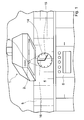
- FIG. 1 and Fig. 2 is a respective hood 1 with an associated Display device 2 or with two associated display devices. 2 or 2A for visualizing information, wherein the display device 2 and the display device 2A each with a projection device 3 for projecting the information on a surface 4 has.
- the area 4 in this case represents a wall a kitchen, which is provided with tiles 5.
- the on the display device 2 or the display device 2A to be visualized information of the hood 1 to any other Surfaces in a kitchen area, such as a sidewall of a kitchen cabinet, a refrigerator, or other kitchen equipment, over the projection device 3 representable.
- the extractor hood 1 is present above a cooktop, not shown a combined cooking furnace device 5 and is arranged with a in Fig. 3 in a highly schematically illustrated longitudinal section running projection device 3 trained.
- the projection device 3 shown in FIG. 3 is connected to the display device 2 according to FIG 1 integrated into the hood 1 in FIG.
- the display device 2A provided as a separate component at the bottom of the hood is positioned over a holding device, not shown, wherein the projection the information in each case either via one of the two display devices 2 or 2A or both at the same time.
- the projection device 3 is presently with a light source 7 and means 8, 9 and 10 for visualizing information, wherein the means 8 to 10 for projection are irradiated by the designed as a light bulb 7.
- the means 8 to 10 for visualization are in the present case designed as three discs.
- a first disc 9 is present as a transparent disk with a longer pointer 16 and another Disc 10 is also designed as a transparent disc with a shorter pointer 15, which is rotationally driven by a control device 11 via a transmission device 12 become.
- the two hands 15 and 16 are each as non-transparent areas executed on the surfaces of the discs 9 and 10.
- the drive of the control device 11 is designed such that the rotation of the two Slices 9 and 10, d. H.
- the two pointers 15 and 16 in combination with the Radiating the light emitted by the light source 7 on the surface 4 a projected Image that reflects a current time in the form of an analog clock.
- the transparent disc 8 is fixedly installed in a housing 13 of the projection device 3 and is intended to illustrate the dial 14 shown in FIGS. 1 and 2. These are the bars of the scale of the dial 14 on the surface of the disc 8 executed as non-transparent areas.
- a preferably strong light Illuminating means designed as glass panes 8, 9 and 10, which preferably be formed of quartz glass.
- the pointers 15 and 16 as well as the scaling of the dial 14 are made of a vapor-deposited on the discs 8, 9 and 10 metallic Layer, which preferably consists of titanium, formed, and hold the light of strong lamps like a mask back. Titanium has opposite the also usable Chromium has the advantage that it is superficial at high temperatures of oxygen is not attacked, whereby the vapor-deposited metal layer of the discs 8, 9th and 10 stays stable for a long time.
- the discs 8, 9 and 10 is in the radiation direction of the illuminant 7 is an optical Disc or unit 17 downstream, which is intended to form a representation the visualized information on the illuminated area 4 in dependence of the incident angle of the projection beams of the projection device 3.
- present is designed as a lens optical disk 17 is designed such that the under At an acute angle to the surface 4 incident projection of the projection device. 3 is deflected in the region of the further optical disk 17 such that the on the surface 4 projected analog clock instead of an oval shape a circular edge sharp outer Has contour.
- the lighting means is designed as a light source, which at least approximately emitted parallel to each other emitted light rays, so that a uniform Fluoroscopy or radiation of the discs 8, 9 and 10 is ensured and then deflected by the further optical disc 17 in a corresponding manner so that on the surface on which an analog clock is to be displayed, a uniformly lit circular clock appears.
- the projection device 3 is provided with an adjustable projection element 18 provided, which is designed as a ball joint or a shoulder joint, which allows any pivoting of the housing 13 of the projection device 3, wherein the ball joint is designed with such a self-locking, that the projection device 3 remains in each pivoted by an operator position and no movements are possible automatically. This ensures that the of the projection device 3 generated image of the analog clock on different areas in the Area of the display device 2 can be projected.
- the display device 2 and the display device 2A as a separate mobile component
- Kitchen equipment may also be provided in another embodiment be that on the display device instead of or in addition to the display the current time also more information from one or more kitchen appliances be projected to any surface. It is conceivable that different functions, Operating conditions or any other information about the projection device preferably in the field of view of a chef or a person working in the household be projected.
- project information from an extractor hood onto a surface may be, for example, information about a remaining service life of a Grease filter or an odor filter act.
- a set can also be Ventilation level of the hood and a remaining time can be displayed.
- the display device of the device according to the invention simultaneously with various kitchen appliances, such as a cook-back facility, a microwave oven and other known kitchen appliances connected so that different information of several kitchen appliances in a field of view an operator can be represented via the projection device.
- various kitchen appliances such as a cook-back facility, a microwave oven and other known kitchen appliances connected so that different information of several kitchen appliances in a field of view an operator can be represented via the projection device.
- the display device is wired to the kitchen appliances or via a wireless Transmission network or via radio with the kitchen appliances in connection.
- the Radio communication is particularly useful in the mobile version of the display device 2A, so that an operator the desired information outside of a Kitchen are available.
Landscapes
- Engineering & Computer Science (AREA)
- Chemical & Material Sciences (AREA)
- Combustion & Propulsion (AREA)
- Mechanical Engineering (AREA)
- General Engineering & Computer Science (AREA)
- Devices For Indicating Variable Information By Combining Individual Elements (AREA)
Applications Claiming Priority (2)
| Application Number | Priority Date | Filing Date | Title |
|---|---|---|---|
| DE10340878 | 2003-09-04 | ||
| DE2003140878 DE10340878A1 (de) | 2003-09-04 | 2003-09-04 | Vorrichtung für Küchen |
Publications (2)
| Publication Number | Publication Date |
|---|---|
| EP1512914A2 true EP1512914A2 (fr) | 2005-03-09 |
| EP1512914A3 EP1512914A3 (fr) | 2009-03-25 |
Family
ID=34129655
Family Applications (1)
| Application Number | Title | Priority Date | Filing Date |
|---|---|---|---|
| EP04021125A Withdrawn EP1512914A3 (fr) | 2003-09-04 | 2004-09-06 | Appareil indicateur avec un dispositif de projection pour application dans des appareils de cuisine |
Country Status (2)
| Country | Link |
|---|---|
| EP (1) | EP1512914A3 (fr) |
| DE (1) | DE10340878A1 (fr) |
Cited By (7)
| Publication number | Priority date | Publication date | Assignee | Title |
|---|---|---|---|---|
| US8870392B2 (en) | 2010-03-01 | 2014-10-28 | Electrolux Home Products Corporation N.V. | Projector and household appliance comprising such a projector |
| WO2017134216A1 (fr) * | 2016-02-05 | 2017-08-10 | Arcelik Anonim Sirketi | Hotte aspirante dotée d'un projecteur |
| JP2018017489A (ja) * | 2016-07-29 | 2018-02-01 | 株式会社ハーマン | レンジフード |
| JP2018105517A (ja) * | 2016-12-22 | 2018-07-05 | 株式会社ノーリツ | レンジフード装置およびシステムキッチン |
| WO2020020554A1 (fr) * | 2018-07-24 | 2020-01-30 | BSH Hausgeräte GmbH | Capot de paroi et/ou de couvercle à projection de lumière |
| CN112013441A (zh) * | 2020-09-21 | 2020-12-01 | 珠海格力电器股份有限公司 | 吸油烟机及基于吸油烟机的烹饪控制方法 |
| WO2022216241A1 (fr) * | 2021-04-07 | 2022-10-13 | Femas Metal San. Ve Tic. A. S. | Hotte dotée de dispositif d'éclairage |
Families Citing this family (2)
| Publication number | Priority date | Publication date | Assignee | Title |
|---|---|---|---|---|
| DE102012103683A1 (de) * | 2012-04-26 | 2013-10-31 | Miele & Cie. Kg | Anzeigeeinrichtung in einem Haushaltsgerät und Haushaltsgerät mit einer solchen Anzeigeeinrichtung |
| DE102015203340A1 (de) * | 2015-02-25 | 2016-08-25 | BSH Hausgeräte GmbH | Verfahren und System zur Projektion von Information in einem Raum |
Family Cites Families (14)
| Publication number | Priority date | Publication date | Assignee | Title |
|---|---|---|---|---|
| US2822724A (en) * | 1954-08-20 | 1958-02-11 | Raphael L Uffner | Projection meter |
| US3136210A (en) * | 1960-05-19 | 1964-06-09 | Charles A Barrett | Apparatus for shadow projection of clock dial |
| DE4112043A1 (de) * | 1991-04-12 | 1992-10-15 | Ingo Maurer | Uhr mit analoganzeige |
| US5247492A (en) * | 1992-10-13 | 1993-09-21 | Pan Chih H | Projection clock |
| DE4305969A1 (de) * | 1993-02-26 | 1994-09-01 | Wilfried Buerkle | Verfahren zum Einmessen von Sanitär-, Heizungs- und Elektroanschlüssen |
| DE29724450U1 (de) * | 1997-06-18 | 2001-05-10 | Idt-Lcd Holdings (Bvi) Ltd., Tortola | Projektionsuhr |
| DE19923995A1 (de) * | 1999-05-26 | 2000-11-30 | Bsh Bosch Siemens Hausgeraete | Haushaltsgerät mit Uhreinheit und Verfahren zum Betreiben der Uhreinheit |
| DE10004658A1 (de) * | 2000-02-04 | 2001-08-09 | Andreas Engelmann | Uhr mit einem Lichtelement und einem Zifferblatt |
| DE10026357C2 (de) * | 2000-05-27 | 2002-09-12 | Martin Argast | Optoelektronische Vorrichtung |
| DE20019177U1 (de) * | 2000-09-27 | 2001-01-25 | Derksen, Joachim Max, 45889 Gelsenkirchen | Uhr und Projektionssystem |
| EP1207353B1 (fr) * | 2000-11-22 | 2005-11-16 | BSH Bosch und Siemens Hausgeräte GmbH | Hotte aspiratrice à dispositif d'affichage |
| DE10057849A1 (de) * | 2000-11-22 | 2001-06-28 | Bsh Bosch Siemens Hausgeraete | System für Bedienung, Steuerung und Service von Haushaltseinrichtungen, insbesondere von Herden und/oder Dunstabzugshauben |
| DE10064319B4 (de) * | 2000-12-22 | 2011-06-09 | BSH Bosch und Siemens Hausgeräte GmbH | Verbindungskanal |
| DE10327844A1 (de) * | 2003-06-18 | 2005-01-27 | Electrolux Home Products Corporation N.V. | Gar-, Kühl- und/oder Waschgerät |
-
2003
- 2003-09-04 DE DE2003140878 patent/DE10340878A1/de not_active Withdrawn
-
2004
- 2004-09-06 EP EP04021125A patent/EP1512914A3/fr not_active Withdrawn
Cited By (8)
| Publication number | Priority date | Publication date | Assignee | Title |
|---|---|---|---|---|
| US8870392B2 (en) | 2010-03-01 | 2014-10-28 | Electrolux Home Products Corporation N.V. | Projector and household appliance comprising such a projector |
| WO2017134216A1 (fr) * | 2016-02-05 | 2017-08-10 | Arcelik Anonim Sirketi | Hotte aspirante dotée d'un projecteur |
| JP2018017489A (ja) * | 2016-07-29 | 2018-02-01 | 株式会社ハーマン | レンジフード |
| JP2018105517A (ja) * | 2016-12-22 | 2018-07-05 | 株式会社ノーリツ | レンジフード装置およびシステムキッチン |
| WO2020020554A1 (fr) * | 2018-07-24 | 2020-01-30 | BSH Hausgeräte GmbH | Capot de paroi et/ou de couvercle à projection de lumière |
| CN112424532A (zh) * | 2018-07-24 | 2021-02-26 | Bsh家用电器有限公司 | 带有光投影的壁式抽油烟机和/或顶式抽油烟机 |
| CN112013441A (zh) * | 2020-09-21 | 2020-12-01 | 珠海格力电器股份有限公司 | 吸油烟机及基于吸油烟机的烹饪控制方法 |
| WO2022216241A1 (fr) * | 2021-04-07 | 2022-10-13 | Femas Metal San. Ve Tic. A. S. | Hotte dotée de dispositif d'éclairage |
Also Published As
| Publication number | Publication date |
|---|---|
| DE10340878A1 (de) | 2005-03-31 |
| EP1512914A3 (fr) | 2009-03-25 |
Similar Documents
| Publication | Publication Date | Title |
|---|---|---|
| EP1489364B1 (fr) | Appareil de cuisson, de réfrigération et/ou de lavage | |
| DE10361341A1 (de) | Vorrichtung zur Bedienung eines Kochfeldes | |
| EP1512914A2 (fr) | Appareil indicateur avec un dispositif de projection pour application dans des appareils de cuisine | |
| EP0962707A2 (fr) | Unité de commande pour appareil ménager électrique | |
| EP3296644B1 (fr) | Appareil de cuisine doté d'une plaque de cuisson et dispositif d'aspiration de fumées | |
| DE102012203460A1 (de) | Kochfeld | |
| EP1417440B1 (fr) | Appareil de cuisson | |
| EP0570670A2 (fr) | Table de cuisson | |
| EP3781869B1 (fr) | Élément d'équipement avec organe de commande | |
| DE102012200286A1 (de) | Dunstabzugshaube mit Bildschirm | |
| DE102016210171A1 (de) | Haushaltsgerät mit beleuchtetem Drehwähler und Verfahren zum Betrieb des Haushaltsgerätes | |
| DE102007057332A1 (de) | Hausgerätanzeigevorrichtung | |
| DE102017209841A1 (de) | Anzeigesystem, Dunstabzug und Verfahren zur Anzeige zumindest eines Zustandes auf einem Kochfeld | |
| DE102008032450B4 (de) | Anzeigeverfahren und Gargerät hierfür | |
| DE102008033793A1 (de) | Beleuchtetes Bedienelement für ein Haushaltsgerät | |
| DE19731065A1 (de) | Dunstabzugseinrichtung mit Bewegungsmelder | |
| DE2943917C2 (de) | Backofen mit einer eine durchsichtige bzw. durchscheinende Frontplatte aufweisenden Ofentür | |
| DE29710746U1 (de) | Glaskeramik-Kochfläche | |
| DE102017218162A1 (de) | Haushaltsassistent mit Projektor | |
| WO2019170447A1 (fr) | Module d'interaction | |
| EP4092334A2 (fr) | Hotte, en particulier hotte aspirante | |
| DE3313957A1 (de) | Steuereinrichtung fuer einen backofen | |
| DE2204557B1 (de) | Schaltstellenanzeige fur Koch und Heizgerate | |
| DE102019112568B4 (de) | Drehwahlregelvorrichtung für ein Haushaltgerät, Haushaltgerät mit einer Drehwahlregelvorrichtung und Verfahren zum Betreiben einer Drehwahlregelvorrichtung | |
| DE102023104137B4 (de) | Haushaltsgerät, vorzugsweise Küchengerät |
Legal Events
| Date | Code | Title | Description |
|---|---|---|---|
| PUAI | Public reference made under article 153(3) epc to a published international application that has entered the european phase |
Free format text: ORIGINAL CODE: 0009012 |
|
| AK | Designated contracting states |
Kind code of ref document: A2 Designated state(s): AT BE BG CH CY CZ DE DK EE ES FI FR GB GR HU IE IT LI LU MC NL PL PT RO SE SI SK TR |
|
| AX | Request for extension of the european patent |
Extension state: AL HR LT LV MK |
|
| PUAL | Search report despatched |
Free format text: ORIGINAL CODE: 0009013 |
|
| AK | Designated contracting states |
Kind code of ref document: A3 Designated state(s): AT BE BG CH CY CZ DE DK EE ES FI FR GB GR HU IE IT LI LU MC NL PL PT RO SE SI SK TR |
|
| AX | Request for extension of the european patent |
Extension state: AL HR LT LV MK |
|
| AKX | Designation fees paid | ||
| STAA | Information on the status of an ep patent application or granted ep patent |
Free format text: STATUS: THE APPLICATION IS DEEMED TO BE WITHDRAWN |
|
| 18D | Application deemed to be withdrawn |
Effective date: 20090926 |
|
| REG | Reference to a national code |
Ref country code: DE Ref legal event code: 8566 |