EP1512940A2 - Dispositif et procédé pour mesurer des composants - Google Patents
Dispositif et procédé pour mesurer des composants Download PDFInfo
- Publication number
- EP1512940A2 EP1512940A2 EP04019452A EP04019452A EP1512940A2 EP 1512940 A2 EP1512940 A2 EP 1512940A2 EP 04019452 A EP04019452 A EP 04019452A EP 04019452 A EP04019452 A EP 04019452A EP 1512940 A2 EP1512940 A2 EP 1512940A2
- Authority
- EP
- European Patent Office
- Prior art keywords
- measuring
- components according
- manipulator
- contour
- measuring components
- Prior art date
- Legal status (The legal status is an assumption and is not a legal conclusion. Google has not performed a legal analysis and makes no representation as to the accuracy of the status listed.)
- Ceased
Links
Images


Classifications
-
- G—PHYSICS
- G01—MEASURING; TESTING
- G01B—MEASURING LENGTH, THICKNESS OR SIMILAR LINEAR DIMENSIONS; MEASURING ANGLES; MEASURING AREAS; MEASURING IRREGULARITIES OF SURFACES OR CONTOURS
- G01B11/00—Measuring arrangements characterised by the use of optical techniques
- G01B11/24—Measuring arrangements characterised by the use of optical techniques for measuring contours or curvatures
- G01B11/25—Measuring arrangements characterised by the use of optical techniques for measuring contours or curvatures by projecting a pattern, e.g. one or more lines, moiré fringes on the object
- G01B11/2518—Projection by scanning of the object
-
- H—ELECTRICITY
- H04—ELECTRIC COMMUNICATION TECHNIQUE
- H04N—PICTORIAL COMMUNICATION, e.g. TELEVISION
- H04N13/00—Stereoscopic video systems; Multi-view video systems; Details thereof
- H04N13/20—Image signal generators
- H04N13/204—Image signal generators using stereoscopic image cameras
- H04N13/254—Image signal generators using stereoscopic image cameras in combination with electromagnetic radiation sources for illuminating objects
Definitions
- the invention relates to a device and a method for surveying of components according to the preamble of claims 1 and 14.
- Modern assembly and manufacturing processes are increasingly based on the use of assembly and production robots whose actuators for Achieving a high spatial flexibility of movement of the robot a variety of pivot axes rotatably changed in position are.
- the increasingly complex production processes but also high demands on the precision of the movement of the robot actuators.
- the precision of the movement increases with increasing Number of swivel axes partly considerably. Is due This behavior is essentially due to the variety of robot components and their component tolerances and the increasing number of Schwenkachslagerieux and their camp games. For such robot systems Nevertheless, they must be able to perform highly precise movements Part by very complex calibration procedures in defined time intervals be readjusted.
- the invention is therefore based on the object, a robot-guided Propose measuring system, which described the disadvantages of The prior art avoids and the great flexibility in the movement of robot systems with the measuring accuracy of high-precision measuring methods combines.
- the manipulator By assigning the manipulator at least one contour measuring device which is an optical, a measuring range sweeping Sensier phenomenon generated and wherein in the measuring range at least one measurement object and at least one reference feature associated with the measurement object are arranged, it is ensured that the determination of the distance and / or the position of the measurement object to the reference feature independently from the movement of the manipulator.
- This has particular the advantage that the measurement of the object to be measured is independent of Position deviations of the manipulator takes place.
- a particularly high flexibility in the measurement of complex designed Components are achieved when the manipulator is multi-axis Handling device is executed, which very flexible various Can move to component positions.
- a structurally simple to implement high-precision measurement of a component is achieved in an advantageous embodiment of the invention then, if the contour measuring device at least one signal source for generating the optical sensing surface and at least one of the intersection of the Sensier Chemistry with the measuring range reproducing registration unit comprises.
- the signal source as known per se executed according to the light-section principle working laser sensor be.
- the registration unit in a conventional manner comprising a detector operatively connected to a detector, wherein the detector is located in the contact zone between Sensier Systems and Measuring area resulting cut surface recorded and for further processing makes available as an electronic output signal.
- the Measuring range be linearly movable, so the measuring range by a contour measuring device arranged fixedly on the manipulator generated also stationary Sensier phenomenon is guided.
- this has in particular the advantage that the executed on the pivoting Manipulator to be arranged contour measuring easier to run which can ultimately be moved by the manipulator Reduced masses.
- the flexibility and accuracy of the measuring device according to the invention can also be increased by the fact that the measuring range spatially separated from the manipulator and arranged in any position in the room is.
- the Component a plurality of measurement objects with associated reference features the efficiency of the component measurement can continue be increased.
- the measurement objects form defined Geometries of the component, so in addition to points, even in the Measure space extending lines, as well as entire surfaces of the component can be.
- the distance of the measured object to the reference feature by simply structured data processing systems can be determined the reference features by fixed geometric reference points whose position in space is stored in the measuring system, wherein the reference points constructively in the simplest case as suitably shaped geometric body are formed whose position changeable in the measuring range is.
- the accuracy of the method according to the invention is then particular high when the manipulator is in rest position during the measuring process remains and the standing with the manipulator in contact connection Kontormess Rhein can change their position relative to the manipulator.
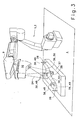
- Figure 1 shows a mounting and manufacturing robot 1, below briefly called working robot 1, executed manipulator 2, the bottom side is firmly anchored in the ground 4 via a base 3.
- the working robot 1 are in a conventional manner, the tool carrier 5 forming segments 6 - 9 associated with a variety of horizontal and vertical Swivel axes 10 - 13 are movable.
- the illustrated embodiment takes the outer segment 9 of the working robot 1 a like a structure designed holding device 14, the bottom one of a Guide rail 15 and this guide rail 15 encompassing Guide carriage 16 formed linear guide system 17.
- the guide slide 16 of the linear guide system 17 is in its lower side Area a likewise tragwerkartig executed holding device 18th associated with the guide carriage 17 in the simplest case by not shown screwings is firmly connected.
- the further holding device 18 are facing away from the guide carriage 16 in their Formed Adaptionsockel 19, in accordance with the invention record a contour measuring device 20 rotationally fixed.
- the contour measuring device 20 comprises a laser beam source 21 in a manner known per se, whose laser beam 22 is deflected by a mirror lens system 23 and is split, wherein the sensing surface 24 according to the invention results.
- Such a method is also laser light section method and the sensing surface 24 generating sensor unit 25 and laser light section sensor 26 called. It is within the scope of the invention that here Other optical methods may be used, either also generate a planar or a point-shaped Sensierfeld.
- the contour measuring device in its the sensor unit 25 facing away Area a protected by a viewing window 27 lens 28th on, which in more detail to be described manner the cutting area 29 detect between Sensier Chemistry 24 and measuring range 30 and to a Can forward detector 31, wherein the detector 31, the cutting surface 29th maps and an electronic signal unit 32 as output signals 33 for further processing.
- the sensing surface 24 passes over the contour measuring device a measuring range 30, wherein the size of the measuring range the degree of fanning of the laser beam 22 in the mirror lens system 23 and the travel 34 of the guide carriage 16 of the Linear guide system 17 depends.
- the measuring area 30 thus formed according to the invention at least one component 35 is arranged, which via has at least one measuring object 36 lying in the measuring area 30, which of the sensing surface 24 of the linearly movable contour measuring device 20 is covered.
- Component 35 is in the simplest case in a manner not shown in a component carrier 37 screwed or otherwise, suitably in the component carrier 37 be fixed.
- the reference feature according to the invention 38 wherein the reference feature 38 of Figure 1 as a pyramid-shaped geometric body 39 is formed, the punctiform expiring header the reference feature 38 forming reference point 40 represents.
- the pyramidal geometric Body 39 also screwed into the component carrier 37, wherein the location of this body 39 is chosen so that the reference feature 38 is associated with at least one measurement object 36 of the component 35 and also within the swept by the Sensier Chemistry 24 measuring range 30 lies.
- the contour measuring device 20 receiving holding device 18 on top of a pivot axis 44th receives from one with the front segment 9 of the working robot 1 connected flange bearing 45 is added.
- a drive may be provided which the contour measuring device 20 according to arrow 46 about the pivot axis 44th pivots leads.
- the linear guide system 17 omitted according to FIG.
- the contour measuring device 20th rigidly arranged on the working robot 1 and the component carrier 37 with the fixed on it component 35 and the reference features 38 linear according to the direction of arrow 47 to move in such a way that at least the at least one measurement object 36 of the component 35 and the measurement object 36 associated reference feature 38 through the sensing surface 24 of the contour measuring device 20 is performed.
- the change in position of Sensier Chemistry 24th sensory detected and transmitted to the accounting unit 42 In known per se and therefore not shown, this can Determining the change in position by means of a displacement measuring system 52 become.
- the respective holding device 18 are linear or circular trained scales 53 assigned, whose not shown Markings arranged by the moving holding devices 18 Position sensors 54 are tapped.
- the scales 53 in the Usually made of glass, with the markings usually engraved or are milled.
Landscapes
- Engineering & Computer Science (AREA)
- Physics & Mathematics (AREA)
- Computer Vision & Pattern Recognition (AREA)
- General Physics & Mathematics (AREA)
- Electromagnetism (AREA)
- Multimedia (AREA)
- Signal Processing (AREA)
- Length Measuring Devices By Optical Means (AREA)
- Length Measuring Devices With Unspecified Measuring Means (AREA)
- Manipulator (AREA)
Applications Claiming Priority (2)
| Application Number | Priority Date | Filing Date | Title |
|---|---|---|---|
| DE10341042A DE10341042A1 (de) | 2003-09-03 | 2003-09-03 | Vorrichtung und Verfahren zur Vermessung von Bauteilen |
| DE10341042 | 2003-09-03 |
Publications (2)
| Publication Number | Publication Date |
|---|---|
| EP1512940A2 true EP1512940A2 (fr) | 2005-03-09 |
| EP1512940A3 EP1512940A3 (fr) | 2009-11-18 |
Family
ID=34129666
Family Applications (1)
| Application Number | Title | Priority Date | Filing Date |
|---|---|---|---|
| EP04019452A Ceased EP1512940A3 (fr) | 2003-09-03 | 2004-08-17 | Dispositif et procédé pour mesurer des composants |
Country Status (3)
| Country | Link |
|---|---|
| US (2) | US20050046871A1 (fr) |
| EP (1) | EP1512940A3 (fr) |
| DE (1) | DE10341042A1 (fr) |
Cited By (2)
| Publication number | Priority date | Publication date | Assignee | Title |
|---|---|---|---|---|
| EP1593930A1 (fr) * | 2004-05-06 | 2005-11-09 | CLAAS Fertigungstechnik GmbH | Dispositif et procédé pour mesurer des objets |
| DE102006005874B4 (de) * | 2005-05-11 | 2012-02-16 | Hgv Vosseler Gmbh & Co. Kg | Verfahren zum berührungsfreien Vermessen |
Families Citing this family (7)
| Publication number | Priority date | Publication date | Assignee | Title |
|---|---|---|---|---|
| DE102004017172A1 (de) * | 2004-04-02 | 2005-10-20 | Jan Bernd Lugtenburg | Verfahren und Vorrichtung zur Vermessung eines Messobjekts |
| US7289216B2 (en) * | 2004-07-19 | 2007-10-30 | Compagnie Plastic Omnium | Station for inspecting the painting of motor vehicle parts |
| DE102005042902A1 (de) * | 2004-12-16 | 2007-03-22 | Benteler Automobiltechnik Gmbh | Vorrichtung zum Vermessen von Bauteilen und Auswerteeinheit |
| DE102006013584B4 (de) | 2006-03-22 | 2014-07-10 | Benteler Automobiltechnik Gmbh | Vorrichtung zum Vermessen von Bauteilen |
| DE102006016677A1 (de) * | 2006-04-08 | 2007-10-11 | Fraunhofer-Gesellschaft zur Förderung der angewandten Forschung e.V. | Verfahren und Vorrichtung zur Vermessung geometrischer Merkmale von Objekten mit einem robotergeführten Lasersensor |
| DE102010021317A1 (de) * | 2010-05-22 | 2011-12-08 | Bernhard Schäfer | Handgerät zum Erfassen von Maßen |
| US9488469B1 (en) * | 2013-04-22 | 2016-11-08 | Cognex Corporation | System and method for high-accuracy measurement of object surface displacement using a laser displacement sensor |
Citations (6)
| Publication number | Priority date | Publication date | Assignee | Title |
|---|---|---|---|---|
| US4498778A (en) | 1981-03-30 | 1985-02-12 | Technical Arts Corporation | High speed scanning method and apparatus |
| US6078846A (en) | 1996-02-06 | 2000-06-20 | Perceptron, Inc. | Calibration and compensation of robot-based gauging system |
| FR2792720A1 (fr) | 1999-04-23 | 2000-10-27 | Process Conception Ing Sa | Procede et dispositif de controle de silhouette de vehicule automobile |
| WO2001007866A1 (fr) | 1999-07-13 | 2001-02-01 | Metronor Asa | Systeme de balayage de la geometrie d'objets de dimensions importantes |
| EP1302285A2 (fr) | 2001-09-06 | 2003-04-16 | Deutsches Zentrum für Luft- und Raumfahrt e.V. | Procédé de calibrage d'un bras de robot |
| US6615112B1 (en) | 1999-06-26 | 2003-09-02 | Kuka Schweissanlagen Gmbh | Method and device for calibrating robot measuring stations, manipulators and associated optical measuring devices |
Family Cites Families (6)
| Publication number | Priority date | Publication date | Assignee | Title |
|---|---|---|---|---|
| US4967370A (en) * | 1988-10-21 | 1990-10-30 | Robotic Vision Systems, Inc. | Robot and sensor error determination system |
| FR2642833B1 (fr) * | 1989-02-06 | 1991-05-17 | Vision 3D | Procede d'etalonnage d'un systeme d'acquisition tridimensionnelle de forme et systeme d'acquisition pour la mise en oeuvre dudit procede |
| DE19634254B4 (de) * | 1995-09-04 | 2009-06-10 | Volkswagen Ag | Optisch-numerisches Verfahren zur Ermittlung der gesamten Oberfläche eines dreidimensionalen Objektes |
| US6152662A (en) * | 1997-07-31 | 2000-11-28 | Machine Magic, Llc | Key duplication apparatus and method |
| DE19931676C2 (de) * | 1999-07-08 | 2002-07-11 | Kuka Schweissanlagen Gmbh | Verfahren zum Vermessen von Werkstücken und Bearbeitungsstation |
| DE10017463B4 (de) * | 2000-04-07 | 2006-07-20 | Metronom Ag | Verfahren und Vorrichtung zum Vermessen von Objekten |
-
2003
- 2003-09-03 DE DE10341042A patent/DE10341042A1/de not_active Withdrawn
-
2004
- 2004-08-17 EP EP04019452A patent/EP1512940A3/fr not_active Ceased
- 2004-09-01 US US10/931,598 patent/US20050046871A1/en not_active Abandoned
-
2006
- 2006-03-21 US US11/385,116 patent/US7199881B2/en not_active Expired - Fee Related
Patent Citations (6)
| Publication number | Priority date | Publication date | Assignee | Title |
|---|---|---|---|---|
| US4498778A (en) | 1981-03-30 | 1985-02-12 | Technical Arts Corporation | High speed scanning method and apparatus |
| US6078846A (en) | 1996-02-06 | 2000-06-20 | Perceptron, Inc. | Calibration and compensation of robot-based gauging system |
| FR2792720A1 (fr) | 1999-04-23 | 2000-10-27 | Process Conception Ing Sa | Procede et dispositif de controle de silhouette de vehicule automobile |
| US6615112B1 (en) | 1999-06-26 | 2003-09-02 | Kuka Schweissanlagen Gmbh | Method and device for calibrating robot measuring stations, manipulators and associated optical measuring devices |
| WO2001007866A1 (fr) | 1999-07-13 | 2001-02-01 | Metronor Asa | Systeme de balayage de la geometrie d'objets de dimensions importantes |
| EP1302285A2 (fr) | 2001-09-06 | 2003-04-16 | Deutsches Zentrum für Luft- und Raumfahrt e.V. | Procédé de calibrage d'un bras de robot |
Cited By (3)
| Publication number | Priority date | Publication date | Assignee | Title |
|---|---|---|---|---|
| EP1593930A1 (fr) * | 2004-05-06 | 2005-11-09 | CLAAS Fertigungstechnik GmbH | Dispositif et procédé pour mesurer des objets |
| DE102006005874B4 (de) * | 2005-05-11 | 2012-02-16 | Hgv Vosseler Gmbh & Co. Kg | Verfahren zum berührungsfreien Vermessen |
| DE102006005874C5 (de) * | 2005-05-11 | 2017-05-18 | Carl Zeiss Automated Inspection GmbH | Verfahren zum berührungsfreien Vermessen |
Also Published As
| Publication number | Publication date |
|---|---|
| US20060158663A1 (en) | 2006-07-20 |
| US20050046871A1 (en) | 2005-03-03 |
| EP1512940A3 (fr) | 2009-11-18 |
| US7199881B2 (en) | 2007-04-03 |
| DE10341042A1 (de) | 2005-03-31 |
Similar Documents
| Publication | Publication Date | Title |
|---|---|---|
| EP1593930B1 (fr) | Dispositif et procédé pour mesurer des objets | |
| EP0881461B1 (fr) | Système pour la détection metrologique spatiale à 3D des points d'une surface | |
| DE102016118617B4 (de) | Messsystem | |
| DE10112653B4 (de) | System zur Positionspeilung | |
| EP1347266B1 (fr) | Dispositif de mesure d' un objet | |
| DE102007004934B4 (de) | Prüfverfahren für positionierende Maschinen | |
| WO2007107324A1 (fr) | Corps d'essai et procede de calibrage d'un appareil de mesure de coordonnees | |
| DE112006001423B4 (de) | Koordinatenmessgerät sowie Verfahren zum Messen eines Objektes mit einem Koordinatenmessgerät | |
| DE102004007830B4 (de) | Verfahren zur Lokalisierung von Fehlstellen und Markiersystem | |
| EP1512940A2 (fr) | Dispositif et procédé pour mesurer des composants | |
| DE102017003641B4 (de) | Verfahren zur Messung von Koordinaten oder Eigenschaften einer Werkstückoberfläche | |
| WO2004065904A1 (fr) | Procede de mesure optique et machine de mesure de precision pour la determination d'ecarts par rapport a une forme ideale de surfaces polies par des moyens techniques | |
| DE102018114809B4 (de) | Messsystem, insbesondere Koordinatenmessgerät | |
| DE10319711B4 (de) | Verfahren zur hochgenauen dimensionalen Messung an Messobjekten | |
| DE102004022314A1 (de) | Koordinatenmessgerät sowie Verfahren zum Messen von Strukturen mittels eines Koordinatenmessgerätes | |
| DE102020111509B4 (de) | Koordinatenmessgerät sowie Verfahren zum Messen von Koordinaten eines Werkstücks | |
| EP3069101B1 (fr) | Procédé de mesure d'objets à mesurer | |
| DE102010064652B3 (de) | Verfahren zur Genauigkeitssteigerung einer positionierenden Maschine und positionierende Maschine | |
| DE19926439C1 (de) | Verfahren zur Bestimmung eines Koordinatensytems für Messpunktskoordinaten an einer Vorrichtung zur berührungslosen dreidimensionalen Vermessung von Körpern | |
| EP4339556B1 (fr) | Procédé et dispositif de détermination de propriétés de surface d'une pièce | |
| DE102016013550B3 (de) | Profilmesssystem für eine Rauheits- und Konturmessung an einer Oberfläche eines Werkstücks | |
| DE102020124704B4 (de) | Vorrichtung und Verfahren zur Erfassung einer räumlichen Position eines Körpers | |
| DE10328640B4 (de) | Messanordnung zur Prüfung der Arbeitsgenauigkeit einer Maschine | |
| DE10349946B4 (de) | Anordnung zur Messung von Oberflächeneigenschaften | |
| DE102008022230A1 (de) | Vorrichtung zur referenzbezogenen Messung von Form und Struktur |
Legal Events
| Date | Code | Title | Description |
|---|---|---|---|
| PUAI | Public reference made under article 153(3) epc to a published international application that has entered the european phase |
Free format text: ORIGINAL CODE: 0009012 |
|
| AK | Designated contracting states |
Kind code of ref document: A2 Designated state(s): AT BE BG CH CY CZ DE DK EE ES FI FR GB GR HU IE IT LI LU MC NL PL PT RO SE SI SK TR |
|
| AX | Request for extension of the european patent |
Extension state: AL HR LT LV MK |
|
| RIN1 | Information on inventor provided before grant (corrected) |
Inventor name: KRAUHAUSEN, MICHAEL Inventor name: ECKSTEIN, JUERGEN Inventor name: HERRMANN, GUENTER Inventor name: MARTINSCHLEDDE, LUDGER |
|
| PUAL | Search report despatched |
Free format text: ORIGINAL CODE: 0009013 |
|
| AK | Designated contracting states |
Kind code of ref document: A3 Designated state(s): AT BE BG CH CY CZ DE DK EE ES FI FR GB GR HU IE IT LI LU MC NL PL PT RO SE SI SK TR |
|
| AX | Request for extension of the european patent |
Extension state: AL HR LT LV MK |
|
| 17P | Request for examination filed |
Effective date: 20100518 |
|
| AKX | Designation fees paid |
Designated state(s): AT BE BG CH CY CZ DE DK EE ES FI FR GB GR HU IE IT LI LU MC NL PL PT RO SE SI SK TR |
|
| 17Q | First examination report despatched |
Effective date: 20100629 |
|
| RAP1 | Party data changed (applicant data changed or rights of an application transferred) |
Owner name: MBB FERTIGUNGSTECHNIK GMBH |
|
| APBK | Appeal reference recorded |
Free format text: ORIGINAL CODE: EPIDOSNREFNE |
|
| APBN | Date of receipt of notice of appeal recorded |
Free format text: ORIGINAL CODE: EPIDOSNNOA2E |
|
| APAF | Appeal reference modified |
Free format text: ORIGINAL CODE: EPIDOSCREFNE |
|
| APBT | Appeal procedure closed |
Free format text: ORIGINAL CODE: EPIDOSNNOA9E |
|
| STAA | Information on the status of an ep patent application or granted ep patent |
Free format text: STATUS: THE APPLICATION HAS BEEN REFUSED |
|
| 18R | Application refused |
Effective date: 20140813 |