EP1512983A1 - NMR-Kryokopf mit getrennten Wärmetauschern für die Kühlung der Detektions-Spulen und der Sende bzw. Entkopplungs-Spulen - Google Patents
NMR-Kryokopf mit getrennten Wärmetauschern für die Kühlung der Detektions-Spulen und der Sende bzw. Entkopplungs-Spulen Download PDFInfo
- Publication number
- EP1512983A1 EP1512983A1 EP04020216A EP04020216A EP1512983A1 EP 1512983 A1 EP1512983 A1 EP 1512983A1 EP 04020216 A EP04020216 A EP 04020216A EP 04020216 A EP04020216 A EP 04020216A EP 1512983 A1 EP1512983 A1 EP 1512983A1
- Authority
- EP
- European Patent Office
- Prior art keywords
- heat exchanger
- decoupling
- temperature
- coil
- heat exchangers
- Prior art date
- Legal status (The legal status is an assumption and is not a legal conclusion. Google has not performed a legal analysis and makes no representation as to the accuracy of the status listed.)
- Granted
Links
- 238000001514 detection method Methods 0.000 title claims abstract description 103
- 238000001816 cooling Methods 0.000 title claims abstract description 89
- 239000001307 helium Substances 0.000 claims abstract description 11
- 229910052734 helium Inorganic materials 0.000 claims abstract description 11
- SWQJXJOGLNCZEY-UHFFFAOYSA-N helium atom Chemical compound [He] SWQJXJOGLNCZEY-UHFFFAOYSA-N 0.000 claims abstract description 11
- 238000005481 NMR spectroscopy Methods 0.000 claims abstract description 10
- 239000012530 fluid Substances 0.000 claims description 23
- 238000005259 measurement Methods 0.000 claims description 2
- 239000007789 gas Substances 0.000 description 27
- 238000010438 heat treatment Methods 0.000 description 24
- 239000000523 sample Substances 0.000 description 19
- 238000004458 analytical method Methods 0.000 description 13
- 230000008901 benefit Effects 0.000 description 12
- 238000010586 diagram Methods 0.000 description 10
- 238000009529 body temperature measurement Methods 0.000 description 9
- 239000002826 coolant Substances 0.000 description 9
- 239000012071 phase Substances 0.000 description 9
- 210000002023 somite Anatomy 0.000 description 8
- 230000005540 biological transmission Effects 0.000 description 7
- 238000012546 transfer Methods 0.000 description 7
- 230000033228 biological regulation Effects 0.000 description 5
- 230000008859 change Effects 0.000 description 4
- 238000013461 design Methods 0.000 description 4
- 238000005516 engineering process Methods 0.000 description 4
- 238000002474 experimental method Methods 0.000 description 4
- 238000010792 warming Methods 0.000 description 4
- 230000009286 beneficial effect Effects 0.000 description 3
- 230000000694 effects Effects 0.000 description 3
- 230000006872 improvement Effects 0.000 description 3
- 239000007788 liquid Substances 0.000 description 3
- 238000000034 method Methods 0.000 description 3
- 230000001105 regulatory effect Effects 0.000 description 3
- 230000002441 reversible effect Effects 0.000 description 3
- 238000001228 spectrum Methods 0.000 description 3
- 230000002123 temporal effect Effects 0.000 description 3
- IJGRMHOSHXDMSA-UHFFFAOYSA-N Atomic nitrogen Chemical compound N#N IJGRMHOSHXDMSA-UHFFFAOYSA-N 0.000 description 2
- 239000002131 composite material Substances 0.000 description 2
- 230000003247 decreasing effect Effects 0.000 description 2
- 230000001419 dependent effect Effects 0.000 description 2
- 238000011156 evaluation Methods 0.000 description 2
- 230000002349 favourable effect Effects 0.000 description 2
- 238000009413 insulation Methods 0.000 description 2
- 239000007791 liquid phase Substances 0.000 description 2
- 230000007774 longterm Effects 0.000 description 2
- 238000004445 quantitative analysis Methods 0.000 description 2
- 230000005855 radiation Effects 0.000 description 2
- 230000002829 reductive effect Effects 0.000 description 2
- 230000035945 sensitivity Effects 0.000 description 2
- 238000000926 separation method Methods 0.000 description 2
- 230000036962 time dependent Effects 0.000 description 2
- 241000269627 Amphiuma means Species 0.000 description 1
- OKTJSMMVPCPJKN-UHFFFAOYSA-N Carbon Chemical compound [C] OKTJSMMVPCPJKN-UHFFFAOYSA-N 0.000 description 1
- YZCKVEUIGOORGS-OUBTZVSYSA-N Deuterium Chemical compound [2H] YZCKVEUIGOORGS-OUBTZVSYSA-N 0.000 description 1
- 240000003517 Elaeocarpus dentatus Species 0.000 description 1
- 238000010521 absorption reaction Methods 0.000 description 1
- 230000004888 barrier function Effects 0.000 description 1
- 229910052799 carbon Inorganic materials 0.000 description 1
- 230000015556 catabolic process Effects 0.000 description 1
- 238000005352 clarification Methods 0.000 description 1
- 238000010276 construction Methods 0.000 description 1
- 230000001276 controlling effect Effects 0.000 description 1
- 230000008878 coupling Effects 0.000 description 1
- 238000010168 coupling process Methods 0.000 description 1
- 238000005859 coupling reaction Methods 0.000 description 1
- 230000007423 decrease Effects 0.000 description 1
- 238000006731 degradation reaction Methods 0.000 description 1
- 230000006866 deterioration Effects 0.000 description 1
- 229910052805 deuterium Inorganic materials 0.000 description 1
- 229940079593 drug Drugs 0.000 description 1
- 239000003814 drug Substances 0.000 description 1
- 238000001704 evaporation Methods 0.000 description 1
- 230000008020 evaporation Effects 0.000 description 1
- 230000004907 flux Effects 0.000 description 1
- 230000005415 magnetization Effects 0.000 description 1
- 239000000463 material Substances 0.000 description 1
- 230000003340 mental effect Effects 0.000 description 1
- 229910052751 metal Inorganic materials 0.000 description 1
- 239000002184 metal Substances 0.000 description 1
- 150000002739 metals Chemical class 0.000 description 1
- 239000000203 mixture Substances 0.000 description 1
- 229910052757 nitrogen Inorganic materials 0.000 description 1
- 238000001208 nuclear magnetic resonance pulse sequence Methods 0.000 description 1
- 230000009467 reduction Effects 0.000 description 1
- 230000003595 spectral effect Effects 0.000 description 1
- 230000006641 stabilisation Effects 0.000 description 1
- 238000011105 stabilization Methods 0.000 description 1
- 230000003068 static effect Effects 0.000 description 1
- 238000002076 thermal analysis method Methods 0.000 description 1
Images


Classifications
-
- G—PHYSICS
- G01—MEASURING; TESTING
- G01R—MEASURING ELECTRIC VARIABLES; MEASURING MAGNETIC VARIABLES
- G01R33/00—Arrangements or instruments for measuring magnetic variables
- G01R33/20—Arrangements or instruments for measuring magnetic variables involving magnetic resonance
- G01R33/28—Details of apparatus provided for in groups G01R33/44 - G01R33/64
- G01R33/32—Excitation or detection systems, e.g. using radio frequency signals
- G01R33/34—Constructional details, e.g. resonators, specially adapted to MR
- G01R33/34046—Volume type coils, e.g. bird-cage coils; Quadrature bird-cage coils; Circularly polarised coils
- G01R33/34076—Birdcage coils
-
- G—PHYSICS
- G01—MEASURING; TESTING
- G01R—MEASURING ELECTRIC VARIABLES; MEASURING MAGNETIC VARIABLES
- G01R33/00—Arrangements or instruments for measuring magnetic variables
- G01R33/20—Arrangements or instruments for measuring magnetic variables involving magnetic resonance
- G01R33/28—Details of apparatus provided for in groups G01R33/44 - G01R33/64
- G01R33/32—Excitation or detection systems, e.g. using radio frequency signals
- G01R33/34—Constructional details, e.g. resonators, specially adapted to MR
- G01R33/34015—Temperature-controlled RF coils
- G01R33/34023—Superconducting RF coils
-
- G—PHYSICS
- G01—MEASURING; TESTING
- G01R—MEASURING ELECTRIC VARIABLES; MEASURING MAGNETIC VARIABLES
- G01R33/00—Arrangements or instruments for measuring magnetic variables
- G01R33/20—Arrangements or instruments for measuring magnetic variables involving magnetic resonance
- G01R33/28—Details of apparatus provided for in groups G01R33/44 - G01R33/64
- G01R33/32—Excitation or detection systems, e.g. using radio frequency signals
- G01R33/34—Constructional details, e.g. resonators, specially adapted to MR
- G01R33/34092—RF coils specially adapted for NMR spectrometers
Definitions
- NMR nuclear magnetic resonance
- HF high frequency
- Such a cryopot is known from US 5,889,456.
- An arrangement for measuring by means of nuclear magnetic resonance is located in the strong stationary magnetic field of a typically superconducting Magnet a so-called probe head. These are the sample to be measured introduced.
- S / N signal to noise ratio
- the head contains one Detection channel (e.g., 1 H (protons)), and one or more so-called Decoupling channels (e.g., 13C and 15N (isotopes of carbon and Nitrogen)).
- Detection channel e.g., 1 H (protons)
- Decoupling channels e.g., 13C and 15N (isotopes of carbon and Nitrogen)
- it usually contains a lock channel for Stabilization of the magnetic field that uses deuterium (2H).
- 2H deuterium
- Such a Head is called a Triple Resonance Inverse Head (TXI).
- the sensitivity is on the Detection channel (1 H) is maximized.
- the Decoupling cores 13C and 15N only for decoupling and for Magnetization transfer used.
- Such a head typically has two HF coils. An inner, on which the detection channel is arranged, and a second, surrounding outer, on which the X channels (13C and 15N) are arranged.
- the lock core can be either on the inner or the outer coil to be switched with.
- the sensitivity (ie, the signal) is optimized by placing the detection coil as close to the sample as possible, ie, around the inside of the sample.
- a second point is additionally optimized by cooling the RF coils to low temperatures, typically ⁇ 25K.
- the preamplifier is typically also cooled, so that its noise contribution is not disproportionately large in comparison to the then very low thermal noise of the receiving coil. This can z. B. be operated at 77K or at a lower temperature.
- the cold is the coil system typically by means of a cold, gaseous He-circuit supplied (or the heat dissipated).
- a cold, gaseous He-circuit supplied or the heat dissipated.
- An inexpensive version in practice is the use of a Gifford McMahon Cryocoolers that cools this cold he-cycle. Usually Such coolers run in two stages to the required low temperatures to reach.
- the preamplifier is also cooled. It is also advantageous and corresponds to the state the technology that the preamplifier is built into the cryopot to S / N Losses by routing signal lines between the RF coil and to minimize the preamplifier. The preamplifier will change according to the state of Technology also cooled by the cryocooler.
- 77K is used in the prior art by means of the warmer circuit 9 for cooling preamplifiers and structural elements in the cryopot, which helps to save the required cooling capacity for the cold circuit. This is particularly possible because at the warmer stage 7 of the coldhead 6 significantly more cooling power is obtained than at the colder stage 8.
- the cold circuit 10 [ ⁇ 25K] is then used to the RF coil assembly with the lowest possible thermal power and temperature losses cool.
- the sample 2 to be measured is located in one of the high-frequency fields permeable so-called central tube 22, which passes through the cryochip goes. This tube as well as the sample 2 are approximately on Room temperature.
- the detection coil 11 as well as the decoupling coil 12 be heated to working temperature ( ⁇ 25K) by means of the heat exchanger 13 cooled.
- vacuum 3 Inside the cryo head is vacuum 3, which has the necessary Thermal insulation of the cold parts against the central tube and thus the Assured sample as well as against the outer surfaces of the cryopot.
- the preamplifier 4 is also cooled.
- the cooling of the coil heat exchanger 13 is done by means of the cooling loop 10 ("cold Cooling loop "), and the preamplifier cooling to typically 77K by means of the cooling loop 9 ("warm cooling loop”).
- the cold is generated in the cooling system 5. This is with the cryopot by means of also evacuated transfer line 40 connected.
- the cold in the cooling system 5 is produced in Coldhead 6. This typically has two stages, the first stage 7 with a temperature of about 40-77K, and the second stage 8 with a temperature ⁇ 25K.
- the cooling medium, here He-gas is accompanied by a Room temperature operated compressor (not shown) driven, the is connected to the cooling system by means of the terminals 41.
- the first at Room temperature He gas is by means of the counterflow heat exchanger Pre-cooled 32, then with the stage heat exchanger 38 of first coldhead stage 7 further cooled. Then it goes through the second Counter flow heat exchanger 33, where it is further pre - cooled, to the stage heat exchanger 39 of the second coldhead stage 8.
- the throttle valve 34 forms a bypass for any necessary Regulation of the cooling capacity of the cooling loop 9.
- both the RF coils to cool as well as the one or the preamp.
- the details of the cooling of Preamplifier electronics are not for the present invention of primary relevance and will not be discussed further here.
- the detection coil should be as possible during the whole experiment a constant temperature work, so on the one hand no Noise changes or increases in operation result. On the other hand it is also possible that the self-resonance of the coil to some extent is temperature dependent. Thus, in a pulsed operation, the Decoupling frequency changes of the coil result, causing disturbing Phase modulation artifacts in the spectra obtained.
- the detection coil 11 is thermally from same heat exchanger 13 as the decoupling coil 12 cooled.
- the temperature of the heat exchanger 13 with an active control consisting of a temperature sensor 36 and a heater 37 by means of a Control system (not shown) held constant (Fig. 4).
- control may indicate a constant temperature value
- the true temperature history of the RF coils not so easy. This is shown in Fig. 5 for an arrangement according to the prior art shown.
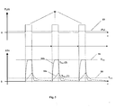
- the time profile of the decoupling power P D (t) is shown as a function of time.
- the lower illustration shows the temperature increase of both RF coils ⁇ T c (compared to the case without decoupling).
- the average power ⁇ P D ⁇ results in a temperature increase of the mean temperature. This is shown with T Ave.
- the coil assembly heats up and the Heat exchanger 13 very strong, since during this time a very high performance which far exceeds the average (CW) power (factor 1 / D).
- T Dyn (2) the temperature rises rapidly. This is represented by T Dyn (2).
- the temperature already reaches the maximum asymptotic temperature T Asy within the decoupling time and stabilizes there more or less. This value is significantly above the mean temperature T Ave (due to factor 1 / D).
- the thermal conditions the detection coil in contrast to the beautiful and constant middle Regulation temperature, which simulates the control system, far from ideal.
- the actual temperature of the detection coil can be very high are significantly above the supposed and therefore the actual possible Reduce performance and spectral quality.
- the object of the present invention is to overcome the above disadvantages of the prior art to avoid the technique, in particular a minimum and constant absolute Temperature at the receiving coil to ensure.
- a cryopot of the type presented at the outset achieved in that at least two heat exchangers are provided, wherein at least one first heat exchanger, the RF coil or the resonator of the at least one detection channel and at least one other Heat exchanger, the RF coil or the resonator of the at least one Transmitting or decoupling channels cool, and wherein the at least one first Heat exchanger separated from the at least one further heat exchanger is.
- the above, subtle but very serious disadvantages can be corrected according to the invention, when the cooling of the detection and Decoupling coils is decoupled more or less completely.
- the Cooling decoupling takes place according to the invention by at least two spatially separated heat exchangers, namely the at least a first heat exchanger and the at least one further (second) Heat exchanger.
- the available total cooling capacity is targeted distributed to the RF coils or resonators of the individual channels.
- a deeper and better constant temperature to be set as on the one or more RF coils or resonators of the at least one transmitting or Decoupling channels, where a high pulsed RF power is generated.
- Temperature fluctuations in the area of the transmitting or decoupling coils no longer hit the temperature of the receiver coil. Thereby the quality of the detected NMR signals is significantly improved.
- the probe head is replaced with one according to the invention with two or more equipped separate heat exchangers, the thermally possible from each other are decoupled. While the one heat exchanger, the detection coil cools, the decoupling coil with a separate heat exchanger cooled.
- the concrete execution are different, especially the listed below variants possible.
- An embodiment of the cryochip according to the invention is preferred in which the one or more heat exchangers of the at least one detection channel a separate cooling loop of the fluid can be cooled by a Cooling loop of the one or more heat exchangers of at least a transmission or decoupling channel is separated. First and more Heat exchangers are then completely decoupled with respect to the fluid and can be operated with respectively adapted cooling capacity.
- Separate cooling loops are characterized in that they at the probe head (Cryo head) each have their own supply and discharge lines for the fluid (coolant) have. This allows each separate absolute temperatures in the individual cooling loops adjusted via the respectively supplied fluid become.
- both cooling loops also separate, completely provided independent coolant circuits outside the probe head be. It can even have two separate coolers (coldheads) for the two circuits are used. In most cases, however, one will used only coldhead, which cools both circuits. Preference is given however further, only one coolant circuit in the entire arrangement, however, the cooling of the coolant outside the probe head with several heat exchangers or cooling stages (Cooler) in different places the cooling circuit takes place, so that in individual sections of the cooling circuit different absolute temperatures are adjustable.
- the single ones Cooling loops of the probe head are then each in such Integrated sections of the cooling circuit.
- the one or more heat exchangers of the at least one detection channel and the one or more heat exchangers of the at least one transmitting or Decoupling channels with a common cooling loop of the fluid are coolable. This simplifies the construction of a cooling system. Prefers the fluid then passes through first or the heat exchanger of the at least one detection channel to get a powerful and fluctuation-free (as coming directly from the cooler) cooling performance too guarantee; Subsequently, the one or more heat exchangers of or the transmission / decoupling channels flows through the fluid.
- the at least one transmitting or decoupling channel can according to the invention be set up for the same or for another core like that at least one cooled detection channel.
- the Transmit / decoupling channel for 13C be set up
- the detection channel in another example of a system according to the invention are for Sending and receiving signals with respect to a core separate Coils / resonators provided.
- the latter systems are particularly in the Medicine beneficial.
- the two RF signals are then over separate RF cables guided.
- FIG. 1 Such an arrangement is shown in FIG .
- a coldhead is used for the cooling of both circuits in this embodiment for the sake of simplicity.
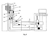
- the decoupling coil 12 is cooled by the "warm” circuit 9 while the detection coil 11 is cooled by the "cold” circuit 10.
- the detection coil 11 would have a temperature of ⁇ 25K, and the decoupling coil would be one of about 40-77K, depending on the specific circumstances of the coldhead used, as well as the structural design of the hardware.
- the division of the cooling capacity between the heat exchanger 15 and the preamplifier electronics can be adjusted if necessary with a bypass throttle valve 23.
- FIG. 7 shows a maximum configuration with up to 3 regulated temperatures.
- Detection coil 11 temperature sensor 16, heater 17, decoupling coil 12: temperature sensor 18, heater 19, preamplifier electronics: temperature sensor 20, heater 21.
- preamplifier electronics temperature sensor 20, heater 21.
- FIG. 6 or FIG. 7 has the great advantage that the thermal load of the decoupling coil 12 affects the cold circuit 10 and thus the detection coil 11 only very indirectly, in a way that vanishes in practice. This is facilitated by the fact that the two characteristic curves (temperature vs. heat load) of the two cryocooler stages 7 and 8 are typically largely decoupled.
- the second stage cooling capacity is often virtually independent of the first stage load, as can be seen from the characteristics of the coldhead.
- the first stage of the coldhead has an immense cooling capacity compared to the second stage (typically over 20W of the first stage 7 compared to 1-5W of the second stage 8).
- decoupling services are tolerated, which are extremely high compared to the prior art.
- the second advantage is that the detection coil and its cooling system without Any unnecessary heat load can be operated. Thus, the lowest possible temperatures of the detection coil achievable.
- the third advantage is that the temperature of the detection coil is very high in time is constant, because the pulsed power peaks are separated by the Cooling loop 9 and the large mass and thus high specific heat of the Coldheads 6 with its stages 7 and 8 and its heat exchangers 38, 32, 8, 33 almost completely filtered out.
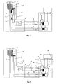
- the heat exchanger 15 of Decoupling coil 12 is not as in the first embodiment of the "warm” Circuit 9 cooled, but also directly from the "cold” cycle 10, as well the heat exchanger 14 of the detection coil 11 also. It is, however, whole essential that the two heat exchangers are not directly thermally to each other are coupled, but are in a row schmoort, wherein advantageously, the detection heat exchanger 14 first with the cold He is fed.
- FIG. 10 shows the equivalent circuit diagram of an arrangement according to the prior art, according to FIG. 2.
- the He is cooled with the heat exchanger 39.
- the outlet temperature T F of the gas flow exiting the cooling system 5 is now dependent on the total dissipated power in the cooling circuit.
- the Coldhead has a certain characteristic that describes how its temperature increases with increasing thermal load. To make this characteristic as simple as possible for the following considerations, it is assumed that the coldhead itself is at a given (intrinsic) temperature T CHintr . This is the temperature the second stage 8 of the coldhead would have if no RF powers were dissipated in the head.
- T F T CHintr + ⁇ P ⁇ * (R CH + R HXCH )
- ⁇ P ⁇ is the mean total of the cryopotal (over periods greater than or equal to the period 52 of the experiment) averaged over time Heat load.
- R CH is the equivalent thermal resistance of the coldhead (here its second stage 8), which indicates an increase in temperature as a function of dissipated power, thus describing its characteristic.
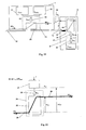
- a single heat exchanger is shown schematically.
- the whole heat exchanger 24 is shown in dashed lines. This is internally divided into a mental, 100% efficient heat exchanger 25, in series with a heat resistance 26 R HX , which describes the inefficiency of the heat exchanger (see Eq. 4 and Eq. 10 below).
- the heat exchanger 24 is thermally connected to the object 27 to be cooled. This gives off the heat load P.
- the object to be cooled 27 is cooled to the temperature T load .
- the gas flow has therefore warmed by the temperature dT flow .
- dT load tload - HX in as the temperature difference between the temperature T load of the load and the temperature HX in the incoming gas stream.
- This enthalpy balance is the basis for the cooling capacity in the heat exchanger.
- R He 1 / (Cp * dm / dt)
- R He is given by the mass flow according to Eq.
- R HX can match the efficiency E of the heat exchanger using Eqs. 4,6, and 8 are expressed as follows:
- R Hx R He (1 / E - 1)
- the Eq. 8 allows the relevant temperature differences in practical and express well-defined sizes.
- R He should not be greater than R CH , in order to keep the unnecessary heat transfer losses low.
- This equivalent resistance R He simply expresses how much the gaseous He must be heated in a heat exchanger to dissipate some power (Eq. 6). It is desirable to keep R He as low as possible.
- the value of R He can not be reduced by anything except increasing the mass flow. The increase in mass flow is technically difficult and soon reaches practical limits, since the efficiency of the cooling loop 10 drops rapidly due to increasing friction and pressure losses at high mass flows. Unfortunately, R He's limits are set lower, so the transmission losses in practice can not be reduced to some extent.
- the coldhead has a high thermal capacity, and thus this (ie its characteristic) is loaded only with the average power , and it can also be assumed in the first approximation that the temperature T F of the helium leaving the cooling system does not vary greatly during and between the individual pulses.
- the T F may be given by the mean power ⁇ P ⁇ , but then considered to be quite constant for a short time. Based on this, the further effects of the pulse power can then be investigated.
- T F T CHintr + ⁇ P ⁇ * R CH + P * (R He + R HX )
- T-name of the detection coil 100% 1.2K 6K 2.4 K 1.2K 6K 7.2 K 6K 7.2 K 50% 1.2K 12K 3.6 K 1.2K 12K 13.2K 12K 13.2 K 20% 1.2K 30K 7.2 K 1.2K 30K 31.2K 30K 31.2K
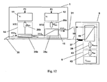
- FIG. 12 shows the equivalent circuit of an inventive arrangement according to FIG. 1 .
- HX1 (14) for the Detection coil
- HX2 (15) for the decoupling coil. It is for the Considerations below and for the optimal function that they are important be traversed in the order given.
- the detection coil 11 dissipate the power P1, the decoupling coil 12 the power P2.
- T1 T F + P1 * (R He + R HX1 )
- T2 T F + P1 * R He + P2 * (R He + R HX2 )
- T F is given by according to Eq. 1b:
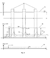
- Fig. 13 shows the temperatures of the detection and decoupling coil time-resolved.
- T c the common temperature of both coils was displayed
- T1 and T2 of the detection resp. the decoupling coil shown separately.
- ⁇ T1 is also referred to herein as ⁇ T Det and ⁇ T2 also as ⁇ T Dec for clarification of what the detection coil temperature and what the decoupling coil temperature is.
- the variants 1-3 can be any number of n Generalize heat exchangers.
- e.g. 3 Heat exchangers are used.
- the third heat exchanger may e.g. For a second decoupling channel can be used.
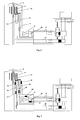
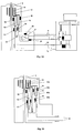
- a serial arrangement with the heat exchangers 14 for the detection coil and the Heat exchangers 15 and 15b for the decoupling coils 12 and 12b is shown in FIG Fig. 15 shown (here in full configuration with temperature measurement and control all levels, but this is not mandatory). This arrangement has the advantage that can be detected in addition to the coil 11 with the coil 12, without that this is due to a simultaneous decoupling on the coil 12b heated immediately.
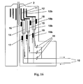
- FIG. 16 shows a parallel arrangement of three heat exchangers 14, as well as 15 and 15b (here too in the full configuration with temperature measurement and regulation of all stages, which is not mandatory).
- Each of the cooling streams can be individually adjusted by a throttle valve 35 as needed.
- none of the RF coils 11, 12, or 12b is directly heated by decoupling on one of the other coils.
- the heating only occurs through the mean value ⁇ P ⁇ , which results as the sum of all mean powers and the characteristic curve of the cooler.
- the heating of the just not thermally loaded coils then still results according to Eq. 1 b and is slow in time and minimal in value.
- the favorable properties achieved in the four embodiments were described with a fluid consisting of gaseous He and analyzed.
- Another gas for heat transport is also possible, such as also the use of a fluid with two phases.
- the cryo head entering fluid can be liquid or a mixture of liquid and gas phase be (in particular liquid / gaseous helium).
- the listed here Considerations can then be made with the additional energy balance of Heat of evaporation can be carried out.
- the Transmit / decouple coil referred to a different core than the Detection coil.
- the transmission and Reception function not only between two different cores, but also split within the same core into two RF coils / resonators be a channel with its RF coil for detection, the other for Send / decoupling.
- Such an arrangement has the advantage that in principle some or all of the transmit coils on e.g. the other one (second) Heat exchanger, and all detection coils on the first heat exchanger can be set.
- channel refers to each an RF coil or resonator, completely independent of which core this is provided or on which frequency this is operated.
Landscapes
- Physics & Mathematics (AREA)
- Condensed Matter Physics & Semiconductors (AREA)
- General Physics & Mathematics (AREA)
- Other Investigation Or Analysis Of Materials By Electrical Means (AREA)
- Investigating Or Analyzing Materials By The Use Of Magnetic Means (AREA)
- Investigating Or Analyzing Materials Using Thermal Means (AREA)
Abstract
Description
Bei den Kryoköpfen wird ein zweiter Punkt zusätzlich optimiert, indem die HF-Spulen auf tiefe Temperaturen gekühlt werden, typischerweise <25K. Zusätzlich wird typischerweise auch der Vorverstärker gekühlt, damit sein Rauschbeitrag nicht überproportional groß im Vergleich zum dann sehr geringen thermischen Rauschen der Empfangsspule wird. Dieser kann z. B. auf 77K oder auch auf einer tieferen Temperatur betrieben werden.
Die wärmere Temperatur [ca. 77K] wird nach dem Stand der Technik mittels des wärmeren Kreislaufs 9 zur Kühlung von Vorverstärkern sowie strukturellen Elementen im Kryokopf verwendet, was die erforderliche Kühlleistung für den kalten Kreislauf sparen hilft. Dies ist insbesondere möglich, da an der wärmeren Stufe 7 des Coldheads 6 wesentlich mehr Kühlleistung anfällt als an der kälteren Stufe 8. Der kalte Kreislauf 10 [<25K] wird dann verwendet, um die HF-Spulenanordnung mit möglichst geringen Wärmeleistungs- und Temperaturverlusten zu kühlen.
- Fig. 1
- Erfindungsgemäße Anordnung, zweite Variante, mit Serienschaltung der Wärmetauscher sowie mit Temperaturmessung und Heizungselement zwecks Temperaturregelung des ersten Wärmetauschers;
- Fig. 2
- Kryokopf mit Kühlsystem nach dem Stand der Technik (Übersicht) mit einem gemeinsamen Wärmetauscher für beide HF Spulen;
- Fig. 3
- Leistungs-Zeit-Diagramm für pulsweise Entkopplung nach dem Stand der Technik;
- Fig. 4
- System nach Stand der Technik, mit geregeltem Wärmetauscher für beide HF-Spulen;
- Fig. 5
- Leistungs-Zeit Diagramm und Temperaturdifferenz-Zeit-Diagramm für pulsweise Entkopplung beim System von Fig. 4 nach dem Stand der Technik - die gemeinsame Temperatur der HF-Spulen zeitaufgelöst, qualitative Darstellung;
- Fig. 6
- Erfindungsgemäße Anordnung, erste Variante, mit Kühlung der Entkopplungsspule über einen separaten Wärmetauscher;
- Fig. 7
- Erfindungsgemäße Anordnung, erste Variante, mit Temperaturmessung und Heizungselementen zwecks Temperaturregelung;
- Fig. 8
- Erfindungsgemäße Anordnung, zweite Variante, mit Serienschaltung der Wärmetauscher sowie Temperaturmessung und Heizungselementen zwecks Temperaturregelung aller Wärmetauscher;
- Fig. 9
- Leistungs-Zeit-Diagramm und Temperaturdifferenz-Zeit-Diagramm für pulsweise Entkopplung. Die Temperaturen der Detektions- und Entkopplungsspule sind separat aufgeführt. Qualitative Darstellung für das aufgeführte konkrete Beispiel mit einem Wärmetauscher nach dem Stand der Technik
- Fig. 10
- Thermisches Ersatzschaltbild einer Anordnung gemäß dem Stand der Technik;
- Fig. 11
- Prinzipielle Analyse des Ersatzschaltbildes und Effizienz eines einzelnen Wärmetauschers;
- Fig. 12
- Thermisches Ersatzschaltbild der zweiten erfindungsgemäßen Anordnung;
- Fig. 13
- Leistungs-Zeit-Diagramm und Temperaturdifferenz-Zeit-Diagramme für pulsweise Entkopplung. Die Temperaturen der Detektions- und Entkopplungsspule sind separat aufgeführt. Quantitative Darstellung für das aufgeführte konkrete Beispiel mit zwei Wärmetauschern einer erfindungsgemäßen Anordnung;
- Fig. 14
- Erfindungsgemäße Anordnung, dritte Variante, mit Parallelschaltung der Wärmetauscher. Temperaturmessung und Heizungselemente zwecks Temperaturregelung aller Wärmetauscher;
- Fig. 15
- Detail der Wärmetauscheranordnung für die vierte Ausführungsvariante, serielle Schaltung der Wärmetauscher;
- Fig. 16
- Detail der Wärmetauscheranordnung für die vierte Ausführungsvariante, parallele Schaltung der Wärmetauscher.
| Temperaturzunahme während Pulsen bei verschieden effizientem Wärmetauscher HX (bei den im Text angegebenen Bedingungen). | ||||||||
| Effizienz des Wärmetauschers HX | Coolererwärmung | Temperaturzunahme (zusätzlich zur Coolererwärmung) während Puls am HX | Mittlere Temperaturzunahme am HX (total), entspricht der mittleren Temperaturzunahme der Detektionsspule | Min. Temperaturzunahme am HX | Temperaturexkursion (Tmax-Tmin) der Entkopplungsspule | Max. Temperaturzunahme Entkopplungsspule (total) | Max. T- Exkursion der Detektionsspule | Max. T-Zuname der Detektionsspule |
| 100% | 1.2K | 6 K | 2.4 K | 1.2K | 6 K | 7.2 K | 6 K | 7.2 K |
| 50% | 1.2K | 12 K | 3.6 K | 1.2K | 12 K | 13.2K | 12 K | 13.2 K |
| 20% | 1.2K | 30 K | 7.2 K | 1.2K | 30 K | 31.2K | 30 K | 31.2K |
| Temperaturzunahme während Pulsen bei verschieden effizientem Wärmetauscher HX2 der Entkopplungsspule (bei den im Text angegebenen Bedingungen). | ||||||||
| Effizienz des HX2 | Coolererwärmung | Temperaturzunahme (zusätzl. zur Coolererwärmung) während Puls am HX2 | Mittlere Temperaturzunahme am HX2 (total) | Min. Temperaturzunahme am HX2 | Temperaturexkursion (Tmax-Tmin) der Entkopplungsspule | Max. Temperatuzunahme Entkopplungsspule (total) | Max. T-Exkursion der Detektionsspule | Max. T-Zunahme der Detektionsspule |
| 100% | 1.2K | 6 K | 2.4 K | 1.2K | 6 K | 7.2 K | 0 K | 1.2K |
| 50% | 1.2K | 12 K | 3.6 K | 1.2K | 12K | 13.2K | 0 K | 1.2K |
| 20% | 1.2K | 30 K | 7.2 K | 1.2K | 30 K | 31.2K | 0 K | 1.2K |
- 1
- Kryokopf
- 2
- Probe
- 3
- Vakuum
- 4
- Kalte Vorverstärker
- 5
- Kühlsystem
- 6
- Coldhead
- 7
- Erste Stufe Coldhead
- 8
- Zweite Stufe Coldhead
- 9
- "Warme" Kühlschlaufe
- 10
- "Kalte" Kühlschlaufe
- 11
- Detektionsspule
- 12
- Entkopplungsspule
- 12b
- Weitere Entkopplungsspule
- 13
- Wärmetauscher für die HF Spulen (gemeinsam für Detektions- und Entkopplungsspule)
- 14
- Wärmetauscher für Detektionsspule
- 15
- Wärmetauscher für Entkopplungsspule
- 16
- Temperatursensor Detektionsspule
- 17
- Heizer Detektionsspule
- 18
- Temperatursensor Entkopplungsspule
- 18b
- Temperatursensor von weiteren Entkopplungsspulen
- 19
- Heizer Entkopplungsspule
- 19b
- Heizer von weiteren Entkopplungsspulen
- 20
- Temperatursensor Vorverstärker
- 21
- Heizer Vorverstärker
- 22
- Zentralrohr
- 23
- Bypass Kühlung Elektronik
- 24
- Wärmetauscher allgemein
- 25
- Idealer Wärmetauscher allgemein
- 25b
- Idealer Wärmetauscher als Teil des Wärmetauschers 14
- 25c
- Idealer Wärmetauscher als Teil des Wärmetauschers 15
- 26
- Innerer Widerstand des Wärmetauschers allgemein
- 26b
- Innerer Widerstand des Wärmetauschers als Teil des Wärmetauschers 14
- 26b
- Innerer Widerstand des Wärmetauschers als Teil des Wärmetauschers 15
- 27
- Zu kühlendes Objekt allgemein
- 28
- Kühlmedium Eintritt in Wärmetauscher
- 29
- Kühlmedium Austritt aus Wärmetauscher
- 30
- Wärmeverlust (Temperaturzunahme im Vorwärtsfluss)
- 31
- Wärmeverlust (Temperaturzunahme im Rückwärtsfluss)
- 32
- Gegenstrom-Wärmetauscher im Kühler (Zwischen Raumtemperatur und erster Stufe)
- 33
- Gegenstrom-Wärmetauscher im Kühler (Zwischen erster und zweiter Stufe)
- 34.
- Bypass der Vorverstärkerkühlung
- 35
- Drosselventil zur Kontrolle des Kühlmittelflusses bei paralleler Anordnung der Wärmetauscher
- 36
- Temperatursensor für die HF Spulen
- 37
- Heizer für die HF Spulen
- 38
- Stufen-Wärmetauscher der ersten Coldheadstufe
- 39
- Stufen-Wärmetauscher der zweiten Coldheadstufe
- 40
- Transferline
- 41
- Anschlüsse für Zirkulationspumpe (Kompressor) bei Raumtemperatur
- 42
- Cooler Kennlinie, beschrieben durch äquivalenten Wärmewiderstand
- 43
- Innerer Widerstand des Cooler-Wärmetauschers
- 44
- Idealer Wärmetauscher am Cooler (2. Stufe)
- 45-49
- Nicht verwendet
- 50
- Entkopplungspuls
- 51
- Pause zwischen Entkopplungen
- 52
- Repetitionsperiode des Experiments
- 53
- Mittlere Entkopplungsleistung
- 54a
- Zeitlicher Temperaturverlauf am Wärmetauscher, bei langer thermischer Zeitkonstante
- 54b
- Zeitlicher Temperaturverlauf am Wärmetauscher, bei kurzer thermischer Zeitkonstante
- 55
- Mittlere Temperatur am Wärmetauscher
- 56
- Asymptotische Maximaltemperatur am Wärmetauscher
- 57
- Minimale Temperatur am Wärmetauscher
- 58
- Temperatur der Detektionsspule
- PD(t)
- Zeitabhängige Entkopplungsleistung
- {PD}
- Mittlere Entkopplungsleistung (Zeitmittel)
- TAve
- Mittlere Temperatur der .... Spulen (je nach Kontext)
- TAsy
- Asymptotische Temperatur, die während der Entkopplung erreicht werden kann
- C
- Spezifische Wärme der Spulenbaugruppe (Wärmetauscher 13 sowie die Spulen 11 und 12)
- TDyn(1)
- Dynamischer Temperaturverlauf bei hohem C
- TDyn(2)
- Dynamischer Temperaturverlauf bei niedrigem C
- T1
- Temperatur des Detektionswärmetauschers
- T2
- Temperatur des Entkopplungswärmetauschers
- TF
- Austrittstemperatur des kalten Kühlschlaufe 10 (Forward) aus dem Kühlsystem
- TCHintr
- Die intrinsische (minimale) Temperatur der zweiten Stufe des Coldheads, ohne Wärmebelastung aus der dissipierten HF Leistung
- HX
- Wärmetauscher im Kryokopf zur Kühlung beider HF Spulen
- HXin
- In den Wärmetauscher eintretendes He
- HXout
- Aus dem Wärmetauscher austretendes He
- P
- Wärmelast des abzukühlenden Objekts
- Tload
- Temperatur der Wärmelast (des abzukühlenden Objekts)
- dTflow
- Erwärmung des Gasstromes
- dTload
- Erwärmung der Wärmelast gegenüber der Temperatur des eintretendes Gasstromes
- dm/dt
- Massenfluss des Gases pro Zeiteinheit
- Cp
- Spezifische Wärme des Gases
- RHX
- Innerer Wärmewiderstand eines Wärmetauschers zur Beschreibung seiner Ineffizienz
- Tc.
- Temperatur der HF Spulen (beide Detektions- und Entkopplungsspule gemeinsam)
- Ppeak
- Peakleistung (Spitzenleistung) während Entkopplung
- Tcpeak
- Peak-Temperatur der Spulen
- HX1
- Wärmetauscher (14) der Detektionsspule (11)
- HX2
- Wärmetauscher (15) der Entkopplungsspule (12)
- P1
- Wärmeintrag der Detektionsspule
- P2
- Wärmeintrag der Entkopplungsspule
- ΔT1
- = ΔTDet : Temperaturzunahme der Detektionsspule
- ΔT2
- = ΔTDec: Temperaturzunahme der Entkopplungsspule
- RHX1
- Innerer Wärmewiderstand des Wärmetauschers HX1
- RHX2
- Innerer Wärmewiderstand des Wärmetauschers HX2
Claims (12)
- Kryokopf (1) für Kernspinresonanz(=NMR)-Messungen,
mit mindestens einem Detektionskanal zum Empfang von NMR-Signalen und mit mindestens einem Sende- oder Entkopplungskanal,
wobei für die verschiedenen Kanäle verschiedene Hochfrequenz(=HF)-Spulen oder Resonatoren (11, 12, 12b) vorgesehen sind,
wobei der Kryokopf (1) einen Wärmetauscher aufweist, der durch ein durchströmendes Fluidum, insbesondere Helium, kühlbar ist,
und wobei die HF-Spulen oder Resonatoren (11, 12, 12b) sowohl mindestens eines Detektionskanals als auch mindestens eines Sendeoder Entkopplungskanals auf kryogene Temperaturen kühlbar sind,
dadurch gekennzeichnet, dass
mindestens zwei Wärmetauscher (14, 15) vorgesehen sind, wobei mindestens ein erster Wärmetauscher (14) die HF-Spule oder den Resonator (11) des mindestens einen Detektionskanals und mindestens ein weiterer Wärmetauscher (15) die HF-Spule oder den Resonator (12, 12b) des mindestens einen Sende- oder Entkopplungskanals kühlt, und wobei der mindestens eine erste Wärmetauscher (14) von dem mindestens einen weiteren Wärmetauscher (15) getrennt ist. - Kryokopf (1) nach Anspruch 1, dadurch gekennzeichnet, dass der oder die Wärmetauscher (14) des mindestens einen Detektionskanals durch eine separate Kühlschlaufe (10) des Fluidums kühlbar sind, die von einer Kühlschlaufe (9) des einen oder der mehreren Wärmetauscher (15) des mindestens einen Sende- oder Entkopplungskanals getrennt ist.
- Kryokopf (1) nach Anspruch 1, dadurch gekennzeichnet, dass der oder die Wärmetauscher (14) des mindestens einen Detektionskanals und der oder die Wärmetauscher (15) des mindestens einen Sende- oder Entkopplungskanals mit einer gemeinsamen Kühlschlaufe (10) des Fluidums kühlbar sind.
- Kryokopf (1) nach Anspruch 3, dadurch gekennzeichnet, dass der oder die Wärmetauscher (14) des mindestens einen Detektionskanals und der oder die Wärmetauscher (15) des mindestens einen Sende- oder Entkopplungskanals mit zwei in parallel verzweigten Pfaden der gemeinsamen Kühlschlaufe (10) des Fluidums, kühlbar sind.
- Kryokopf (1) nach Anspruch 3, dadurch gekennzeichnet, dass der oder die Wärmetauscher (14) des mindestens einen Detektionskanals und der oder die Wärmetauscher (15) des mindestens einen Sende- oder Entkopplungskanals mit in Serie verlaufenden Pfaden der gemeinsamen Kühlschlaufe (10) des Fluidums kühlbar sind.
- Kryokopf (1) nach Anspruch 5, dadurch gekennzeichnet, dass der oder die Wärmetauscher (14) des mindestens einen Detektionskanals vom Fluidum zuerst, und der oder die Wärmetauscher (15) des mindestens einen Sende- oder Entkopplungskanals danach durchflossen werden.
- Kryokopf (1) nach Anspruch 3, dadurch gekennzeichnet, dass der oder die Wärmetauscher (14) des mindestens einen Detektionskanals und der oder die Wärmetauscher (15) des mindestens einen Sende- oder Entkopplungskanals mit mehr als zwei in parallel verlaufenden Pfaden der gemeinsamen Kühlschlaufe (10) des Fluidums kühlbar sind.
- Kryokopf (1) nach Anspruch 3, dadurch gekennzeichnet, dass der oder die Wärmetauscher (14) des mindestens einen Detektionskanals und der oder die Wärmetauscher (15) des mindestens einen Sende- oder Entkopplungskanals mit mehr als zwei in Serie verlaufenden Pfaden der gemeinsamen Kühlschlaufe (10) des Fluidums kühlbar sind.
- Kryokopf (1) nach Anspruch 8, dadurch gekennzeichnet, dass der oder die Wärmetauscher (14) des mindestens einen Detektionskanals vom Fluidum zuerst, und der oder die Wärmetauscher (15) des mindestens einen Sende- oder Entkopplungskanals danach durchflossen werden.
- Kryokopf (1) nach Anspruch 3, dadurch gekennzeichnet, dass der oder die Wärmetauscher (14) des mindestens einen Detektionskanals und der oder die Wärmetauscher (15) des mindestens einen Sende- oder Entkopplungskanals in einer Kombination von Parallel- und Serienschaltung von Pfaden der gemeinsamen Kühlschlaufe des Fluidums durchflossen werden.
- Kryokopf (1) nach einem der vorhergehenden Ansprüche, dadurch gekennzeichnet, dass genau ein erster Wärmetauscher (14) vorgesehen ist, der die HF-Spulen oder Resonatoren (11) aller Detektionskanäle kühlt, insbesondere wobei mehrere Detektionskanäle vorgesehen sind.
- Kryokopf (1) nach einem der vorhergehenden Ansprüche, dadurch gekennzeichnet, dass genau ein weiterer Wärmetauscher (15) vorgesehen ist, der die HF-Spulen oder Resonatoren (12, 12b) aller Sende- oder Entkopplungskanäle kühlt, insbesondere wobei mehrere Sende- oder Entkopplungskanäle vorgesehen sind.
Applications Claiming Priority (2)
| Application Number | Priority Date | Filing Date | Title |
|---|---|---|---|
| DE10340352 | 2003-09-02 | ||
| DE10340352A DE10340352B4 (de) | 2003-09-02 | 2003-09-02 | Kryokopf mit mehreren Wärmetauschern für die Kühlung der HF-Spulen oder Resonatoren |
Publications (2)
| Publication Number | Publication Date |
|---|---|
| EP1512983A1 true EP1512983A1 (de) | 2005-03-09 |
| EP1512983B1 EP1512983B1 (de) | 2010-10-20 |
Family
ID=34129618
Family Applications (1)
| Application Number | Title | Priority Date | Filing Date |
|---|---|---|---|
| EP04020216A Expired - Lifetime EP1512983B1 (de) | 2003-09-02 | 2004-08-26 | NMR-Kryokopf mit getrennten Wärmetauschern für die Kühlung der Detektions-Spulen und der Sende bzw. Entkopplungs-Spulen |
Country Status (4)
| Country | Link |
|---|---|
| US (1) | US7141979B2 (de) |
| EP (1) | EP1512983B1 (de) |
| JP (1) | JP4294561B2 (de) |
| DE (2) | DE10340352B4 (de) |
Cited By (1)
| Publication number | Priority date | Publication date | Assignee | Title |
|---|---|---|---|---|
| EP1852708A1 (de) * | 2006-05-03 | 2007-11-07 | Bruker BioSpin AG | Gekühlter, kuppelbarer NMR-Probenkopf |
Families Citing this family (24)
| Publication number | Priority date | Publication date | Assignee | Title |
|---|---|---|---|---|
| DE102004053972B3 (de) * | 2004-11-09 | 2006-07-20 | Bruker Biospin Gmbh | NMR-Spektrometer mit gemeinsamen Refrigerator zum Kühlen von NMR-Probenkopf und Kryostat |
| JP4309854B2 (ja) * | 2005-01-20 | 2009-08-05 | 株式会社日立製作所 | 低温プローブ及びそれを用いた核磁気共鳴分析装置 |
| DE102005039795B4 (de) * | 2005-08-22 | 2007-07-26 | Bruker Biospin Ag | Kühlvorrichtung zur Erzeugung eines kalten Gasstromes |
| DE102005041383B4 (de) * | 2005-09-01 | 2007-09-27 | Bruker Biospin Ag | NMR-Apparatur mit gemeinsam gekühltem Probenkopf und Kryobehälter und Verfahren zum Betrieb derselben |
| DE102005046722B3 (de) | 2005-09-29 | 2007-04-26 | Siemens Ag | MRT-Gerät |
| US7378847B2 (en) * | 2006-08-16 | 2008-05-27 | Varian, Inc. | Efficiently cryo-pumped NMR cryogenic probe |
| US7288939B1 (en) | 2006-08-16 | 2007-10-30 | Varian Inc. | Cryogenic NMR probe |
| JP4933323B2 (ja) * | 2007-03-28 | 2012-05-16 | 国立大学法人京都大学 | 高分解能nmrプローブ |
| JP5472896B2 (ja) * | 2007-11-22 | 2014-04-16 | 株式会社東芝 | 磁気共鳴装置 |
| US8035385B2 (en) * | 2007-11-22 | 2011-10-11 | Kabushiki Kaisha Toshiba | MRI system and RF coil with enhanced cooling in vicinty of included circuit elements |
| JP5582756B2 (ja) * | 2008-11-28 | 2014-09-03 | 株式会社東芝 | 高周波コイルユニットおよび磁気共鳴診断装置 |
| US8188742B2 (en) * | 2009-07-31 | 2012-05-29 | General Electric Company | System and method for thermo-electric cooling of RF coils in an MR imaging system |
| DE102009046321B4 (de) | 2009-11-03 | 2013-10-17 | Bruker Biospin Ag | Kühlvorrichtung zur kryogenen Kühlung eines NMR-Detektionssystems mit Hilfe eines mit kryogenen Fluid gefüllten Behälters |
| DE102011005888B4 (de) * | 2011-03-22 | 2014-01-09 | Bruker Biospin Ag | Kühlung eines Kryo-Probenkopfes in einer Kernspinresonanz-Apparatur |
| US9574685B2 (en) * | 2012-06-19 | 2017-02-21 | Pittsburgh Universal, LLC | Cooling system for magnetic resonance imaging device having reduced noise and vibration |
| JP6007438B2 (ja) * | 2012-12-28 | 2016-10-12 | 日本電子株式会社 | 寒剤供給装置 |
| JP5999599B2 (ja) * | 2012-12-28 | 2016-09-28 | 日本電子株式会社 | プローブ |
| DE102013215918B4 (de) * | 2013-08-12 | 2017-07-27 | Siemens Healthcare Gmbh | Thermostabilisierung einer Antennenanordnung für Magnetresonanztomographie |
| US10156387B2 (en) * | 2014-12-18 | 2018-12-18 | Lg Electronics Inc. | Outdoor device for an air conditioner |
| US11517365B1 (en) | 2016-02-04 | 2022-12-06 | Meital Mazor | Devices and methods for treatment of dermatological conditions |
| EP3285032B1 (de) | 2016-08-18 | 2019-07-24 | Bruker BioSpin AG | Kryostatanordnung und verfahren zum betrieb davon |
| CA3113416A1 (en) * | 2018-09-18 | 2020-03-26 | Meital Mazor | Thermal devices and methods of visceral fat reduction |
| US12433657B2 (en) | 2022-01-04 | 2025-10-07 | B2M Medical, Inc. | Planar-shaped thermal balloon for mesenteric fat reduction |
| WO2025046415A1 (en) | 2023-09-01 | 2025-03-06 | Doty Scientific Inc. | Nmr probe for efficient mas-dnp operation at ultra-low temperatures |
Citations (4)
| Publication number | Priority date | Publication date | Assignee | Title |
|---|---|---|---|---|
| US5508613A (en) * | 1994-08-29 | 1996-04-16 | Conductus, Inc. | Apparatus for cooling NMR coils |
| EP0878718A1 (de) * | 1997-05-16 | 1998-11-18 | Spectrospin Ag | NMR-Messvorrichtung mit gekühltem Messkopf |
| JP2000105072A (ja) * | 1998-09-29 | 2000-04-11 | Japan Science & Technology Corp | 多重循環式液体ヘリウム再凝縮装置および方法 |
| EP1089086A1 (de) * | 1999-09-28 | 2001-04-04 | Bruker AG | Verbindungskonzept zwischen Kryokühlsystemen und gekühlten NMR-Probenköpfen |
Family Cites Families (12)
| Publication number | Priority date | Publication date | Assignee | Title |
|---|---|---|---|---|
| US5412363A (en) * | 1991-12-20 | 1995-05-02 | Applied Superconetics, Inc. | Open access superconducting MRI magnet |
| US5513498A (en) * | 1995-04-06 | 1996-05-07 | General Electric Company | Cryogenic cooling system |
| US5934078A (en) * | 1998-02-03 | 1999-08-10 | Astronautics Corporation Of America | Reciprocating active magnetic regenerator refrigeration apparatus |
| DE10006323C1 (de) * | 2000-02-12 | 2001-08-09 | Bruker Ag Faellanden | Gekühlter NMR-Probenkopf mit gleichmäßiger Temperierung der Meßprobe |
| DE10006317C1 (de) * | 2000-02-12 | 2001-08-16 | Bruker Ag Faellanden | Gekühlter NMR-Probenkopf mit thermischer Isolation der Meßprobe |
| DE10006324C1 (de) * | 2000-02-12 | 2001-08-16 | Bruker Ag Faellanden | Gekühlter NMR-Probenkopf mit Vorrichtung zur Zentrierung der Meßprobe |
| JP2001352098A (ja) * | 2000-06-07 | 2001-12-21 | Sanyo Electric Co Ltd | 半導体発光素子およびその製造方法 |
| JP2002253532A (ja) * | 2000-12-21 | 2002-09-10 | Siemens Ag | 磁気共鳴装置 |
| US6516282B2 (en) * | 2001-04-19 | 2003-02-04 | Ge Medical Systems Global Technology Company | Predictive thermal control used with a vacuum enclosed coil assembly of a magnetic resonance imaging device |
| GB0121603D0 (en) * | 2001-09-06 | 2001-10-24 | Oxford Instr Superconductivity | Magnet assembly |
| DE10157972B4 (de) * | 2001-11-27 | 2004-01-08 | Bruker Biospin Ag | NMR-Spektrometer und Betriebsverfahren mit Stabilisierung der transversalen Magnetisierung bei supraleitenden NMR-Resonatoren |
| US6679066B1 (en) * | 2002-08-16 | 2004-01-20 | Sumitomo Heavy Industries, Ltd. | Cryogenic cooling system for superconductive electric machines |
-
2003
- 2003-09-02 DE DE10340352A patent/DE10340352B4/de not_active Expired - Fee Related
-
2004
- 2004-08-13 US US10/917,395 patent/US7141979B2/en not_active Expired - Lifetime
- 2004-08-26 EP EP04020216A patent/EP1512983B1/de not_active Expired - Lifetime
- 2004-08-26 DE DE502004011790T patent/DE502004011790D1/de not_active Expired - Lifetime
- 2004-09-02 JP JP2004256348A patent/JP4294561B2/ja not_active Expired - Lifetime
Patent Citations (4)
| Publication number | Priority date | Publication date | Assignee | Title |
|---|---|---|---|---|
| US5508613A (en) * | 1994-08-29 | 1996-04-16 | Conductus, Inc. | Apparatus for cooling NMR coils |
| EP0878718A1 (de) * | 1997-05-16 | 1998-11-18 | Spectrospin Ag | NMR-Messvorrichtung mit gekühltem Messkopf |
| JP2000105072A (ja) * | 1998-09-29 | 2000-04-11 | Japan Science & Technology Corp | 多重循環式液体ヘリウム再凝縮装置および方法 |
| EP1089086A1 (de) * | 1999-09-28 | 2001-04-04 | Bruker AG | Verbindungskonzept zwischen Kryokühlsystemen und gekühlten NMR-Probenköpfen |
Non-Patent Citations (1)
| Title |
|---|
| PATENT ABSTRACTS OF JAPAN vol. 2000, no. 07 29 September 2000 (2000-09-29) * |
Cited By (1)
| Publication number | Priority date | Publication date | Assignee | Title |
|---|---|---|---|---|
| EP1852708A1 (de) * | 2006-05-03 | 2007-11-07 | Bruker BioSpin AG | Gekühlter, kuppelbarer NMR-Probenkopf |
Also Published As
| Publication number | Publication date |
|---|---|
| US20050046423A1 (en) | 2005-03-03 |
| EP1512983B1 (de) | 2010-10-20 |
| JP4294561B2 (ja) | 2009-07-15 |
| DE10340352A1 (de) | 2005-04-07 |
| JP2005077416A (ja) | 2005-03-24 |
| US7141979B2 (en) | 2006-11-28 |
| DE10340352B4 (de) | 2005-10-20 |
| DE502004011790D1 (de) | 2010-12-02 |
Similar Documents
| Publication | Publication Date | Title |
|---|---|---|
| EP1512983B1 (de) | NMR-Kryokopf mit getrennten Wärmetauschern für die Kühlung der Detektions-Spulen und der Sende bzw. Entkopplungs-Spulen | |
| DE19720677C1 (de) | NMR-Meßvorrichtung mit gekühltem Meßkopf | |
| EP1655616B1 (de) | NMR-Spektrometer mit Refrigeratorkühlung | |
| DE19648253C2 (de) | Pulsröhrenkühler und Verwendung desselben | |
| EP0780698B1 (de) | NMR-Einrichtung mit Pulsrohrkühler | |
| DE3722947C2 (de) | ||
| DE102004053972B3 (de) | NMR-Spektrometer mit gemeinsamen Refrigerator zum Kühlen von NMR-Probenkopf und Kryostat | |
| DE3427601C2 (de) | ||
| EP2320244B1 (de) | Kühlvorrichtung zur kryogenen Kühlung eines NMR-Detektionssystems mit Hilfe eines mit kryogenem Fluid gefüllten Behälters | |
| DE102004060832B3 (de) | NMR-Spektrometer mit gemeinsamen Refrigerator zum Kühlen von NMR-Probenkopf und Kryostat | |
| EP3282270B1 (de) | Nmr-apparatur mit supraleitender magnetanordnung sowie gekühlten probenkopfkomponentten | |
| EP0293723A2 (de) | Magnetspulensystem einer Anlage zur Kernspintomographie mit supraleitenden Grundfeldspulen und einem Strahlungsschild | |
| DE102008002904A1 (de) | Mittels Wärmeübertragungsrohr gekühlte supraleitende Magnete mit keramischem Spulenkörper | |
| DE3642683C2 (de) | ||
| DE68907621T2 (de) | Magnetgeraet verwendet in einer magnetischen resonanzabbildungsanordnung. | |
| DE102014009568A1 (de) | Supraleitende Magnetvorrichtung | |
| EP1089086B1 (de) | Verbindungskonzept zwischen Kryokühlsystemen und gekühlten NMR-Probenköpfen | |
| DE3529391A1 (de) | Verfahren zum kuehlen eines objektes mit hilfe von suprafluidem helium (he ii) und einrichtung zur durchfuehrung des verfahrens | |
| EP3467852B1 (de) | Magnetanordnung mit kryostat und magnetspulensystem, mit kältespeichern an den stromzuführungen | |
| EP2985769A1 (de) | Verfahren zum laden einer supraleitfähigen magnetanordnung mit strom | |
| DE102016208226A1 (de) | Kryogenfreies Magnetsystem mit magnetokalorischer Wärmesenke | |
| EP1485660A1 (de) | Kälteanlage für zu kühlende teile einer einrichtung | |
| EP1596214B1 (de) | Magnetsystem mit einem Pulsrohrkühler | |
| DE102006037196B3 (de) | Passiv gedämpfte Magnetresonanz (=MR)-Detektionsanordnung und Verfahren zur Dämpfung eines HF-Schwingkreises einer solchen MR-Detektionsanordnung | |
| EP1956614A2 (de) | Magnetspulensystem mit aktiver Driftkompensation für zwei unabhängige Strompfade |
Legal Events
| Date | Code | Title | Description |
|---|---|---|---|
| PUAI | Public reference made under article 153(3) epc to a published international application that has entered the european phase |
Free format text: ORIGINAL CODE: 0009012 |
|
| AK | Designated contracting states |
Kind code of ref document: A1 Designated state(s): AT BE BG CH CY CZ DE DK EE ES FI FR GB GR HU IE IT LI LU MC NL PL PT RO SE SI SK TR |
|
| AX | Request for extension of the european patent |
Extension state: AL HR LT LV MK |
|
| 17P | Request for examination filed |
Effective date: 20050204 |
|
| AKX | Designation fees paid |
Designated state(s): CH DE FR GB LI |
|
| RTI1 | Title (correction) |
Free format text: NMR-COLDHEAD WITH SEPARATE HEAT EXCHANGERS FOR COOLING OF THE DETECTION AND OF THE EMISSION OR DECOUPLING COILS |
|
| GRAP | Despatch of communication of intention to grant a patent |
Free format text: ORIGINAL CODE: EPIDOSNIGR1 |
|
| GRAS | Grant fee paid |
Free format text: ORIGINAL CODE: EPIDOSNIGR3 |
|
| GRAA | (expected) grant |
Free format text: ORIGINAL CODE: 0009210 |
|
| AK | Designated contracting states |
Kind code of ref document: B1 Designated state(s): CH DE FR GB LI |
|
| REG | Reference to a national code |
Ref country code: GB Ref legal event code: FG4D Free format text: NOT ENGLISH |
|
| REG | Reference to a national code |
Ref country code: CH Ref legal event code: EP |
|
| REF | Corresponds to: |
Ref document number: 502004011790 Country of ref document: DE Date of ref document: 20101202 Kind code of ref document: P |
|
| PLBE | No opposition filed within time limit |
Free format text: ORIGINAL CODE: 0009261 |
|
| STAA | Information on the status of an ep patent application or granted ep patent |
Free format text: STATUS: NO OPPOSITION FILED WITHIN TIME LIMIT |
|
| 26N | No opposition filed |
Effective date: 20110721 |
|
| REG | Reference to a national code |
Ref country code: DE Ref legal event code: R097 Ref document number: 502004011790 Country of ref document: DE Effective date: 20110721 |
|
| REG | Reference to a national code |
Ref country code: FR Ref legal event code: PLFP Year of fee payment: 13 |
|
| REG | Reference to a national code |
Ref country code: FR Ref legal event code: PLFP Year of fee payment: 14 |
|
| REG | Reference to a national code |
Ref country code: FR Ref legal event code: PLFP Year of fee payment: 15 |
|
| REG | Reference to a national code |
Ref country code: DE Ref legal event code: R082 Ref document number: 502004011790 Country of ref document: DE Representative=s name: KOHLER SCHMID MOEBUS PATENTANWAELTE PARTNERSCH, DE Ref country code: DE Ref legal event code: R081 Ref document number: 502004011790 Country of ref document: DE Owner name: BRUKER SWITZERLAND AG, CH Free format text: FORMER OWNER: BRUKER BIOSPIN AG, FAELLANDEN, CH |
|
| REG | Reference to a national code |
Ref country code: CH Ref legal event code: PFA Owner name: BRUKER SWITZERLAND AG, CH Free format text: FORMER OWNER: BRUKER BIOSPIN AG, CH |
|
| PGFP | Annual fee paid to national office [announced via postgrant information from national office to epo] |
Ref country code: GB Payment date: 20230824 Year of fee payment: 20 Ref country code: CH Payment date: 20230902 Year of fee payment: 20 |
|
| PGFP | Annual fee paid to national office [announced via postgrant information from national office to epo] |
Ref country code: FR Payment date: 20230822 Year of fee payment: 20 Ref country code: DE Payment date: 20230822 Year of fee payment: 20 |
|
| REG | Reference to a national code |
Ref country code: DE Ref legal event code: R071 Ref document number: 502004011790 Country of ref document: DE |
|
| REG | Reference to a national code |
Ref country code: CH Ref legal event code: PL |
|
| REG | Reference to a national code |
Ref country code: GB Ref legal event code: PE20 Expiry date: 20240825 |
|
| PG25 | Lapsed in a contracting state [announced via postgrant information from national office to epo] |
Ref country code: GB Free format text: LAPSE BECAUSE OF EXPIRATION OF PROTECTION Effective date: 20240825 |
|
| PG25 | Lapsed in a contracting state [announced via postgrant information from national office to epo] |
Ref country code: GB Free format text: LAPSE BECAUSE OF EXPIRATION OF PROTECTION Effective date: 20240825 |