EP1513007A1 - Bildanzeigeeinrichtung, mehrfachanzeigeeinrichtung und luminanzverwaltungseinrichtung - Google Patents
Bildanzeigeeinrichtung, mehrfachanzeigeeinrichtung und luminanzverwaltungseinrichtung Download PDFInfo
- Publication number
- EP1513007A1 EP1513007A1 EP03730533A EP03730533A EP1513007A1 EP 1513007 A1 EP1513007 A1 EP 1513007A1 EP 03730533 A EP03730533 A EP 03730533A EP 03730533 A EP03730533 A EP 03730533A EP 1513007 A1 EP1513007 A1 EP 1513007A1
- Authority
- EP
- European Patent Office
- Prior art keywords
- brightness
- projection
- image display
- unit
- image
- Prior art date
- Legal status (The legal status is an assumption and is not a legal conclusion. Google has not performed a legal analysis and makes no representation as to the accuracy of the status listed.)
- Withdrawn
Links
Images






Classifications
-
- G—PHYSICS
- G03—PHOTOGRAPHY; CINEMATOGRAPHY; ANALOGOUS TECHNIQUES USING WAVES OTHER THAN OPTICAL WAVES; ELECTROGRAPHY; HOLOGRAPHY
- G03B—APPARATUS OR ARRANGEMENTS FOR TAKING PHOTOGRAPHS OR FOR PROJECTING OR VIEWING THEM; APPARATUS OR ARRANGEMENTS EMPLOYING ANALOGOUS TECHNIQUES USING WAVES OTHER THAN OPTICAL WAVES; ACCESSORIES THEREFOR
- G03B21/00—Projectors or projection-type viewers; Accessories therefor
-
- H—ELECTRICITY
- H04—ELECTRIC COMMUNICATION TECHNIQUE
- H04N—PICTORIAL COMMUNICATION, e.g. TELEVISION
- H04N9/00—Details of colour television systems
- H04N9/12—Picture reproducers
-
- G—PHYSICS
- G03—PHOTOGRAPHY; CINEMATOGRAPHY; ANALOGOUS TECHNIQUES USING WAVES OTHER THAN OPTICAL WAVES; ELECTROGRAPHY; HOLOGRAPHY
- G03B—APPARATUS OR ARRANGEMENTS FOR TAKING PHOTOGRAPHS OR FOR PROJECTING OR VIEWING THEM; APPARATUS OR ARRANGEMENTS EMPLOYING ANALOGOUS TECHNIQUES USING WAVES OTHER THAN OPTICAL WAVES; ACCESSORIES THEREFOR
- G03B21/00—Projectors or projection-type viewers; Accessories therefor
- G03B21/14—Details
-
- G—PHYSICS
- G03—PHOTOGRAPHY; CINEMATOGRAPHY; ANALOGOUS TECHNIQUES USING WAVES OTHER THAN OPTICAL WAVES; ELECTROGRAPHY; HOLOGRAPHY
- G03B—APPARATUS OR ARRANGEMENTS FOR TAKING PHOTOGRAPHS OR FOR PROJECTING OR VIEWING THEM; APPARATUS OR ARRANGEMENTS EMPLOYING ANALOGOUS TECHNIQUES USING WAVES OTHER THAN OPTICAL WAVES; ACCESSORIES THEREFOR
- G03B37/00—Panoramic or wide-screen photography; Photographing extended surfaces, e.g. for surveying; Photographing internal surfaces, e.g. of pipe
- G03B37/04—Panoramic or wide-screen photography; Photographing extended surfaces, e.g. for surveying; Photographing internal surfaces, e.g. of pipe with cameras or projectors providing touching or overlapping fields of view
-
- H—ELECTRICITY
- H04—ELECTRIC COMMUNICATION TECHNIQUE
- H04N—PICTORIAL COMMUNICATION, e.g. TELEVISION
- H04N5/00—Details of television systems
- H04N5/74—Projection arrangements for image reproduction, e.g. using eidophor
-
- H—ELECTRICITY
- H04—ELECTRIC COMMUNICATION TECHNIQUE
- H04N—PICTORIAL COMMUNICATION, e.g. TELEVISION
- H04N9/00—Details of colour television systems
- H04N9/12—Picture reproducers
- H04N9/31—Projection devices for colour picture display, e.g. using electronic spatial light modulators [ESLM]
- H04N9/3141—Constructional details thereof
- H04N9/3147—Multi-projection systems
-
- G—PHYSICS
- G03—PHOTOGRAPHY; CINEMATOGRAPHY; ANALOGOUS TECHNIQUES USING WAVES OTHER THAN OPTICAL WAVES; ELECTROGRAPHY; HOLOGRAPHY
- G03B—APPARATUS OR ARRANGEMENTS FOR TAKING PHOTOGRAPHS OR FOR PROJECTING OR VIEWING THEM; APPARATUS OR ARRANGEMENTS EMPLOYING ANALOGOUS TECHNIQUES USING WAVES OTHER THAN OPTICAL WAVES; ACCESSORIES THEREFOR
- G03B21/00—Projectors or projection-type viewers; Accessories therefor
- G03B21/13—Projectors for producing special effects at the edges of picture, e.g. blurring
-
- G—PHYSICS
- G03—PHOTOGRAPHY; CINEMATOGRAPHY; ANALOGOUS TECHNIQUES USING WAVES OTHER THAN OPTICAL WAVES; ELECTROGRAPHY; HOLOGRAPHY
- G03B—APPARATUS OR ARRANGEMENTS FOR TAKING PHOTOGRAPHS OR FOR PROJECTING OR VIEWING THEM; APPARATUS OR ARRANGEMENTS EMPLOYING ANALOGOUS TECHNIQUES USING WAVES OTHER THAN OPTICAL WAVES; ACCESSORIES THEREFOR
- G03B21/00—Projectors or projection-type viewers; Accessories therefor
- G03B21/14—Details
- G03B21/20—Lamp housings
- G03B21/2053—Intensity control of illuminating light
Definitions
- the present invention relates to a projection image display apparatus, a multidisplay apparatus equipped with a plurality of such image display apparatuses, and a brightness management apparatus that manages the image display apparatuses so as to produce equal brightness throughout their projection pictures.
- each projection image display apparatus is referred to as "a projector").
- High intensity lamps such as high-pressure mercury lamps and xenon lamps .
- Such high intensity lamps have a certain operating life, and their brightness is characterized by decreasing rapidly within a certain period in the lighting start, and then moving on to gradual decrease afterwards.
- the conventional lamps have the following problem. Suppose that the lamp for one of the projectors is replaced, and the brightness of the projector is adjusted to be the same as those of the other projectors. Even so, as the time elapses, the brightness of the projector will get out of sync with the brightness of the other projectors.
- adjusters have to perform regular brightness adjustment (e.g. in every 200 hours of lighting for a lamp), so as to correct the difference in brightness generated between the plurality of projectors incident to elapse of time.
- regular brightness adjustment e.g. in every 200 hours of lighting for a lamp
- the adjusters are usually specialists in that field, which incurs a great amount of maintenance cost.
- the present invention is conceived in light of the aforementioned problem, and has an object of providing: an image display apparatus for realizing image display with integrity on the whole, which hardly necessitates adjustment by specialists; a multidisplay apparatus equipped with a plurality of such image display apparatuses; and a brightness management apparatus that manages the brightness of each image display apparatus in the multidisplay apparatus.
- an image display apparatus is an image display apparatus of projection-type used in a multidisplay apparatus in which a plurality of image display apparatuses are arranged so as to realize respective projection pictures adjacent to each other, the image display apparatus having: an image forming device operable to form an image according to an image signal; a projection unit including a projection lamp, and operable to form a projection picture by projecting the formed image onto a projection screen; a first obtaining unit operable to obtain information indicating brightness of the projection lamp of the projection unit; a communication unit operable to communicate with another image display apparatus in the multidisplay apparatus; a second obtaining unit operable to obtain information indicating brightness of a projection lamp of the other image display apparatus via the communication unit; and a brightness correction unit operable to correct brightness of the projection picture formed by the projection unit, according to the information obtained by the first and second obtaining units.
- the stated structure enables the image display apparatus to communicate with the other image display apparatuses for obtaining information indicating brightness of the respective projection lamps, and to perform automatic correction of brightness of the projection picture of the image display apparatus itself, based on said information and information indicating brightness of the projection lamp of the image display apparatus. Therefore, if such an image display apparatus is included in a multidisplay apparatus, regular brightness adjustment by a mechanic becomes unnecessary.
- a multidisplay apparatus is a multidisplay apparatus having: a plurality of projection image display apparatuses arranged so as to realize respective projection pictures adjacent to each other; and an image distribution unit operable to generate image signals respectively used for display realized at the image display apparatuses, from an inputted image signal, and to distribute the generated image signals to the image display apparatuses respectively, where each of the image display apparatuses includes: an image forming device operable to form an image according to an image signal; a projection unit including a projection lamp, and operable to form a projection picture by projecting the formed image onto a projection screen; a first obtaining unit operable to obtain information indicating brightness of the projection lamp of the projection unit; a communication unit operable to communicate with another image display apparatus in the multidisplay apparatus; a second obtaining unit operable to obtain information indicating brightness of a projection lamp of the other image display apparatus via the communication unit; and a brightness correction unit operable to correct brightness of the projection picture formed by the projection unit, according to the information obtained by the
- a multidisplay apparatus is a multidisplay apparatus having: a plurality of projection image display apparatuses arranged so as to realize respective projection pictures adjacent to each other; and an image distribution unit operable to generate image signals respectively used for display realized at the image display apparatuses, from an inputted image signal, and to distribute the generated image signals to the image display apparatuses respectively, where the image distribution unit includes: an obtaining unit operable to obtain information indicating brightness of a projecting lamp of each image display apparatus; and brightness correction units provided for the image display apparatuses respectively, each brightness correction unit being operable to control an image signal to be transmitted to a corresponding image display apparatus, so as to correct brightness of a corresponding projection picture; and a control unit operable to control one or more of the brightness correction units so as to substantially equalize brightness of the projection pictures of the image display apparatuses.
- the present invention is a brightness management apparatus for, in a multidisplay apparatus in which a plurality of image display apparatuses are arranged to realize respective projection pictures adjacent to each other, managing brightness of the projection pictures
- the brightness management apparatus having: a communication unit operable to communicate with the image display apparatuses; an obtaining unit operable to obtain information indicating brightness of a projection lamp of each image display apparatus, via the communication unit; and a control unit operable to control, via the communication unit and according to the information obtained by the obtaining unit, one or more of the image display apparatuses so as to adjust brightness of all the projection pictures to brightness of a projection picture of an image display apparatus whose projection lamp has lowest brightness of all the image display apparatuses.
- FIG. 1 shows the entire structure of a multidisplay apparatus.
- the multidisplay apparatus is comprised of an image distribution apparatus 100 and four projectors 101-104.
- the image distribution apparatus 100 divides an image signal of one screen, which is received from a videocassette recorder or a personal computer, into four that respectively correspond to four projectors 101-104, performs predetermined signal processing such as image enlargement, to each of the four signals, and outputs the four signals after being processed to the projectors 101-104, respectively.
- the projectors 101-104 are structured to form an image on their image display device according to the inputted image signal, and irradiate thereto the light from their projection lamp, thereby projecting resulting transmitted light on a screen 110 via a projection lens.
- Projection pictures 111-114 are provided to be adjacent to each other to correspond to the length and height of the square-shaped screen 110, and to project images at the same magnification.
- the projectors 101-104 are connected to each other via communication cables 121, 122, and 123, and are communicable through a serial interface such as RS-232C, so as to be able to exchange information required to adjust brightness mutually. Greater details are given later.
- FIG. 2 is a block diagram showing the structure of the image distribution apparatus 100.
- the image distribution apparatus 100 is made up of an RGB (Red, Green, Blue) conversion unit 41, a selector 42, a frame memory unit 43, an image extraction unit 44, an image enlargement units 51-54, and so on.
- RGB Red, Green, Blue
- the RGB conversion unit 41 is made up of a publicly-known matrix operation circuit, and converts a YUV signal into an RGB signal.
- the selector 42 is switched between "RGB signal input” and "YUV signal input” according to remote control of an operator and the like, and transmits the inputted signal to the frame memory unit 43.
- the frame memory unit 43 is equipped with frame memories for red(R), green(G), blue(B), respectively, where each memory can store the value of a respective image signal for one screen.
- the image extraction unit 44 for each color, divides an image signal for one screen, into four sections as arranged in the output screen, by referring to the memory address. Then the four resulting portions of the image signal are outputted to the image enlargement units 51-54, respectively.
- the image enlargement units 51-54 enlarge the respective images extracted by the image extraction unit 44 by interpolating signals between each pixel for each of R, G, B, and increasing the number of pixels so that the images are respectively displayed on a corresponding one of the pictures of the projectors 101-104. More specifically, the image enlargement units 51 to 54 use a resize LSI.
- the image signals having undergone enlargement processing in the image enlargement units 51-54 are sent to the corresponding projectors 101-104.
- the remote-controller signal reception unit 61 receives an instruction from a remote controller 80 (see FIG. 8) by means of infrared radiation, for example.
- the remote-controller signal reception unit 61 then conveys the instruction to a control unit 62.
- the control unit 62 according to the instruction, performs control such as switching the selector 42 and setting extraction conditions of images for the image extraction unit 44.
- the projectors 101-104 have the same structure each other, and so only the structure of the projector 101 is described in the following, as a representative.
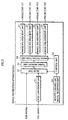
- FIG. 3 is a block diagram showing the structure of the projector 101.
- the projector 101 is made up of an external communication unit 21, a control unit 22, a brightness decreasing characteristic memory unit 23, a lighting hours memory unit 24, a lamp lighting circuit 25, a projection lamp 26, a timer unit 27, a brightness correction unit 28, a display-device driving unit 29, a display device unit 30, a projection lens unit 31, a remote-controller signal reception unit 32, a lamp-replacement detection unit 33, and the like.
- the external communication unit 21 communicates with external communication units of the projectors 102-104, so as to acquire information that indicates brightness for corresponding lamps (brightness information), and to provide their own brightness information to the other projectors.
- the brightness information is lighting hours accumulated since the lamp operating start for each projector (occasionally simply referred to as "lighting hours").
- the control unit 22 is made up of a CPU, a ROM for storing a control program and so on, a RAM that includes a table for temporarily storing lighting hours data of the other projectors acquired by communication, an EEPROM, and the like.
- the control unit 22 controls each unit included in the projector 101 so as to facilitate smooth image display.
- control unit 22 refers to its own brightness information and the brightness information of the other projectors obtained through the external communication unit 21, and when necessary, instructs the brightness correction unit 28 to correct the brightness of its own projection picture, so that the projection picture will produce the same brightness as those of the other projectors 102-104. Greater details will be given later.
- the brightness decreasing characteristic memory unit 23 has a look up table (LUT) in which an average brightness decreasing characteristic is recorded, where the average brightness decreasing characteristic has resulted by conducting tests on the relation between lighting hours and brightness decrease with use of a plurality of same kind of lamps, and then taking an average.
- LUT look up table
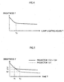
- FIG. 4 is a graph illustrating an example of the average brightness decreasing characteristic of the projection lamp 26. As shown in this graph, generally in the high-pressure discharge lamp such as xenon lamps, the brightness decreases rapidly from the lighting start to a certain time T0, and then moves onto a gradual decrease where the decrease rate is almost constant.
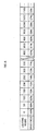
- FIG. 6 shows an example of LUT showing the described brightness decreasing characteristic.
- the control unit 22 reads the lighting hours information of the lamp, from the lighting hours memory unit 24, and estimates the current brightness of the projection lamp 26, by referring to the aforesaid LUT. It should be noted that the lighting hours between those listed in this diagram are obtainable by interpolating as appropriate, by using publicly-known linear interpolation or the like.
- the lighting hours memory unit 24 is to store an accumulated value of the lighting hours of the projection lamp 26.
- the lamp lighting circuit 25 upon reception of a lighting instruction from the control unit 22, generates a high-voltage pulse, thereby causing the projection lamp 26 to start discharge. Thereafter, the lamp lighting circuit 25 performs constant-power control so as to have the projection lamp 26 to emit a constant light flux, and stops the power supply to the projection lamp 26, upon receiving an extinguishing instruction from the control unit 22.
- the timer unit 27 resets the stored time to start counting, every time the control unit 22 issues a lighting instruction to the lamp lighting circuit 25.
- the control unit 22 when issuing an extinguishing instruction, adds the counted time so far to the time stored in the lighting hours memory unit 24, to update the lighting hours with the resulting hours by the adding.
- the brightness correction unit 28 controls the signal value (voltage) of the image signal so that the resulting brightness will have a desired value, then outputs the image signal to the display-device driving unit 29.
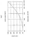
- the brightness correction unit 28 includes therein a nonvolatile memory (not shown) for storing a LUT showing gamma characteristic of the display device unit 30.
- This gamma characteristic represents a relation between the signal value (voltage value) of an inputted image signal and the brightness of a transmitted light in the display device unit 30.
- FIG . 7 shows one example of the gamma characteristic, where the lengthwise axis signifies the voltage value of the image signal, and the longitudinal axis signifies the light output (brightness) of the projection lamp 26, respectively in unit of percentage.
- the brightness correction unit 28 receives a brightness change instruction together with a corresponding target brightness value information, obtains the amount of voltage to be changed by referring to the gamma characteristic LUT described above. According to this, the brightness correction unit 28 changes the voltage value of the image signal, thereby changing the brightness of the projection picture.
- the voltage of the image signal is required to be reduced by about 10%.
- the display-device driving unit 29 drives the display device unit 30 according to the image signal after undergoing the brightness correction, so as to have it form an image.
- the display device unit 30 is for example a translucent color liquid crystal panel, and the image formed therein is projected onto a screen not shown in the drawing via the projection lens unit 31 by being irradiated by the projection lamp 26.
- the projection lens unit 31 contains therein a projection lens and a lens driving mechanism for focusing and zooming.
- the projection lens unit 31 performs the focusing/zooming in response to instructions from the control unit 22.
- the remote signal reception unit 32 receives an instruction from the remote controller 80 through infrared radiation communication, and conveys the content of the instruction to the control unit 22.
- the lamp-replacement detection unit 33 detects an incident of replacement of the projection lamp 26, and notifies the control unit 22 of the incident.
- the control unit 22 in response to reception of the notification, resets the lighting hours stored in the lighting hours memory unit 24.
- the lamp-replacement detection unit 33 may be implemented as follows. That is, a limit switch is provided, which is set ON (or OFF) when the lamp base is set to the socket portion of the projection lamp 26. Then when the limit switch is changed from ON to OFF (or vice versa), it is designed to detect that the replacement of the projection lamp 26 is performed.
- a photoelectric sensor which is used to detect the strength of the light flux of the projection, lamp 26, may be provided inside the projector 101 where it does not obstruct the image projection.
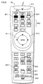
- FIG. 8 shows an example of the structure of the operation buttons of the remote controller 80 used for operating the multidisplay apparatus.
- the remote controller 80 includes a power ON button 801, a power OFF button 802, a source-selection button group 803 for selecting the source of an image signal, a brightness automatic-correction instruction button 804, a function button 805, a brightness manual-adjustment mode button 806, an ID select button 807, an all-apparatus selection button 808, a switch 809 for switching the transmission destination between a projector and the image distribution apparatus, a four-direction switch 810, an enter button 811, and the like.
- the projectors 101-104 are assigned an apparatus ID (e.g. simply 1-4).
- apparatus ID e.g. simply 1-4.
- the all-apparatus selection button 808 should be pushed.
- the brightness correction operation is performed automatically at a predetermined time interval.
- the brightness automatic-correction instruction button 804 should be pushed.
- the brightness manual-adjustment mode button 806 is used when the user intends to manually correct the brightness of each projector independently.
- the present remote controller 80 is structured to communicate with the projectors 101-104 and with the image distribution apparatus 100, using infrared radiation communication, and the reference numeral 812 represents a lighting unit for such infrared radiation.
- the projection lamp 26 will have different brightness from those of other projection lamps at the time T2, because it was new at the time T1 and so its brightness has a large decreasing rate (FIG. 5, the dotted line portion) compared to those of the other projectors 102-104 (FIG. 5, the solid line portion).
- FIG. 9 is a flowchart showing the contents of the brightness correction operation that the control unit 22 performs. In this embodiment, this operation is performed automatically after the power is turned on to the projector 101. However, not limited to this, it is also possible to perform the operation in response to the user instruction through the remote controller 80 and the like. Note that “projector” is simply called “apparatus” in the following explanation of the flowchart.
- lighting hours data of an apparatus is read from its own lighting hours memory unit 24, and is transmitted, as the brightness information of the apparatus, to the other projectors 102-104, using a publicly-known communication protocol and through the external communication unit 21 (Step S1).
- the lighting hours data is assigned apparatus IDs respectively for destination and origin, as header information.
- the other apparatuses also transmit their own lighting hours data to the apparatus.
- the apparatus will receive the lighting hours data (brightness information) of the other apparatuses together with a corresponding apparatus ID, one after another (Step S2). In reception, it is possible to perform publicly-known congestion control so that the transmissions from the apparatuses will not collide with each other.
- Step S3 it is judged whether reception of the lighting hours data from all the other apparatuses is complete, and if judging negatively, the control will be returned to Step S2, and reception operation is repeated. If judging affirmatively, the control will move to the next Step S4, and the received lighting hours data and the lighting hours data for the apparatus itself are stored in the table contained in the RAM of the control unit 22, in association with the apparatus IDs. Note here that the order of the operations of Step S3 and S4 may be changed, and that every time the lighting hours data is received, the data will be sequentially stored in the table.
- Step S5 the apparatus having the longest lighting hours is detected (i.e. the apparatus whose brightness is the lowest)
- Step S6:YES the apparatus having the longest lighting hours
- Step S6:YES it is necessary to adjust the brightness to that of the other apparatus. Therefore estimation is performed as to the lamp brightness of the other apparatus, from the brightness decreasing characteristic LUT stored in the brightness decreasing characteristic memory unit 23 (Step S7), and instructs the brightness correction unit 28 to correct the brightness of the projection picture of the apparatus itself (Step S8).
- the estimation which is obtained based on the brightness decreasing characteristic stored in the brightness decreasing characteristic memory unit 23, is the lamp's brightness.
- the brightness correction unit 28 has to decrease the voltage of the image signal so that the brightness of the projection picture will decrease so as to correspond to the lamp's brightness decrease (Step S8).
- the lamp brightness of the apparatus is obtained from the lighting hours of the apparatus and the brightness decreasing characteristic, and is set as Yp.
- the aforesaid lowest lamp brightness is set as Yq.
- the change in voltage value of the image signal when the projection picture's brightness becomes Yq/Yp is obtained, using the gamma characteristic of FIG. 7. Then correction is performed by changing the original voltage value by the obtained amount.
- the amount of change is stored in the nonvolatile memory of the brightness correction unit 28, for example, and is relied on for brightness correction until being updated in the brightness correction operation performed thereafter.
- Step S6 if the apparatus having the longest lighting hours is not any of the other apparatuses (i.e. when the apparatus's lamp lighting hours are the longest), then it is not necessary to correct the apparatus's brightness. Therefore Step S7 and S8 will be skipped.
- Step S9 it is judged whether a predetermined time has passed after the operation start of Step S1. If judging affirmatively, the control will be returned to Step S1, and operations of Step S1-S8 will be repeated.
- the decreasing speed of lamp brightness is not so fast, and so it is sufficient to set the predetermined time as about 10 hours, for example. Therefore it is designed to reset the counted time and to give an instruction to perform Step S1, when the IC clock (not shown) within the control unit 22 has counted 10 hours.
- control units 22 of the other apparatuses are to perform the similar operations as the aforesaid brightness correction operation. Therefore needless to say, the predetermined time and the counting start time should be the same for all the apparatuses.
- the apparatus to communicate with the other apparatuses, for synchronizing all the counting units.
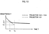
- FIG. 10 is a graph predicting the brightness change both for the projector 101 (broken line), and for the projectors 102-104 (solid line), where the brightness amendment is performed at the time T1 shown in FIG. 5, and the brightness correction operation is performed at the time T2.
- the brightness of the projector 101 falls below that of the other projectors.
- the brightness of the projector 101 decreases in about the same way as that of the other projectors, and so there will be little brightness difference among all the projectors.
- the interval between T1 and T2 is set intentionally large, and so the difference is obvious between the brightness of the projector 1 and that of the projectors 102-104.
- the actual interval of brightness correction operation is substantially shorter (10 hours in the aforementioned embodiment), and so all the projectors can produce the same brightness at almost all the times.
- the brightness decreasing characteristic LUT stored in the brightness decreasing characteristic memory unit 23, is an average characteristic of the projection lamp 26 of the same kinds.
- the projection lamp 26 used happened to have brightness decreasing rate larger than average lamps, there will be a difference between the actual lamp brightness and the lamp brightness estimated from the LUT in the brightness decreasing characteristic memory unit 23 (refer to FIG.11, where the solid line signifies an average brightness decreasing characteristic, and the broken line signifies a brightness decreasing characteristic of a projection lamp 26 that has a larger rate in brightness decrease.
- the scale used for the longitudinal axis (brightness) is set larger than those used in FIGs. 4, 5, and 10, so as to emphasize the difference in brightness decrease). In this case, the operation of FIG. 9 may not be able to completely correct the brightness difference between each projection pictures.
- FIG. 12 is a flowchart showing an example of a brightness correction operation that can deal with such a case. Please note that, just as in FIG. 9, this control is also performed immediately after the power is turned on to the projector, but not limited to such.
- correction coefficient a coefficient for correcting the brightness decreasing characteristic of the brightness decreasing characteristic memory unit 23 (hereinafter “correction coefficient”) is set. Note that this correction coefficient's default is set as “1" at the time of apparatus assembly and the like, and is stored in a nonvolatile memory, such as an EEPROM in the control unit 22. This example is characterized by enabling the correction coefficient to be updated when an adjuster has manually adjusted the brightness.
- Step S11 it is judged whether manual brightness adjustment has been performed. This means that, in a case where a user observes that only the projector 101 has low brightness on its projection picture compared to the other projectors 102-104 in spite of regular automatic brightness corrections, then either the user or a mechanic can adjust the brightness of the projector 101 by operating the remote controller 80 (FIG.8).
- An operation example is described as follows. First, an instruction is given to the image distribution apparatus 100 via an operation unit (unshown) or the remote controller 80, so that an image signal corresponding to "white" all over a screen is to be outputted.
- the brightness adjustment mode button 806 is pushed while the function button 805 is being pushed. Then, the ID select button 807 and the apparatus ID number "1" for the projector 101 are pushed in this order. Finally, the enter button 811 is pushed.
- the remote controller 80 is set to be communicable only with the projector 101, and the projector 101 is set to be in the brightness adjustment mode. Then, one of the up/down keys of a four-direction button 812 is pushed, to change the signal value of the image signal that the brightness correction unit 28 outputs, and to adjust the brightness of the projection picture of the projector 101 to be the same as the brightness of the projection pictures of the projectors 102-104.
- the manual brightness adjustment performed by the projector 101 is ended by pushing the enter button 811.
- Step S11 it is possible to set a flag in the RAM of the control unit 22, which indicates that the instruction for switching to the brightness adjustment mode is received from the remote controller 80. Such an arrangement facilitates the judgment of Step S11, because Step S11 can be performed only by checking this flag.
- Step S21 the control will be moved to Step S21, and the correction coefficient is obtained for correcting the brightness decreasing characteristic of the brightness decreasing characteristic memory unit 23.
- the obtained correction coefficient is then used to update the value of the correction coefficient stored in the EEPROM of the control unit 22.
- the correction coefficient is obtainable in the following way, for example.
- the value of the image signal, outputted to the display-device driving unit from the brightness correction unit 28, is stored in the RAM of the control unit 22, and is compared with the image signal value after the brightness adjustment. Then, a change in brightness of the projection picture, which corresponds to the change in signal value, is obtained using the above-described gamma characteristic.
- the brightness before brightness adjustment is Ya
- the brightness after the adjustment is Yb (here, Yb>Ya). Then the brightness is considered to be Yb/Ya of the unadjusted brightness .
- the lamp brightness has deviation of the ratio of Ya/Yb, with respect to the average brightness decreasing characteristic.
- actual brightness estimation has been performed using the average brightness decreasing characteristic, automatically.
- the accurate brightness value of the projection lamp actually used can be obtained by setting the value of Ya/Yb as the correction coefficient n, and by multiplying, by the value n, the brightness value obtained from the corresponding lighting hours in the average brightness decreasing characteristic LUT.
- the flowchart of FIG.12 is almost the same as the flowchart of FIG. 9, except that the aforesaid Steps S11 and S21 are added, and that the brightness information includes the correction coefficient besides the lighting hours. Therefore, the steps are only briefly explained in the following.
- Step S12 lighting hours data and a correction coefficient of the apparatus are transmitted to the other apparatuses, as brightness information. Meanwhile, lighting hours and correction coefficients of the other apparatuses are received, as brightness information (Step S13). Just as in the case of FIG. 9, the brightness information is assigned apparatus IDs respectively for origin and destination.
- the lamp brightness of each apparatus is estimated from the lighting hours and the correction coefficients stored in the table (Step S16). Specifically, a true value of brightness is estimated by multiplying, by the correction coefficient n, the provisional brightness value obtained from the brightness decreasing characteristic LUT.
- Step S17 the apparatus whose estimated brightness is the lowest is detected, and at Step S18, judgment is performed as to whether it is one of the other apparatuses, and if the judgment results in the affirmative, correction is performed so as to correct brightness of the projection picture of the apparatus itself, in accordance with the brightness of the other apparatus (Step S19).
- Step S19 is skipped and the control is moved to Step S20.
- Step S20 is for making the control move to Step S11 after a predetermined time, for the purpose of managing the time in this flowchart.
- the projectors 101-104 are designed to exchange brightness information, and to respectively perform brightness correction as necessary.
- the image distribution apparatus is designed to perform brightness correction.
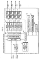
- FIG.13 is a block diagram showing the structure of an image distribution apparatus 200 relating to the second embodiment.
- the components assigned the same reference numeral have the same structure as in the first embodiment, and so will not be described here. In the following, only the structures unique to the present embodiment are described.
- four brightness correction units 71-74 which correspond to the projectors 101-104, are provided in the image distribution apparatus 200, respectively behind the image enlargement units 51-54.
- the brightness decreasing characteristic memory unit 63 stores a LUT showing the average brightness decreasing characteristic of a projection lamp, which was mentioned above. Furthermore, the lighting hours memory unit 64 stores, for each projectors 101-104, the accumulated lighting hours since the operating start of a corresponding projection lamp. When a projection lamp is replaced for any of the projectors 101-104, the operator inputs the incident using the remote controller or the operating unit not shown in the drawing. In response, the control unit 62 resets the lighting hours of the projector whose lamp has been replaced, to 0.
- the timer unit 62 counts the lighting hours . (Here, since the four projectors are lit/extinguished at the same time, individual counting of time is not necessary.) The control unit 62 performs addition of the counted time for each projector, so as to update the respective lighting hours.
- control unit 62 directly reads the contents from the lighting hours memory unit 64, which is used to estimate the brightness of each projector based on the LUT of brightness decreasing characteristic stored in the brightness decreasing characteristic memory unit 63.
- the control unit 62 then controls the brightness correction units 71-74 so that the other three projectors are adjusted to produce the brightness that is the same as the lowest brightness of all the four projectors.
- the projectors 101-104 do not have to have an external communication unit 21, a timer unit 27, a brightness decreasing characteristic memory unit 23, a lighting hours memory unit 24, and so on. This is advantageous in restraining the cost of manufacturing a projector to be low.
- a control unit for brightness correction operation may be structured as an independent brightness management apparatus in some instances, unlike in the first and second embodiments, where such a control unit is included either in the image distribution apparatus or in each projector.
- FIG.14 illustrates one example of such a system structure.
- a notebook personal computer 130 is used as the brightness management apparatus.
- the personal computer 130 has a wireless LAN function for example, through which it is network connected to the projectors 101-104.
- a nonvolatile memory within the personal computer 130 stores a LUT indicating the brightness decreasing characteristic.
- the personal computer 130 performs the functions performed by control unit 62 and the brightness decreasing characteristic memory unit 63 that are described in FIG. 13.
- the structure of each of the projectors 101-104 is the same as shown in FIG. 3, except that a wireless LAN communication unit is provided instead of the external communication unit 21, and that the brightness decreasing characteristic memory unit 23 is no more necessary.
- Either a user or a mechanic installs the program for executing the similar flowchart to FIG.9, in the hard disk of the personal computer 130, and executes the program.
- Step S1 will be "brightness information transmission request is transmitted to each projector".
- the projectors are configured to transmit their own brightness information to the personal computer 130, on receiving the transmission request of Step S1. These pieces of brightness information are in turn received in the personal computer 130, and are stored in the internal table. The personal computer 130 will then estimate the brightness of the projector whose lighting hours are the longest, based on the brightness decreasing characteristic LUT.
- the amount of brightness correction to be performed is calculated for each of the other projectors, the amount being necessary for the projector to have the same brightness as the lowest brightness of all the projectors.
- the personal computer 130 through the wireless LAN, instructs the other projectors to perform brightness correction according to the calculated amount of brightness correction.
- control unit 22 controls the brightness correction unit 28, so as to correct the brightness of its own projection picture.
- the multidisplay apparatus of the present invention enables automatic brightness adjustment directed to projection pictures of respective image display apparatuses, thereby enabling the same brightness throughout the pictures.
- one continuous screen is obtained, from which the viewers will hardly notice the fact that the screen is constituted by a plurality of projection pictures of a plurality of image display apparatuses.
- the present invention is appropriate for image display in sites of concerts and events, where a large screen with excellent image quality is required.
Landscapes
- Physics & Mathematics (AREA)
- General Physics & Mathematics (AREA)
- Engineering & Computer Science (AREA)
- Multimedia (AREA)
- Signal Processing (AREA)
- Controls And Circuits For Display Device (AREA)
- Projection Apparatus (AREA)
- Transforming Electric Information Into Light Information (AREA)
Applications Claiming Priority (3)
| Application Number | Priority Date | Filing Date | Title |
|---|---|---|---|
| JP2002145821 | 2002-05-21 | ||
| JP2002145821 | 2002-05-21 | ||
| PCT/JP2003/006316 WO2003098344A1 (en) | 2002-05-21 | 2003-05-21 | Image display device, multi-display device, and luminance management device |
Publications (2)
| Publication Number | Publication Date |
|---|---|
| EP1513007A1 true EP1513007A1 (de) | 2005-03-09 |
| EP1513007A4 EP1513007A4 (de) | 2005-06-29 |
Family
ID=29545099
Family Applications (1)
| Application Number | Title | Priority Date | Filing Date |
|---|---|---|---|
| EP03730533A Withdrawn EP1513007A4 (de) | 2002-05-21 | 2003-05-21 | Bildanzeigeeinrichtung, mehrfachanzeigeeinrichtung und luminanzverwaltungseinrichtung |
Country Status (5)
| Country | Link |
|---|---|
| US (1) | US7589695B2 (de) |
| EP (1) | EP1513007A4 (de) |
| JP (1) | JP4044930B2 (de) |
| KR (1) | KR100945339B1 (de) |
| WO (1) | WO2003098344A1 (de) |
Cited By (2)
| Publication number | Priority date | Publication date | Assignee | Title |
|---|---|---|---|---|
| EP2685314A1 (de) * | 2012-07-12 | 2014-01-15 | CJ CGV Co., Ltd. | Projektionsvorrichtungsverwaltungssystem |
| CN103765311A (zh) * | 2012-07-12 | 2014-04-30 | Cjcgv株式会社 | 投射装置管理系统 |
Families Citing this family (36)
| Publication number | Priority date | Publication date | Assignee | Title |
|---|---|---|---|---|
| US8624895B2 (en) | 2005-01-20 | 2014-01-07 | Production Resource Group, Llc | Controls for digital lighting |
| US20060279494A1 (en) * | 2005-06-13 | 2006-12-14 | I-Hwei Yen | Color compensation system and color compensation method for a display |
| TW200702891A (en) * | 2005-07-15 | 2007-01-16 | Coretronic Corp | Projector, and a control method of the bulb brightness for the projector |
| TWI283994B (en) * | 2005-11-08 | 2007-07-11 | Lumens Digital Optics Inc | Brightness adjusting device for video wall system and method therefor |
| JP5011730B2 (ja) * | 2006-01-18 | 2012-08-29 | 富士ゼロックス株式会社 | 画像形成装置、サブユニットの交換方法、及び画像形成装置の保守方法 |
| US20080024674A1 (en) * | 2006-02-06 | 2008-01-31 | Toshiba America Consumer Products, Llc. | Brightness control system and method |
| KR100791267B1 (ko) * | 2006-02-20 | 2008-01-04 | 이화여자대학교 산학협력단 | 멀티 프로젝터의 밝기 보정 방법 |
| KR100786572B1 (ko) * | 2006-04-25 | 2007-12-21 | 주식회사 유니텍 | 다중 영상신호를 이음매 없이 대형화면에 표출하는신호처리장치 |
| US7635188B2 (en) * | 2006-06-06 | 2009-12-22 | Barco Lighting Systems, Inc. | Method and apparatus for creating a collage from a plurality of stage lights |
| US8016433B2 (en) * | 2007-03-09 | 2011-09-13 | Sony Corporation | Projector and control method thereof |
| JP5136824B2 (ja) * | 2007-03-09 | 2013-02-06 | ソニー株式会社 | プロジェクタおよびその制御方法 |
| JP2008224870A (ja) * | 2007-03-09 | 2008-09-25 | Sony Corp | プロジェクタおよびその制御方法 |
| JP4433320B2 (ja) * | 2007-03-09 | 2010-03-17 | ソニー株式会社 | プロジェクタおよびその制御方法 |
| JP5109527B2 (ja) * | 2007-08-03 | 2012-12-26 | ソニー株式会社 | 画像形成装置およびその制御方法、並びにプログラム |
| JP5126489B2 (ja) * | 2007-09-14 | 2013-01-23 | セイコーエプソン株式会社 | プロジェクタ、制御システムおよび制御方法 |
| US20090153390A1 (en) * | 2007-12-18 | 2009-06-18 | Zackschewski Shawn R | Arbitration system and method for use with wireless remote control devices in a multiple video screen entertainment system |
| US20110181572A1 (en) * | 2007-12-28 | 2011-07-28 | E.I. Dupont De Nemours And Company | Electronic devices operable to use adjusted data signals and processes of making and using the same |
| US20090167782A1 (en) * | 2008-01-02 | 2009-07-02 | Panavision International, L.P. | Correction of color differences in multi-screen displays |
| US20090179836A1 (en) * | 2008-01-10 | 2009-07-16 | Premier Image Technology(China) Ltd. | Gamma correction method, gamma correction apparatus, and display device |
| JP2009223230A (ja) * | 2008-03-18 | 2009-10-01 | Casio Comput Co Ltd | 投影装置、投影装置の制御方法及びプログラム |
| US20100134690A1 (en) * | 2008-12-03 | 2010-06-03 | Sanyo Electric Co., Ltd. | Television receiver |
| US8378960B2 (en) * | 2009-08-13 | 2013-02-19 | International Business Machines Corporation | Apparatus, system, and method for controlling an electronic display |
| KR101727287B1 (ko) * | 2010-02-08 | 2017-04-14 | 엘지전자 주식회사 | 멀티프로젝션 시스템 및 이를 이용한 영상 투사 방법 |
| JP2012150149A (ja) * | 2011-01-17 | 2012-08-09 | Mitsubishi Electric Corp | マルチ画面表示装置 |
| CN103354936B (zh) | 2011-02-10 | 2016-08-10 | 夏普株式会社 | 多重显示装置和图像显示装置 |
| WO2012119215A1 (en) * | 2011-03-04 | 2012-09-13 | Eski Inc. | Devices and methods for providing a distributed manifestation in an environment |
| JP6011157B2 (ja) * | 2011-09-05 | 2016-10-19 | 株式会社リコー | 投影システム、投影装置、センサ装置、発電制御方法及び発電制御プログラム |
| US8525752B2 (en) | 2011-12-13 | 2013-09-03 | International Business Machines Corporation | System and method for automatically adjusting electronic display settings |
| US9240135B2 (en) * | 2013-06-12 | 2016-01-19 | Lighthouse Technologies, Ltd. | Chromaticity adjustment for LED video screens |
| JP6289049B2 (ja) * | 2013-11-20 | 2018-03-07 | 三菱電機株式会社 | マルチ画面表示装置 |
| JP6659129B2 (ja) * | 2015-12-03 | 2020-03-04 | キヤノン株式会社 | 投影装置及びその制御方法、投影システム |
| JP6707870B2 (ja) * | 2016-01-20 | 2020-06-10 | セイコーエプソン株式会社 | 投写システムおよび投写位置検出方法 |
| JP2017211627A (ja) * | 2016-05-23 | 2017-11-30 | パナソニックIpマネジメント株式会社 | 映像表示装置、映像表示システム、映像表示装置の輝度調整方法 |
| US10504428B2 (en) | 2017-10-17 | 2019-12-10 | Microsoft Technology Licensing, Llc | Color variance gamma correction |
| US10657901B2 (en) | 2017-10-17 | 2020-05-19 | Microsoft Technology Licensing, Llc | Pulse-width modulation based on image gray portion |
| CN115190281B (zh) * | 2022-06-30 | 2024-01-02 | 海宁奕斯伟集成电路设计有限公司 | 调整投影仪投影位置的装置及方法 |
Family Cites Families (13)
| Publication number | Priority date | Publication date | Assignee | Title |
|---|---|---|---|---|
| US4061911A (en) * | 1976-04-14 | 1977-12-06 | Audio Visual Innovators Corporation | Automatically switched spare lamp for a light projector |
| JPH0273241A (ja) * | 1988-09-08 | 1990-03-13 | Hitachi Ltd | 投射形ディスプレイのスクリーン明るさ制御方法及び装置 |
| KR950008134B1 (ko) * | 1991-05-24 | 1995-07-25 | 가부시끼가이샤 히다찌세이사꾸쇼 | 멀티스크린 디스플레이 장치 |
| US5581075A (en) * | 1993-10-06 | 1996-12-03 | Nikon Corporation | Multi-beam scanning projection exposure apparatus and method with beam monitoring and control for uniform exposure of large area |
| JPH09138368A (ja) * | 1995-11-14 | 1997-05-27 | Chiyoda Corp | 合成映像表示システム |
| EP1395092B1 (de) * | 1996-04-10 | 2006-05-31 | Seiko Epson Corporation | Lichtquelleneinheit, Lichtquellengerät und Projektionsanzeigengerät |
| JPH1090645A (ja) | 1996-09-12 | 1998-04-10 | Matsushita Electric Ind Co Ltd | 液晶表示装置 |
| JP2000338941A (ja) * | 1999-05-27 | 2000-12-08 | Seiko Epson Corp | 投射型表示装置 |
| JP2001056517A (ja) * | 1999-08-19 | 2001-02-27 | Sony Corp | 投射型ディスプレイ装置 |
| JP2001142145A (ja) | 1999-11-16 | 2001-05-25 | Nec Corp | プロジェクタ |
| JP3703361B2 (ja) | 2000-03-07 | 2005-10-05 | 株式会社日立製作所 | マルチスクリーン表示装置、表示システム及びこれらに用いるプロジェクタ駆動回路 |
| US6804406B1 (en) * | 2000-08-30 | 2004-10-12 | Honeywell International Inc. | Electronic calibration for seamless tiled display using optical function generator |
| AU2002356382A1 (en) * | 2002-01-02 | 2003-07-15 | Philips Intellectual Property And Standards Gmbh | Image projector and method of operating same |
-
2003
- 2003-05-21 KR KR1020047018735A patent/KR100945339B1/ko not_active Expired - Fee Related
- 2003-05-21 WO PCT/JP2003/006316 patent/WO2003098344A1/ja not_active Ceased
- 2003-05-21 JP JP2004505801A patent/JP4044930B2/ja not_active Expired - Fee Related
- 2003-05-21 EP EP03730533A patent/EP1513007A4/de not_active Withdrawn
- 2003-05-21 US US10/514,088 patent/US7589695B2/en not_active Expired - Lifetime
Non-Patent Citations (2)
| Title |
|---|
| No further relevant documents disclosed * |
| See also references of WO03098344A1 * |
Cited By (5)
| Publication number | Priority date | Publication date | Assignee | Title |
|---|---|---|---|---|
| EP2685314A1 (de) * | 2012-07-12 | 2014-01-15 | CJ CGV Co., Ltd. | Projektionsvorrichtungsverwaltungssystem |
| CN103765311A (zh) * | 2012-07-12 | 2014-04-30 | Cjcgv株式会社 | 投射装置管理系统 |
| EP2857898A1 (de) * | 2012-07-12 | 2015-04-08 | CJ CGV Co., Ltd. | Projektionsvorrichtungsverwaltungssystem |
| CN103765311B (zh) * | 2012-07-12 | 2015-07-15 | Cjcgv株式会社 | 投射装置管理系统 |
| US9134594B2 (en) | 2012-07-12 | 2015-09-15 | Cj Cgv Co., Ltd | Projection device management system |
Also Published As
| Publication number | Publication date |
|---|---|
| JPWO2003098344A1 (ja) | 2005-09-22 |
| KR100945339B1 (ko) | 2010-03-08 |
| US20050219271A1 (en) | 2005-10-06 |
| EP1513007A4 (de) | 2005-06-29 |
| JP4044930B2 (ja) | 2008-02-06 |
| US7589695B2 (en) | 2009-09-15 |
| KR20040111665A (ko) | 2004-12-31 |
| WO2003098344A1 (en) | 2003-11-27 |
Similar Documents
| Publication | Publication Date | Title |
|---|---|---|
| US7589695B2 (en) | Image display apparatus, multidisplay apparatus, and brightness management apparatus | |
| JP4281593B2 (ja) | プロジェクタの制御 | |
| JP5971973B2 (ja) | 投影装置 | |
| US10341626B2 (en) | Image projection system, projector, and control method for image projection system | |
| EP1118977A1 (de) | Projektionsanzeigevorrichtung | |
| JP4552986B2 (ja) | 画像表示装置 | |
| US20110164192A1 (en) | Projector and method of controlling the same | |
| US7841723B2 (en) | Projector using lamp, method and program for controlling discharge lamp light source | |
| US10148924B2 (en) | Projection apparatus, method of controlling projection apparatus, and projection system | |
| JP2016163228A (ja) | 表示装置 | |
| JP2007226052A (ja) | プロジェクタ設定システムおよびプログラム | |
| JP2003295321A (ja) | プロジェクタ制御装置 | |
| US12368829B2 (en) | Control method and display system | |
| JP5979833B2 (ja) | 投影装置及びその制御方法 | |
| JP5127256B2 (ja) | 投射型表示装置 | |
| US11206379B2 (en) | Controlled apparatus and control method thereof | |
| US10965922B2 (en) | Display device having function for eliminating burn-in and method for controlling display device | |
| JP2007178636A (ja) | 投射型映像表示装置 | |
| JP2017083647A (ja) | 投影装置、及び投影方法 | |
| KR100863843B1 (ko) | 투사형 영상표시기기의 제어장치 및 방법 | |
| JP2009015197A (ja) | 画像表示装置及びその制御方法 | |
| JP2023015486A (ja) | 制御装置、画像投射システム、制御方法、およびプログラム | |
| JP2008275723A (ja) | プロジェクタ | |
| JP2021148948A (ja) | 表示制御装置、表示装置および表示制御方法 | |
| JP2020092312A (ja) | 電子機器およびその制御方法 |
Legal Events
| Date | Code | Title | Description |
|---|---|---|---|
| PUAI | Public reference made under article 153(3) epc to a published international application that has entered the european phase |
Free format text: ORIGINAL CODE: 0009012 |
|
| 17P | Request for examination filed |
Effective date: 20041214 |
|
| AK | Designated contracting states |
Kind code of ref document: A1 Designated state(s): DE GB |
|
| A4 | Supplementary search report drawn up and despatched |
Effective date: 20050518 |
|
| RAP1 | Party data changed (applicant data changed or rights of an application transferred) |
Owner name: PANASONIC CORPORATION |
|
| 17Q | First examination report despatched |
Effective date: 20090320 |
|
| R17C | First examination report despatched (corrected) |
Effective date: 20090320 |
|
| GRAP | Despatch of communication of intention to grant a patent |
Free format text: ORIGINAL CODE: EPIDOSNIGR1 |
|
| INTG | Intention to grant announced |
Effective date: 20140124 |
|
| STAA | Information on the status of an ep patent application or granted ep patent |
Free format text: STATUS: THE APPLICATION IS DEEMED TO BE WITHDRAWN |
|
| 18D | Application deemed to be withdrawn |
Effective date: 20140604 |