EP1513228B1 - Verbinder mit Haltelement zum Festhalten eines Kabels - Google Patents
Verbinder mit Haltelement zum Festhalten eines Kabels Download PDFInfo
- Publication number
- EP1513228B1 EP1513228B1 EP04020640A EP04020640A EP1513228B1 EP 1513228 B1 EP1513228 B1 EP 1513228B1 EP 04020640 A EP04020640 A EP 04020640A EP 04020640 A EP04020640 A EP 04020640A EP 1513228 B1 EP1513228 B1 EP 1513228B1
- Authority
- EP
- European Patent Office
- Prior art keywords
- cable
- engaging member
- housing
- receiving
- receiving portion
- Prior art date
- Legal status (The legal status is an assumption and is not a legal conclusion. Google has not performed a legal analysis and makes no representation as to the accuracy of the status listed.)
- Expired - Lifetime
Links
Images

Classifications
-
- H—ELECTRICITY
- H01—ELECTRIC ELEMENTS
- H01R—ELECTRICALLY-CONDUCTIVE CONNECTIONS; STRUCTURAL ASSOCIATIONS OF A PLURALITY OF MUTUALLY-INSULATED ELECTRICAL CONNECTING ELEMENTS; COUPLING DEVICES; CURRENT COLLECTORS
- H01R13/00—Details of coupling devices of the kinds covered by groups H01R12/70 or H01R24/00 - H01R33/00
- H01R13/58—Means for relieving strain on wire connection, e.g. cord grip, for avoiding loosening of connections between wires and terminals within a coupling device terminating a cable
- H01R13/5804—Means for relieving strain on wire connection, e.g. cord grip, for avoiding loosening of connections between wires and terminals within a coupling device terminating a cable comprising a separate cable clamping part
- H01R13/5812—Means for relieving strain on wire connection, e.g. cord grip, for avoiding loosening of connections between wires and terminals within a coupling device terminating a cable comprising a separate cable clamping part the cable clamping being achieved by mounting the separate part on the housing of the coupling device
-
- H—ELECTRICITY
- H01—ELECTRIC ELEMENTS
- H01R—ELECTRICALLY-CONDUCTIVE CONNECTIONS; STRUCTURAL ASSOCIATIONS OF A PLURALITY OF MUTUALLY-INSULATED ELECTRICAL CONNECTING ELEMENTS; COUPLING DEVICES; CURRENT COLLECTORS
- H01R13/00—Details of coupling devices of the kinds covered by groups H01R12/70 or H01R24/00 - H01R33/00
- H01R13/58—Means for relieving strain on wire connection, e.g. cord grip, for avoiding loosening of connections between wires and terminals within a coupling device terminating a cable
- H01R13/5804—Means for relieving strain on wire connection, e.g. cord grip, for avoiding loosening of connections between wires and terminals within a coupling device terminating a cable comprising a separate cable clamping part
- H01R13/5816—Means for relieving strain on wire connection, e.g. cord grip, for avoiding loosening of connections between wires and terminals within a coupling device terminating a cable comprising a separate cable clamping part for cables passing through an aperture in a housing wall, the separate part being captured between cable and contour of aperture
-
- H—ELECTRICITY
- H01—ELECTRIC ELEMENTS
- H01R—ELECTRICALLY-CONDUCTIVE CONNECTIONS; STRUCTURAL ASSOCIATIONS OF A PLURALITY OF MUTUALLY-INSULATED ELECTRICAL CONNECTING ELEMENTS; COUPLING DEVICES; CURRENT COLLECTORS
- H01R13/00—Details of coupling devices of the kinds covered by groups H01R12/70 or H01R24/00 - H01R33/00
- H01R13/40—Securing contact members in or to a base or case; Insulating of contact members
- H01R13/42—Securing in a demountable manner
- H01R13/436—Securing a plurality of contact members by one locking piece or operation
- H01R13/4367—Insertion of locking piece from the rear
Definitions
- This invention relates to a connector having an engaging member engaged with a contact and holding a cable to be connected to the contact.
- An existing connector of the type comprises a housing and a cover member attached to the housing to cover an opening portion of the housing.
- the opening portion is formed at one end of a cavity defined in the housing and serves as an insertion port for insertion of a terminal metal as a contact member,
- a cable connected to the terminal metal is bent into a U shape and led out from the inside of the housing through the opening portion.
- the cable is clamped and held by the cover member and the opening portion of the housing.
- the cover member is provided with a stopper for inhibiting the terminal metal received in the housing from moving in a removing direction (for example, see Japanese Patent Application Publication (JP-A) No. H10-321281).
- the existing connector is disadvantageous in that an external dimension is increased because an outer periphery of the opening portion of the housing is covered with the cover member.
- cover member covering the outer periphery of the housing is often subjected to external force to be damaged and broken.
- the cable connected to the terminal metal is held by the cover member and the housing in a bent state. Therefore, a core wire of the cable may be applied with a stress.
- US 6,109,954 discloses a strain relief housing for use in a modular communication plug which has a divider member dividing a central bore of the plug into four channels, each channel being adapted to contain two conductors from the cable being terminated. Separation members extend from the rear of the divider to the rear of the housing and are insertable into the cable so that separation and segregation of the conductors actually commences within the cable. A compression ring surrounds the cable and is insertable within the rear of the plug housing where it is compressed to clamp or anchor the cable.
- EP 1 050 930 discloses a cable clamp for electric equipments consisting of a body which presents a substantially tubular portion, into which a cable for electric equipments is inserted, so as to pass through the tubular portion; the cable is clamped by means of corresponding clamping means consisting of a flexible portion of the body itself provided with at least one protrusion or tooth on its internal face, bending toward its longitudinal axis for clamping the cable after the body has been introduced into a bush or tige.
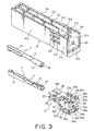
- a connector according to an embodiment of this invention comprises a plurality of conductive contacts 11, a housing 21 having a generally rectangular cylindrical shape and containing the contacts 11, and an engaging member 31 engaged with the housing 21.
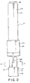
- the engaging member 31 is inserted into the housing 21 in an inserting direction I (see Fig. 2) through an opening portion 22 formed at one end of the housing 21 and is engaged with the housing 21.
- the engaging member 31 is drawn out from the housing 21 through the opening portion 22 in a removing direction II (see Fig. 2) opposite to the inserting direction I.
- Each of the contact 11 has a core wire crimping portion 13, a contacting portion 14 extending from one end of the core wire crimping portion 13 towards the inserting direction I, a coating crimping portion 15 extending from the other end of the core wire crimping portion 13 towards the removing direction II, and an engaging portion 16 extending from the coating crimping portion 15 towards the removing direction II.
- the core wire crimping portion 13 crimps a core wire 41a of a cable 41 and is connected to the core wire 41a.
- the contacting portion 14 is adapted to be connected to a mating contact of a mating connector (not shown).
- the coating crimping portion 15 crimps a coating portion 41b coating the core wire 41a of the cable 41.
- a pair of the cables 41 are bundled and covered with a sheath 41c.
- Two pairs of the cables 41 i.e., four cables 41 are received in the connector and connected to the contacts 11, four in number, in one-to-one correspondence although the two cables 41 are illustrated in the figures.
- the housing 21 has a first receiving portion 23 receiving the contacts 11, and a second receiving portion 24 receiving the engaging member 31.
- the first receiving portion 23 has four receiving sections defined in the housing 21 to receive the four contacts 11, respectively. As shown in Figs. 1 and 3, the first receiving portion 23 is formed by a pair of first side plates 21a, a pair of second side plates 21b, a first partitioning plate 21c, and a second partitioning plate 21d.
- the first side plates 21a are arranged in parallel to each other and faced to each other.
- the first side plates 21a are connected to the second side plates 21b.
- the housing 21 is formed by the first and the second side plates 21a and 21b into the rectangular cylindrical shape.
- the first partitioning plate 21c is arranged in parallel to the first side plates 21a and divides a space between the first side plates 21a.
- the second partitioning plate 21d is arranged in parallel to the second side plates 21b and divides a space between the second side plates 21b.
- the first and the second partitioning plates 21c and 21d intersect each other at right angles.
- an internal space defined by the first and the second side plates 21a and 21b forming the rectangular cylindrical shape is divided by the first and the second partitioning plates 21c and 21d to define the first receiving portion 23 having the four receiving sections.
- the first receiving portion 23 is divided in vertical and horizontal directions as seen from the opening portion 22.
- the second receiving portion 24 is formed by a pair of first engaging side plate 21n and a pair of second engaging side plates 21e continuously extending from the first and the second side plates 21a and 21b at one end of the housing 21 towards the removing direction II, respectively.
- the first engaging side plates 21 n are arranged in parallel to each other.
- the second engaging side plates 21e are arranged in parallel to each other.
- the second receiving portion 24 of the housing 21 is formed by the first and the second engaging side plates 21n and 21e into a rectangular cylindrical shape.
- a distance between the first engaging side plates 21n is slightly greater than that between the first side plates 21a.
- a distance between the second engaging side plates 21e is slightly greater than that between the second side plates 21b.
- Each of the first engaging side plates 21n is provided with a plurality of window portions 21f having a hole-like shape and formed adjacent to one ends of the first and the second partitioning plates 21c and 21d towards the removing direction II.
- the window portions 21f serve to inhibit the engaging member 31 from moving in the removing direction II when the engaging member 31 is received in the second receiving portion 24.
- the opening portion 22 of the housing 21 is located at one ends of the first and the second engaging plates 21n and 21e towards the removing direction II.
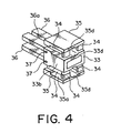
- the engaging member 31 has a base portion 33 of a generally rectangular cylindrical shape, a plurality of cable holding portions 34 formed on the base portion 33, a pair of guide plate portions 35 formed on the cable holding portions 34, respectively, and a pair of stopper portions 36 extending in the inserting direction I from an end face of the base portion 33 towards the inserting direction I.
- the base portion 33 has a pair of first planes 33a faced to each other in the vertical direction and a pair of second planes 33b connecting the first planes 33a.
- each of the first planes 33a On each of the first planes 33a, a pair of the cable holding portions 34 are formed. Each of the cable holding portion 34 has a long dimension in the inserting and the removing directions I and II. On each of the first planes 33a of the base portion 33, the cable holding portions 34 are spaced from each other in a direction III perpendicular to the inserting and the removing directions II.
- Each of the cable holding portions 34 has a first end and a second end towards the inserting and the removing directions I and II, respectively.
- the first end of the cable holding portion 34 is fixed to the first plane 33a.
- the cable holding portion 34 has an extending portion extending from the first end towards the second end and faced to the first plane 33a of the base portion 33 with a space kept therefrom.
- the cable holding portion 34 is elastically displacable in a plane parallel to the first plane 33a except the first end as a fixed end.
- the cable holding portions 34 are provided with first protrusions 34a formed at the second ends and protruding outward in the direction III. Further, the cable holding portions 34 are provided with second protrusions 34b formed at the second ends and protruding inward, i.e., protruding towards each other in the direction III.
- the extending portions of the cable holding portions 34 hold the cable 41 in cooperation with the housing 21.
- Each of the first planes 33a of the base portion 33 is provided with a first insert portion 33d as a long groove formed between the cable holding portions 34 and extending in the inserting and the removing directions I and II.
- Each of the guide plate portions 35 has a confronting surface 35a faced to the first plane 33a.
- the guide plate portions 35 are faced to the first planes 33a of the base portion 33 via the cable holding portions 34, respectively.
- the confronting surface 35a of each of the guide plate portions 35 is provided with a groove-like second insert portion 35d faced to the first insert portion 33d.
- a space between the first and the second insert portions 33d and 35d serves as an inserting portion adapted to insert each pair of the cables 41 covered with the sheath 41c. Namely, the first and the second insert portions 33d and 35d are cooperated with each other to form the inserting portion. In the space between the first and the second insert portions 33d and 35d, the second protrusions 34b of the cable holding portions 34 are protruded.
- Each of the stopper portions 36 is provided with a cutout portion 36a formed at one end towards the inserting direction I and extending therefrom in the removing direction II.
- the cutout portions 36a serve to receive the first partitioning plate 21c when the stopper portions 36 are inserted into the housing 21 above and below the second partitioning plate 21d, respectively. Further, the one ends of the stopper portions 36 towards the inserting direction I serve to prevent the contacts 11 received in the housing 21 from moving in the removing direction II.
- Each of the second planes 33b of the engaging member 31 is provided with a plurality of engaging protrusions 37 to be engaged with the window portions 21f in one-to-one correspondence when the engaging member 31 is received in the housing 21.
- Each of the housing 21 and the engaging member 31 may be formed by molding a resin material.
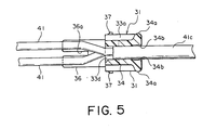
- each pair of the cables 41 bundled by the sheath 41 c are inserted into the space defined between the first and the second insert portions 33d and 35d at each of upper and lower portions of the engaging member 31.
- the two cables 41 are separated from each other. However, when the cables 41 are inserted through the space between the first and the second insert portions 33d and 35d, the cables 41 are overlapped with each other in a straight line.
- the cables 41 are connected to the contacts 11. Thereafter, the contacts 11 are inserted in the inserting direction into the first receiving portion 23 through the opening portion 22 of the housing 21 with the contacting portions 14 of the contacts 11 directed forward. Thus, the contacts 11 are received in the first receiving portion 23.
- the engaging member 31 is guided by the guide plate portions 35 and inserted into the second receiving portion 24 in the inserting direction I.
- the first protrusions 34a of the cable holding portions 34 are inserted in frictional contact with inner surfaces of the first engaging side plates 21 n of the second receiving portion 24. In this event, the first protrusions 34a are pressed inward so that the cable holding portions 34 are bent and displaced inward.
- the sheath 41c covering the cables 41 is pressed by the second protruding portions 34b forcedly displaced inward (by a moving distance C in Fig. 1).
- the cables 41 covered with the sheath 41c are tightened and held, via the sheath 41c, by the second protrusions 34b of the cable holding portions 34.
- the stopper portions 36 are inserted in the inserting direction I in parallel to the second partitioning plate 21d of the housing 21 above and below the second partitioning plate 21d, respectively.
- the first partitioning plate 21c enters into the cutout portions 36a formed in the stopper portions 36 to escape of the first partitioning plate 21c.
- the engaging protrusions 37 of the engaging member 31 are engaged with the window portions 21f of the housing 21. It is therefore possible to prevent the engaging member 31 from being released from the housing 21 in the removing direction II.
- the engaging member 31 is received in the second receiving portion 24, the one ends of the stopper portions 36 towards the inserting direction I are brought into contact with end faces of the engaging portions 16 of the contacts 11 to prevent the contacts 11 from moving in the removing direction II.
- the cables 41 covered with the sheath 41c may be inserted into the space between the first and the second insert portions 33d and 35d after the contacts 11 are connected to the cables 41. This is because no substantial stress is applied by the cable holding portions 34 upon the cables 41 covered with the sheath 41c when the cables 41 are inserted into the space between the first and the second insert portions 33d and 35d.
- the engaging member 31 is received in the second receiving portion 24. Therefore, the connector is reduced in external dimension. In addition, the engaging member 31 is prevented from being directly subjected to external force.
- the cables 41 are stretched in the housing 21 in the inserting and the removing directions I and II without being bent in a U shape. Therefore, the stress applied upon the cables 41 is minimized. In addition, limitation imposed upon the location of the connector is minimized.
- the cable holding portions 34 tighten and hold the sheath 41c covering the cables 41. Therefore, the stress applied upon the core wires 41a of the cables 41 is minimized.
- the engaging member 31 is provided with the cable holding portions 34, it is possible to reduce the load applied upon the connecting portion of the contact 11 and the cable 41 when external force is applied and to improve the reliability.
Landscapes
- Details Of Connecting Devices For Male And Female Coupling (AREA)
- Connector Housings Or Holding Contact Members (AREA)
Claims (8)
- Verbinder zum Anschließen eines Kabels (41) mit:einem Kontakt (11), der leitend und daran angepasst ist, an das Kabel angeschlossen zu werden,einem Gehäuse (21), das den Kontakt hält, undeinem Eingreifelement (31) das mit dem Gehäuse in Eingriff steht,wobei das Gehäuse einen ersten Aufnahmeabschnitt (23), der den Kontakt aufnimmt, und einen zweiten Aufnahmeabschnitt (24), der das Eingreifelement aufnimmt, enthält,das Eingreifelement einen Einfügeabschnitt (33d, 35d), in den das Kabel eingeführt werden soll, und einen Kabelhalteabschnitt (34) zum Halten des Kabels enthält, wobei er durch den zweiten Aufnahmeabschnitt elastisch verformt wird, wenn das Eingreifelement in den zweiten Aufnahmeabschnitt eingeführt wird,dadurch gekennzeichnet, dassdas Eingreifelement einen Basisabschnitt (33) und einen dem Basisabschnitt gegenüberliegenden Führungsplattenabschnitt (35) enthält undder Kabelhalteabschnitt (34) zwischen dem Basisabschnitt und dem Führungsplattenabschnitt angeordnet ist.
- Verbinder nach Anspruch 1, bei dem
der zweite Aufnahmeabschnitt (24) eine zylindrische Form aufweist und eine Eingreifseitenplatte (21n) enthält und
der Kabelhalteabschnitt (34) mit einem ersten Vorsprung (34a) versehen ist, der nach außen vorspringt, um mit der Eingreifseitenplatte in Kontakt gebracht zu werden, wenn das Eingreifelement (31) in den zweiten Aufnahmeabschnitt eingeführt wird. - Verbinder nach Anspruch 1 oder 2, bei dem der Kabelhalteabschnitt (34) weiter mit einem zweiten Vorsprung (34b) versehen ist, der zu dem Einfügeabschnitt (33d, 35d) hin vorspringt.
- Verbinder nach einem der Ansprüche 1 bis 3, bei dem der Kabelhalteabschnitt (34) einen Vorsprung (34b) aufweist, der zu dem Einfügeabschnitt hin vorspringt.
- Verbinder nach einem der Ansprüche 1 bis 4, bei dem das Eingreifelement (31) weiter einen zusätzlichen Kabelhalteabschnitt (34) enthält, der mit dem erstgenannten Kabelhalteabschnitt zum Halten des Kabels (41) zusammenwirkt, wobei er durch den zweiten Aufnahmeabschnitt (24) elastisch verformt wird, wenn das Eingreifelement in den zweiten Aufnahmeabschnitt eingeführt wird.
- Verbinder nach Anspruch 5, bei dem
der Basisabschnitt (33) eine erste Fläche (33a) und einen ersten Einfügeabschnitt (33d) aufweist, der auf der ersten Fläche gebildet ist,
der Führungsplattenabschnitt (35) eine konfrontierende Fläche (35a), die der ersten Fläche zugewandt ist, und einen zweiten Einfügeabschnitt (35d) aufweist, der auf der konfrontierenden Fläche gebildet ist, und
der erste und der zweite Einfügeabschnitt zusammenwirken zum Bilden des Einfügeabschnitts. - Verbinder nach Anspruch 1 oder 5, bei dem
der zweite Aufnahmeabschnitt (24) eine Zylinderform aufweist und eine Eingreifseitenplatte (21n) enthält, die mit einem Fensterabschnitt (21f) versehen ist, und
der Basisabschnitt (33) mit einem Eingreifvorsprung (37) versehen ist, der mit dem Fensterabschnitt (21f) in Eingriff kommen soll, wenn das Eingreifelement (31) in den zweiten Aufnahmeabschnitt eingeführt wird. - Verbinder nach einem der Ansprüche 1 bis 7, bei dem das Eingreifelement (31) einen Stopperabschnitt (36) aufweist, der mit dem Kontakt (11) in Eingriff steht, um zu verhindern, dass der Kontakt von dem ersten Aufnahmeabschnitt (23) zu dem zweiten Aufnahmeabschnitt (24) bewegt wird.
Applications Claiming Priority (2)
| Application Number | Priority Date | Filing Date | Title |
|---|---|---|---|
| JP2003313692A JP3998203B2 (ja) | 2003-09-05 | 2003-09-05 | コネクタ |
| JP2003313692 | 2003-09-05 |
Publications (2)
| Publication Number | Publication Date |
|---|---|
| EP1513228A1 EP1513228A1 (de) | 2005-03-09 |
| EP1513228B1 true EP1513228B1 (de) | 2007-02-14 |
Family
ID=34131890
Family Applications (1)
| Application Number | Title | Priority Date | Filing Date |
|---|---|---|---|
| EP04020640A Expired - Lifetime EP1513228B1 (de) | 2003-09-05 | 2004-08-31 | Verbinder mit Haltelement zum Festhalten eines Kabels |
Country Status (5)
| Country | Link |
|---|---|
| US (1) | US6948970B2 (de) |
| EP (1) | EP1513228B1 (de) |
| JP (1) | JP3998203B2 (de) |
| CN (1) | CN1309121C (de) |
| DE (1) | DE602004004712T2 (de) |
Families Citing this family (13)
| Publication number | Priority date | Publication date | Assignee | Title |
|---|---|---|---|---|
| JP4097589B2 (ja) * | 2003-10-30 | 2008-06-11 | 日本航空電子工業株式会社 | ケーブル用コネクタ |
| EP1748815B1 (de) * | 2004-05-27 | 2009-09-16 | Abbott Laboratories | katheter mit erster und zweiter führungsdrahtröhre und dazwischenliegender lücke |
| US7785318B2 (en) * | 2004-05-27 | 2010-08-31 | Abbott Laboratories | Catheter having plurality of stiffening members |
| US7794448B2 (en) * | 2004-05-27 | 2010-09-14 | Abbott Laboratories | Multiple lumen catheter and method of making same |
| US7628769B2 (en) * | 2004-05-27 | 2009-12-08 | Abbott Laboratories | Catheter having overlapping stiffening members |
| US7658723B2 (en) * | 2004-05-27 | 2010-02-09 | Abbott Laboratories | Catheter having plurality of stiffening members |
| EP2325950B1 (de) * | 2007-10-19 | 2014-07-23 | Sumitomo Wiring Systems, Ltd. | Steckverbinder |
| DE102008022057B4 (de) * | 2008-05-03 | 2010-04-08 | Lumberg Connect Gmbh | Kontakt für eine Anschlussdose und Vefahren zur Herstellung einer Zugentlastungsanordnung eines Kontaktes für eine Anschlussdose |
| DE102012206102B4 (de) * | 2012-04-13 | 2020-06-10 | Te Connectivity Germany Gmbh | Elektrischer Verbinder |
| US9634417B2 (en) * | 2013-08-02 | 2017-04-25 | Molex, Llc | Power connector |
| JP6536378B2 (ja) * | 2015-11-24 | 2019-07-03 | 日立金属株式会社 | コネクタ及びその製造方法ならびにワイヤハーネス |
| CN111433982B (zh) * | 2017-12-19 | 2021-04-23 | 住友电装株式会社 | 连接器 |
| DE102021105894A1 (de) | 2021-03-11 | 2022-09-15 | Te Connectivity Germany Gmbh | Bauteil zur Befestigung eines Kabels an einem Gehäusekörper |
Family Cites Families (11)
| Publication number | Priority date | Publication date | Assignee | Title |
|---|---|---|---|---|
| DE7936017U1 (de) * | 1979-12-21 | 1980-03-27 | Richard Hirschmann Radiotechnisches Werk, 7300 Esslingen | Kabelabfangung |
| EP0175827A1 (de) * | 1984-09-24 | 1986-04-02 | Société d'Exploitation des Procédés Maréchal S.E.P.M. (Société Anonyme) | Vorrichtung zum Anklemmen eines elektrischen Kabels am Griff eines Steckers |
| DE3912273A1 (de) * | 1989-04-14 | 1990-10-18 | Minnesota Mining & Mfg | Verbinder fuer isolierte leiter |
| NL9001351A (nl) * | 1990-06-14 | 1992-01-02 | Philips Nv | Inrichting met een van een afdichting voorzien aansluitorgaan voor een hoogspanningskabel. |
| US5607318A (en) * | 1993-11-05 | 1997-03-04 | Sumitomo Wiring Systems, Ltd. | Waterproof connector |
| FR2726685B1 (fr) * | 1994-11-07 | 1996-12-20 | Thomson Television Components | Dispositif d'assemblage d'un cable souple dans un passage cylindrique et transformateur haute tension equipe de tel dispositif |
| JPH10321281A (ja) | 1997-05-16 | 1998-12-04 | Sumitomo Wiring Syst Ltd | コネクタ |
| DE19824808C1 (de) * | 1998-06-03 | 1999-09-16 | Hummel Anton Verwaltung | Halterung für längliche Körper mit elektrischer Abschirmung |
| US6109954A (en) * | 1998-07-30 | 2000-08-29 | Lucent Technologies, Inc. | Strain relief apparatus for use in a communication plug |
| IT247852Y1 (it) | 1999-05-07 | 2002-09-10 | Verda Srl | Serracavo per apparecchiature elettriche |
| DE19933834C2 (de) * | 1999-07-20 | 2001-09-06 | Framatome Connectors Int | Steckverbinder mit Kabelzugentlastung |
-
2003
- 2003-09-05 JP JP2003313692A patent/JP3998203B2/ja not_active Expired - Fee Related
-
2004
- 2004-08-31 EP EP04020640A patent/EP1513228B1/de not_active Expired - Lifetime
- 2004-08-31 DE DE602004004712T patent/DE602004004712T2/de not_active Expired - Lifetime
- 2004-08-31 US US10/930,379 patent/US6948970B2/en not_active Expired - Lifetime
- 2004-09-02 CN CNB2004100751647A patent/CN1309121C/zh not_active Expired - Fee Related
Also Published As
| Publication number | Publication date |
|---|---|
| US6948970B2 (en) | 2005-09-27 |
| DE602004004712D1 (de) | 2007-03-29 |
| DE602004004712T2 (de) | 2007-10-31 |
| JP2005085519A (ja) | 2005-03-31 |
| CN1309121C (zh) | 2007-04-04 |
| CN1591995A (zh) | 2005-03-09 |
| EP1513228A1 (de) | 2005-03-09 |
| JP3998203B2 (ja) | 2007-10-24 |
| US20050059292A1 (en) | 2005-03-17 |
Similar Documents
| Publication | Publication Date | Title |
|---|---|---|
| US7249979B2 (en) | Plug-and-socket connector for data transmission via electrical conductors | |
| EP0766350B1 (de) | Modularer Steckverbinder | |
| US6056586A (en) | Anchoring member for a communication cable | |
| EP0817313B1 (de) | Elektrischer Schneidklemmenverbinderanordnung mit Kabelklemmvorrichtung | |
| US4444449A (en) | Electrical connector | |
| EP0243150B1 (de) | Aufbau eines abgeschirmten Kabels | |
| WO2007109389A2 (en) | Ethernet cable connector and methods of use thereof | |
| US20060205251A1 (en) | Cable plug | |
| EP0568273B1 (de) | Modularer Stecker mit verbesserter Kabelzugentlastung | |
| AU6439999A (en) | Communication cable terminating plug | |
| US6948970B2 (en) | Connector having an engaging member for holding a cable | |
| US4898548A (en) | Connector assembly | |
| KR20200004413A (ko) | 절연 변위 접점을 포함한 플러그 타입 커넥터 | |
| US6319048B1 (en) | Crimp locked wire manager for a communication plug | |
| US6751392B1 (en) | Cable management system for connector assemblies | |
| EP0847111B1 (de) | Modularstecker mit automatisch versezten Drähten | |
| US12347983B2 (en) | Connector for an electrical terminal with a crimped spring | |
| EP0216623B1 (de) | Verbindungszusammenbau | |
| EP1012920B1 (de) | Kabelverbinder | |
| EP0852832A1 (de) | Elektrischer verbinder mit zugentlastung und abschirmung für mehrleiterkabeln | |
| US6244893B1 (en) | Stranded wire electrical connector | |
| US5246381A (en) | Electrical terminal for modulator connector | |
| GB2261777A (en) | Pole holding member for an electrical connector | |
| JPH06111876A (ja) | 接続装置 | |
| EP0509324B1 (de) | Abgeschirmte rund-zu-flach Steckverbindungsanordnung |
Legal Events
| Date | Code | Title | Description |
|---|---|---|---|
| PUAI | Public reference made under article 153(3) epc to a published international application that has entered the european phase |
Free format text: ORIGINAL CODE: 0009012 |
|
| AK | Designated contracting states |
Kind code of ref document: A1 Designated state(s): AT BE BG CH CY CZ DE DK EE ES FI FR GB GR HU IE IT LI LU MC NL PL PT RO SE SI SK TR |
|
| AX | Request for extension of the european patent |
Extension state: AL HR LT LV MK |
|
| 17P | Request for examination filed |
Effective date: 20050908 |
|
| AKX | Designation fees paid |
Designated state(s): DE FR GB SE |
|
| GRAP | Despatch of communication of intention to grant a patent |
Free format text: ORIGINAL CODE: EPIDOSNIGR1 |
|
| GRAS | Grant fee paid |
Free format text: ORIGINAL CODE: EPIDOSNIGR3 |
|
| GRAA | (expected) grant |
Free format text: ORIGINAL CODE: 0009210 |
|
| AK | Designated contracting states |
Kind code of ref document: B1 Designated state(s): DE FR GB SE |
|
| REG | Reference to a national code |
Ref country code: GB Ref legal event code: FG4D |
|
| REF | Corresponds to: |
Ref document number: 602004004712 Country of ref document: DE Date of ref document: 20070329 Kind code of ref document: P |
|
| REG | Reference to a national code |
Ref country code: SE Ref legal event code: TRGR |
|
| ET | Fr: translation filed | ||
| PLBE | No opposition filed within time limit |
Free format text: ORIGINAL CODE: 0009261 |
|
| STAA | Information on the status of an ep patent application or granted ep patent |
Free format text: STATUS: NO OPPOSITION FILED WITHIN TIME LIMIT |
|
| 26N | No opposition filed |
Effective date: 20071115 |
|
| REG | Reference to a national code |
Ref country code: GB Ref legal event code: 732E |
|
| REG | Reference to a national code |
Ref country code: FR Ref legal event code: TP |
|
| REG | Reference to a national code |
Ref country code: FR Ref legal event code: PLFP Year of fee payment: 12 |
|
| PGFP | Annual fee paid to national office [announced via postgrant information from national office to epo] |
Ref country code: DE Payment date: 20150825 Year of fee payment: 12 Ref country code: GB Payment date: 20150826 Year of fee payment: 12 |
|
| PGFP | Annual fee paid to national office [announced via postgrant information from national office to epo] |
Ref country code: FR Payment date: 20150629 Year of fee payment: 12 Ref country code: SE Payment date: 20150811 Year of fee payment: 12 |
|
| REG | Reference to a national code |
Ref country code: DE Ref legal event code: R119 Ref document number: 602004004712 Country of ref document: DE |
|
| GBPC | Gb: european patent ceased through non-payment of renewal fee |
Effective date: 20160831 |
|
| PG25 | Lapsed in a contracting state [announced via postgrant information from national office to epo] |
Ref country code: SE Free format text: LAPSE BECAUSE OF NON-PAYMENT OF DUE FEES Effective date: 20160901 |
|
| REG | Reference to a national code |
Ref country code: SE Ref legal event code: EUG |
|
| REG | Reference to a national code |
Ref country code: FR Ref legal event code: ST Effective date: 20170428 |
|
| PG25 | Lapsed in a contracting state [announced via postgrant information from national office to epo] |
Ref country code: GB Free format text: LAPSE BECAUSE OF NON-PAYMENT OF DUE FEES Effective date: 20160831 Ref country code: DE Free format text: LAPSE BECAUSE OF NON-PAYMENT OF DUE FEES Effective date: 20170301 Ref country code: FR Free format text: LAPSE BECAUSE OF NON-PAYMENT OF DUE FEES Effective date: 20160831 |