EP1513245A2 - Générateur électrique pour un moteur à combustion interne - Google Patents
Générateur électrique pour un moteur à combustion interne Download PDFInfo
- Publication number
- EP1513245A2 EP1513245A2 EP04020929A EP04020929A EP1513245A2 EP 1513245 A2 EP1513245 A2 EP 1513245A2 EP 04020929 A EP04020929 A EP 04020929A EP 04020929 A EP04020929 A EP 04020929A EP 1513245 A2 EP1513245 A2 EP 1513245A2
- Authority
- EP
- European Patent Office
- Prior art keywords
- electrical generator
- set forth
- hardened
- cylindrical portion
- integral
- Prior art date
- Legal status (The legal status is an assumption and is not a legal conclusion. Google has not performed a legal analysis and makes no representation as to the accuracy of the status listed.)
- Granted
Links
- 238000002485 combustion reaction Methods 0.000 title claims abstract description 12
- 239000007858 starting material Substances 0.000 claims description 9
- 230000008878 coupling Effects 0.000 claims description 2
- 238000010168 coupling process Methods 0.000 claims description 2
- 238000005859 coupling reaction Methods 0.000 claims description 2
- 230000006698 induction Effects 0.000 description 15
- 238000010438 heat treatment Methods 0.000 description 6
- 238000010276 construction Methods 0.000 description 5
- 230000003247 decreasing effect Effects 0.000 description 5
- 239000012141 concentrate Substances 0.000 description 2
- 239000000463 material Substances 0.000 description 2
- 230000008018 melting Effects 0.000 description 2
- 238000002844 melting Methods 0.000 description 2
- 238000009751 slip forming Methods 0.000 description 2
- OKTJSMMVPCPJKN-UHFFFAOYSA-N Carbon Chemical compound [C] OKTJSMMVPCPJKN-UHFFFAOYSA-N 0.000 description 1
- 238000005299 abrasion Methods 0.000 description 1
- 229910052799 carbon Inorganic materials 0.000 description 1
- 238000005336 cracking Methods 0.000 description 1
- 230000000694 effects Effects 0.000 description 1
- 230000008030 elimination Effects 0.000 description 1
- 238000003379 elimination reaction Methods 0.000 description 1
- 230000010354 integration Effects 0.000 description 1
- 238000004519 manufacturing process Methods 0.000 description 1
- 230000007246 mechanism Effects 0.000 description 1
- 230000004048 modification Effects 0.000 description 1
- 238000012986 modification Methods 0.000 description 1
- 230000002093 peripheral effect Effects 0.000 description 1
- 230000009467 reduction Effects 0.000 description 1
- 230000004044 response Effects 0.000 description 1
- 102220033831 rs145989498 Human genes 0.000 description 1
Images


Classifications
-
- H—ELECTRICITY
- H02—GENERATION; CONVERSION OR DISTRIBUTION OF ELECTRIC POWER
- H02K—DYNAMO-ELECTRIC MACHINES
- H02K21/00—Synchronous motors having permanent magnets; Synchronous generators having permanent magnets
- H02K21/12—Synchronous motors having permanent magnets; Synchronous generators having permanent magnets with stationary armatures and rotating magnets
- H02K21/22—Synchronous motors having permanent magnets; Synchronous generators having permanent magnets with stationary armatures and rotating magnets with magnets rotating around the armatures, e.g. flywheel magnetos
- H02K21/222—Flywheel magnetos
-
- F—MECHANICAL ENGINEERING; LIGHTING; HEATING; WEAPONS; BLASTING
- F16—ENGINEERING ELEMENTS AND UNITS; GENERAL MEASURES FOR PRODUCING AND MAINTAINING EFFECTIVE FUNCTIONING OF MACHINES OR INSTALLATIONS; THERMAL INSULATION IN GENERAL
- F16D—COUPLINGS FOR TRANSMITTING ROTATION; CLUTCHES; BRAKES
- F16D41/00—Freewheels or freewheel clutches
-
- H—ELECTRICITY
- H02—GENERATION; CONVERSION OR DISTRIBUTION OF ELECTRIC POWER
- H02K—DYNAMO-ELECTRIC MACHINES
- H02K1/00—Details of the magnetic circuit
- H02K1/06—Details of the magnetic circuit characterised by the shape, form or construction
- H02K1/22—Rotating parts of the magnetic circuit
- H02K1/27—Rotor cores with permanent magnets
- H02K1/2786—Outer rotors
- H02K1/2787—Outer rotors the magnetisation axis of the magnets being perpendicular to the rotor axis
- H02K1/2789—Outer rotors the magnetisation axis of the magnets being perpendicular to the rotor axis the rotor consisting of two or more circumferentially positioned magnets
- H02K1/2791—Surface mounted magnets; Inset magnets
-
- H—ELECTRICITY
- H02—GENERATION; CONVERSION OR DISTRIBUTION OF ELECTRIC POWER
- H02K—DYNAMO-ELECTRIC MACHINES
- H02K21/00—Synchronous motors having permanent magnets; Synchronous generators having permanent magnets
- H02K21/12—Synchronous motors having permanent magnets; Synchronous generators having permanent magnets with stationary armatures and rotating magnets
- H02K21/22—Synchronous motors having permanent magnets; Synchronous generators having permanent magnets with stationary armatures and rotating magnets with magnets rotating around the armatures, e.g. flywheel magnetos
-
- H—ELECTRICITY
- H02—GENERATION; CONVERSION OR DISTRIBUTION OF ELECTRIC POWER
- H02K—DYNAMO-ELECTRIC MACHINES
- H02K7/00—Arrangements for handling mechanical energy structurally associated with dynamo-electric machines, e.g. structural association with mechanical driving motors or auxiliary dynamo-electric machines
- H02K7/10—Structural association with clutches, brakes, gears, pulleys or mechanical starters
- H02K7/108—Structural association with clutches, brakes, gears, pulleys or mechanical starters with friction clutches
Definitions
- This invention relates to an electrical generator for an internal combustion engine and more particularly to an improved generator construction that has an integral connection between the portion carrying the permanent magnets thereof and an element of a one way clutch that connects the starter gear with the engine shaft.
- an engine shaft such as, for example, the crankshaft has an extending end that carries an electrical generator such as a magneto, in proximity to a ring or starter gear that is conventionally coupled to the shaft by a one way clutch to permit the shaft to be turned for starting and then permits freewheeling after the engine is running.
- the generator has an annular member that carries permanent magnets that cooperate with the coils of a stator to generate electrical power.
- the annular member is affixed to a hub member that has a connection for rotation with the engine shaft by splines or one or more keys. Also affixed to this hub is an element of the one way clutch with the other element thereof affixed for rotation with the annular member.
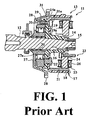
- FIG. 1 shows a prior art construction of this general type and is in part similar to those shown in US Patent 6, 534,880, assigned to the assignee hereof.
- an electric generator indicated generally at 11
- a rotor, indicated generally at 13. of the generator 11 includes a hub 14 fitted to a tapered end of the crankshaft portion 12 and is axially fixed thereto by a nut 14 threaded onto the crankshaft end 12.
- the rotor 13 is fixed against rotation relative to the crankshaft end 12 in a suitable manner, as by means of a key 16.
- the hub 14 has an integral flange section 14a at one axial end.
- the rotor 13 includes a generally cup shaped element, indicated generally at 17, having a cylindrical magnet holding portion 18 integrally formed at the outer periphery of an end wall 19.
- the end wall 19 has an opening 19a for passing the hub 14.
- a plurality of circumferentially spaced permanent magnets 21 are suitably fixed to the internal surface of the cylindrical portion 18.
- the rotor 13 and the hub 14 are integrally by means of plural (three, for example) rivets 22 disposed around the opening 19a in the end wall 19 of the rotor 13 and the flange section 14a of the hub 14.
- stator 23 for generating AC power upon the rotation of the rotor 13.
- the stator 23 is comprised of a laminated stator yoke 24 having an insulating bobbin 25 around which coils 26 are wound to generate an electromotive force upon the rotation of the rotor 13.
- flywheel 27 Positioned on the opposite side of the hub end wall 19 is a flywheel 27 having a starter gear 28 formed on its outer peripheral edge for cooperation with a starter motor (not shown).
- This flywheel 27 has a hub portion 27a that is journalled on the crankshaft portion 12 by an antifriction, needle bearing 30.
- the flywheel 27 is coupled to the crankshaft end portion 12 for engine starting by means of a one way clutch, indicated generally at 28.
- the one way clutch 28 is comprised of an outer race 29 that is affixed to the hub portion 14a by threaded fasteners 31 that have their heads 31a accessible through the interior of the rotor cylindrical portion 21 and which pass through openings formed in its integral flange section 14a. The threaded portions of the fasteners are received in tapped openings 31 formed in the outer race 29.
- the inner race of the one way clutch 28 is formed by the outer surface of the cylindrical hub portion 27a. Its roller members are received between these races, as is well known in the art.
- This invention is adapted to be embodied in an electrical generator for an internal combustion engine having an engine shaft.
- the generator is comprised of a hub portion adapted to be affixed for rotation with the engine shaft.
- a rotor portion is integrally formed with the hub portion and having a first, integral cylindrical portion extending in one axial direction therefrom for carrying a plurality of circumferentially spaced permanent magnets for cooperation with a stator.
- the hub portion further has a second, integral cylindrical portion extending in an axial direction opposite to the one axial direction for forming a race for a one way clutch for rotatably coupling a starter gear to the engine shaft.
- FIG. 1 is a cross sectional view taken through the rotational axis of a prior art type of generator for an internal combustion engine.
- FIG. 2 is a cross sectional view in part similar to FIG. 1 and shows a first embodiment of the invention.
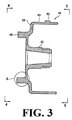
- FIG. 3 is an enlarged cross sectional view taken along the same plane as FIG. 2 but showing only the hub of the machine.
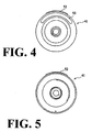
- FIG. 4 is an end elevational view of the hub looking in the direction of the arrows 4-4 in FIG. 3.
- FIG. 5 is an end elevational view of the hub looking in the direction of the arrows 5-5 in FIG. 3.
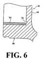
- FIG. 6 is an enlarged view of the area encompassed by the circle 6 in FIG. 3.
- FIG. 7 is an enlarged view, in part similar to FIG. 6 showing another embodiment.
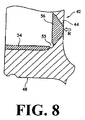
- FIG. 8 is an enlarged view, in part similar to FIGS. 6 and 7 to explain why the induction hardening can not be performed with a conventional induction hardening coil.
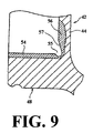
- FIG. 9 is an enlarged view, in part similar to FIGS. 6-8 and shows the desired induction hardening pattern.
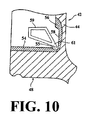
- FIG. 10 is an enlarged view, in part similar to FIGS. 6-9 and shows another embodiment and the desired induction hardening tool.
- FIG. 2 an electrical generator and associated internal combustion engine are shown in a view similar to FIG. 1. Since the main difference between the embodiments of the invention and the prior art lie in the construction of the magnet carrier or integral rotor, indicated in this embodiment generally by the reference numeral 41, where components or parts of components are of the same or substantially the same as the prior art construction previously described they are identified by the same reference numerals and will be described again only insofar as is necessary to permit those skilled in the art to understand and practice the invention.
- the rotor has an integral hub portion 42 that is fixed to the engine shaft 12 in any conventional manner as by a tapered opening, key 16, and threaded fastener 15.
- This integral hub portion 42 is unitary with a cylindrical magnet carrier portion 43 that carries on its inner cylindrical surface 43a the plurality of circumferentially spaced permanent magnets 21. These permanent magnets 21 cooperate with the stator assembly 23 in the same manner as in the prior art.
- the integral portions 42 and 43 are connected by a stepped end wall having slightly axially offset inner and outer portions 44 and 45, respectively.
- Rollers 46 of a one way clutch are held between an outer race forming portion 48 extending from the step formed between the portions 44 and 45 in the opposite axial direction from the magnet carrier portion 43.
- the rollers 46 are held axially in position by a retainer 49 and are carried by a roller carrier 51.
- the rotor 41 is generally constructed with the integral hub portion 42, the magnet carrier portion 43, and the clutch outer race forming portion 48.
- the outer surface of the magnet carrier portion 43 is formed with a thick-walled portion or projection 52 for detecting the rotational position of the rotor 41 that extends circumferentially over the predetermined angle range (for example 60 degrees). This cooperates with a sensor (not shown) for detecting the rotational positions of the rotor 41 or its rotational speed.
- a circumferential notch 53 is formed in the radially outer end wall portion 42b of the magnet carrier portion 43 for counterbalancing weight balance compensating for the thick-walled portion 52.
- the rotor only has a function for holding the magnets 21 functions as the integral hub portion 42 as well as the outer race forming portion 48 of the one-way clutch 47.
- those bolts and/or rivets previously required for connecting the several separate components can be eliminated.
- Their elimination also permits the diameter of the one-way clutch 28 can be reduced according with the reduction of the outer race forming portion diameter. Accordingly, the weight of the one-way clutch 28 can be reduced, its moment of inertia can be decreased, and the response at starting can be improved.
- the number of components can be reduced in comparison with conventional one-way clutches, and therefore the number of man-hours needed to assemble the generator can be reduced.
- the outer race forming portion 48 When the one way clutch 28 is engaged and disengaged, the outer race forming portion 48 receive force directed outward in the radial direction. Thus excessive force may act upon the clutch outer race forming portion 48 of the rotor 41 and the internal surface of the outer race forming portion 48 may wear due to the contact with the possibility that the durability of the rotor 41 decreased. Therefore, the internal surface (end surface) of the outer race forming portion 48 of the one-way clutch in the present embodiment is treated with induction hardening in order to improve its strength.
- an induction-hardened section 54 is formed over the area from a boundary between the flange section 44 of the integral hub portion 42 and an outer race forming portion end surface 43a along the internal surface of the outer race forming portion. Accordingly, the clutch outer race forming portion 48 can have the increased hardness than that of other portions and can ensure the durability of the rotor 41 itself even if it slidably contacts with the rollers 46 of the one way clutch 28.
- a notch 55 is formed during processing at the boundary part between the end surface of the clutch outer race forming portion 48 at the hardened portion 54 and the boss radially inner end wall portion 44 perpendicular to the hardened portion 54.
- the notch 55 also serves to avoid interference with a corner section of the roller holder 51 during the assembly of the clutch.
- FIG. 7 shows another embodiment of the induction-hardening treatment illustrated in FIG. 6.
- consideration is given to the possible occurrence of a crack due to residual stresses produced around the notch 55 as described above. That is to say, measures are taken here such that the range of the induction hardening is expanded to the radially inner end wall portion 44 of the integral hub portion 42 so as to decrease the residual stresses around the notch 55.
- the shape of the notch 55 itself is enlarged so as not to concentrate the stress in this section during the use of the clutch.
- thickness of the radially inner end wall portion 44 itself may be increased so as to increase the strength of the area around the notch 55.
- the integral-type rotor of the present invention is the type mounted to, for example, the crankshaft of an engine and requires heat resistance and high strength. Therefore, a material such as S48C containing carbon is used as the rotor material as an example.
- the end surface 43a of the clutch outer race forming portion is a receiving surface of a pin for the one-way clutch and requires additional high strength. Therefore, the outer race forming portion 48 is treated with the induction hardening 54 for increasing its strength.
- the induction hardening generally done with a high frequency coil (waveguide) made of a square pipe having a rectangular cross section and formed in a ring shape. This high frequency coil is applied to the hardened section and energized to heat the section.
- the notch 55 formed in the fillet by necessity in processing causes insufficient heating of the depths of the notch 55, resulting in a non-hardened part in the fillet. Therefore, as shown in FIG. 8, the hardened section 54 in the end surface 43a of the clutch outer race forming portion and a hardened section 56 in the radially inner end wall portion 44 become discontinuous at the notch 55, and a boundary of the hardened section is produced.
- the stress concentration produced in such hardening discontinuous part (hardening boundary) as well as the stress concentration based on the shape of the notch 55 act upon the fillet to cause the possibility that the fillet may crack.
- the radially inner end wall portion 44 may be melted and damaged.
- the thickness of the radially inner end wall portion 44 could be increased in order to prevent the melting because the weight of the radially inner end wall portion 44 would be increased resulting in increased rotation inertia of the rotor. Therefore other measures for preventing the melting damage should be employed. It is possible to cool the radially inner end wall portion 44 from the backside as shown by an arrow R. However, if the radially inner end wall portion is cooled the heating effect for the notch 55 is decreased and the induction hardening of the fillet cannot be achieved.
- the hardened area 56 is provided with a tapered surface 57 in the radially inner end wall portion 44 of the integral hub portion 42 in the rotor, communicating with the notch 55.
- the hardened section 56 in the radially inner end wall portion 44 is connected to the hardened section 54 in the outer race forming portion 48 the hardened section in the depths of the notch 55.
- FIG. 10 shows another shape of the hardened section and the type of hardening tool that can be employed to achieve the hardened shapes of FIGS. 9 and 10
- a specially formed high frequency coil 59 having a narrow tip 61 in the cross section is used for high-frequency heating.
- heat from the high frequency coil 59 is sufficiently transferred to the depths of the notch 55, the depths of the notch 55 is hardened and the hardened section 56 in the radially inner end wall portion 44 is connected to the hardened section 54 in the end surface of the clutch outer race forming portion 48 through the hardened section in the depths of the notch 55.
- induction-hardened sections are continuously formed in the fillet with the notch 55, and thus the stress concentration can be reduced and the possibility of crack production can be decreased.
- the high frequency coil 59 having the narrow tip 61 shown in the drawing is effectively used in the high-frequency heating for the example of FIG. 9 previously described.
- the high frequency coil 59 having a shape shown in FIG. 10 is not used and a normal high frequency coil having a rectangular cross section is used, as long as the width of the cross section of the coil is not more than the length of the stepped surface 58, sufficient high-frequency heating can be applied to the depths of the notch 55, and therefore, the depths of the notch 55 can be hardened.
- an electric generator for an internal combustion engine is constructed such that not only are the hub portion and the rotor integral, but also this integration extends to an element of the one-way clutch.
- those components which are separated in the prior art require only one unit.
- bolts and/or rivets required for connecting several components can be eliminated and the total number of components can be reduced.
- the diameter of the one-way clutch can be reduced and its weight can be reduced with a resulting decrease in the moment of inertia.
- the number of man-hours needed to assemble the unit can be reduced.
- a simplified electrical generator for an internal combustion engine in which the hub portion, magnet carrying portion and race for a one way clutch are all integrally formed to provide a more compact, lighter and lower cost assembly.
Landscapes
- Engineering & Computer Science (AREA)
- Power Engineering (AREA)
- General Engineering & Computer Science (AREA)
- Mechanical Engineering (AREA)
- Connection Of Motors, Electrical Generators, Mechanical Devices, And The Like (AREA)
- Permanent Magnet Type Synchronous Machine (AREA)
- Ignition Installations For Internal Combustion Engines (AREA)
Applications Claiming Priority (6)
| Application Number | Priority Date | Filing Date | Title |
|---|---|---|---|
| JP2003312490 | 2003-09-04 | ||
| JP2003312490 | 2003-09-04 | ||
| JP2004195433A JP4624016B2 (ja) | 2003-09-04 | 2004-07-01 | 内燃機関用発電機 |
| JP2004195433 | 2004-07-01 | ||
| US10/711,024 US20050052090A1 (en) | 2003-09-04 | 2004-08-18 | Electric generator for internal combustion engine |
| US711024 | 2004-08-18 |
Publications (3)
| Publication Number | Publication Date |
|---|---|
| EP1513245A2 true EP1513245A2 (fr) | 2005-03-09 |
| EP1513245A3 EP1513245A3 (fr) | 2006-03-22 |
| EP1513245B1 EP1513245B1 (fr) | 2010-06-16 |
Family
ID=34228020
Family Applications (1)
| Application Number | Title | Priority Date | Filing Date |
|---|---|---|---|
| EP04020929A Expired - Lifetime EP1513245B1 (fr) | 2003-09-04 | 2004-09-02 | Méthode de fabrication d'un générateur électrique pour un moteur à combustion interne |
Country Status (6)
| Country | Link |
|---|---|
| US (1) | US20050052090A1 (fr) |
| EP (1) | EP1513245B1 (fr) |
| JP (1) | JP4624016B2 (fr) |
| CN (1) | CN1599199A (fr) |
| DE (1) | DE602004027690D1 (fr) |
| TW (1) | TWI362811B (fr) |
Cited By (3)
| Publication number | Priority date | Publication date | Assignee | Title |
|---|---|---|---|---|
| CN102340211A (zh) * | 2010-07-21 | 2012-02-01 | 上海捷能汽车技术有限公司 | 一种集成于电机转子支架内的常开离合器和包括其的车辆 |
| CN102340210A (zh) * | 2010-07-21 | 2012-02-01 | 上海捷能汽车技术有限公司 | 一种集成于电机转子支架内的常闭离合器和包括其的车辆 |
| WO2019159198A1 (fr) * | 2018-02-16 | 2019-08-22 | India Nippon Electricals Ltd | Volant pour systèmes de magnéto-générateur |
Families Citing this family (6)
| Publication number | Priority date | Publication date | Assignee | Title |
|---|---|---|---|---|
| DE102009033178A1 (de) * | 2009-07-13 | 2011-01-27 | Licos Trucktec Gmbh | Elektromagnetische Reibschaltkupplung |
| DE102015113183B4 (de) | 2015-08-10 | 2018-06-28 | Yuan-Hung WEN | Über ein Kabel betätigte Antriebsanordnung für Fahrzeuge |
| DE102015017184B4 (de) | 2015-08-10 | 2020-02-13 | Yuan-Hung WEN | Über ein Kabel betätigte Antriebsanordnung für Fahrzeuge |
| CN108054868A (zh) * | 2018-01-29 | 2018-05-18 | 南京迪瓦机械制造有限公司 | 一种斗提机用永磁同步直驱电动机防逆转结构 |
| CN216130975U (zh) * | 2020-11-20 | 2022-03-25 | 浙江春风动力股份有限公司 | 一种机油泵齿轮及采用该齿轮的摩托车发动机 |
| US20230063544A1 (en) * | 2021-08-27 | 2023-03-02 | Minebea Mitsumi Inc. | Spindle motor and hard disk drive device |
Citations (1)
| Publication number | Priority date | Publication date | Assignee | Title |
|---|---|---|---|---|
| US20030085092A1 (en) | 2001-11-07 | 2003-05-08 | Musashi Seimitsu Kogyo Kabushiki Kaisha | One-way clutch |
Family Cites Families (12)
| Publication number | Priority date | Publication date | Assignee | Title |
|---|---|---|---|---|
| US3913863A (en) * | 1973-09-13 | 1975-10-21 | Hayes Albion Corp | Cast aluminum textile beam |
| JPS58131445A (ja) * | 1982-01-29 | 1983-08-05 | Honda Motor Co Ltd | 可変容量フライホイ−ル |
| JPS61149504A (ja) * | 1984-12-21 | 1986-07-08 | Nissan Motor Co Ltd | 空気機械の翼車構造 |
| US4735299A (en) * | 1985-03-29 | 1988-04-05 | Yamaha Hatsudoki Kabushiki Kaisha | One-way clutch and improved spring therefor |
| JPH0292489A (ja) * | 1988-09-30 | 1990-04-03 | Fuji Heavy Ind Ltd | センタレバーピンの高周波焼入れ方法 |
| JPH05148531A (ja) * | 1991-11-25 | 1993-06-15 | Toyota Motor Corp | フランジ付ワーク用高周波焼入装置 |
| JPH06344135A (ja) * | 1993-06-11 | 1994-12-20 | Taisei Corp | 柱と梁の溶接接合部 |
| DE69404782T2 (de) * | 1993-08-30 | 1997-12-04 | Honda Motor Co Ltd | Ölzufuhrkonstruktion für Anlassräder in einer Brennkraftmaschine |
| JP3154229B2 (ja) * | 1997-06-10 | 2001-04-09 | 株式会社久保田鉄工所 | 車両用部材の製造方法 |
| JP2001136694A (ja) * | 1999-11-08 | 2001-05-18 | Moriyama Manufacturing Co Ltd | 内燃機関用磁石発電機のロータ |
| JP4278844B2 (ja) * | 2000-08-08 | 2009-06-17 | Ntn株式会社 | クラッチユニット |
| JP3646989B2 (ja) * | 2001-12-05 | 2005-05-11 | 株式会社エクセディ | トルク伝達装置 |
-
2004
- 2004-07-01 JP JP2004195433A patent/JP4624016B2/ja not_active Expired - Fee Related
- 2004-08-18 US US10/711,024 patent/US20050052090A1/en not_active Abandoned
- 2004-08-31 TW TW093126283A patent/TWI362811B/zh not_active IP Right Cessation
- 2004-09-02 EP EP04020929A patent/EP1513245B1/fr not_active Expired - Lifetime
- 2004-09-02 DE DE602004027690T patent/DE602004027690D1/de not_active Expired - Lifetime
- 2004-09-03 CN CNA2004100769157A patent/CN1599199A/zh active Pending
Patent Citations (1)
| Publication number | Priority date | Publication date | Assignee | Title |
|---|---|---|---|---|
| US20030085092A1 (en) | 2001-11-07 | 2003-05-08 | Musashi Seimitsu Kogyo Kabushiki Kaisha | One-way clutch |
Cited By (5)
| Publication number | Priority date | Publication date | Assignee | Title |
|---|---|---|---|---|
| CN102340211A (zh) * | 2010-07-21 | 2012-02-01 | 上海捷能汽车技术有限公司 | 一种集成于电机转子支架内的常开离合器和包括其的车辆 |
| CN102340210A (zh) * | 2010-07-21 | 2012-02-01 | 上海捷能汽车技术有限公司 | 一种集成于电机转子支架内的常闭离合器和包括其的车辆 |
| CN102340210B (zh) * | 2010-07-21 | 2014-07-16 | 上海捷能汽车技术有限公司 | 一种集成于电机转子支架内的常闭离合器和包括其的车辆 |
| CN102340211B (zh) * | 2010-07-21 | 2014-07-16 | 上海捷能汽车技术有限公司 | 一种集成于电机转子支架内的常开离合器和包括其的车辆 |
| WO2019159198A1 (fr) * | 2018-02-16 | 2019-08-22 | India Nippon Electricals Ltd | Volant pour systèmes de magnéto-générateur |
Also Published As
| Publication number | Publication date |
|---|---|
| JP4624016B2 (ja) | 2011-02-02 |
| CN1599199A (zh) | 2005-03-23 |
| TW200522477A (en) | 2005-07-01 |
| TWI362811B (en) | 2012-04-21 |
| JP2005098288A (ja) | 2005-04-14 |
| DE602004027690D1 (de) | 2010-07-29 |
| EP1513245B1 (fr) | 2010-06-16 |
| EP1513245A3 (fr) | 2006-03-22 |
| US20050052090A1 (en) | 2005-03-10 |
Similar Documents
| Publication | Publication Date | Title |
|---|---|---|
| US5675202A (en) | Generator having pulley with one-way clutch | |
| US7834512B2 (en) | Automotive alternator including annular core having protrusions and recesses alternately formed on its outer surface | |
| US6204577B1 (en) | Method and apparatus for space-saving installation of a starter-alternator | |
| JP4396471B2 (ja) | 車両用回転電機およびその製造方法 | |
| US6424065B1 (en) | Starter-generator for a motor vehicle | |
| EP1513245B1 (fr) | Méthode de fabrication d'un générateur électrique pour un moteur à combustion interne | |
| JP3480122B2 (ja) | 発電機 | |
| JPH10122107A (ja) | エンジンのスタータ装置 | |
| US20050119077A1 (en) | Assembly and method of assembling a motor vehicle alternator pulley and a motor vehicle alternator comprising one such assembly | |
| US11788534B2 (en) | Automotive accessory using a magnetic field between circumferentially spaced teeth, a rotor body and a pulley to create a secondary torque path | |
| US6796413B2 (en) | One-way clutch | |
| US20050127768A1 (en) | Rotor for an electrical machine | |
| US11336148B2 (en) | Pulley assisted electromagnetic fluid pump | |
| JP2019510933A (ja) | 動力伝達組立体のための電磁ブレーキ | |
| JP7214577B2 (ja) | 始動発電機及び始動発電機の製造方法 | |
| US7714468B2 (en) | Magnetoelectric generator | |
| US10578190B2 (en) | Drivetrain module for a motor vehicle | |
| CN114206653B (zh) | 带轮辅助的电磁水泵 | |
| US6484389B1 (en) | Apparatus for pilotless self-centering installation of a starter-alternator | |
| US11791699B2 (en) | Rotor arrangement | |
| JP4168435B2 (ja) | 発電機 | |
| JP2007309209A (ja) | エンジンの始動装置 | |
| JP2009022132A (ja) | 回転電機 | |
| JP2005218254A (ja) | 一方向クラッチ及び発電機用アウタロータの組立体 | |
| JP2743817B2 (ja) | フライホイール磁石回転子の製造方法 |
Legal Events
| Date | Code | Title | Description |
|---|---|---|---|
| PUAI | Public reference made under article 153(3) epc to a published international application that has entered the european phase |
Free format text: ORIGINAL CODE: 0009012 |
|
| AK | Designated contracting states |
Kind code of ref document: A2 Designated state(s): AT BE BG CH CY CZ DE DK EE ES FI FR GB GR HU IE IT LI LU MC NL PL PT RO SE SI SK TR |
|
| AX | Request for extension of the european patent |
Extension state: AL HR LT LV MK |
|
| PUAL | Search report despatched |
Free format text: ORIGINAL CODE: 0009013 |
|
| AK | Designated contracting states |
Kind code of ref document: A3 Designated state(s): AT BE BG CH CY CZ DE DK EE ES FI FR GB GR HU IE IT LI LU MC NL PL PT RO SE SI SK TR |
|
| AX | Request for extension of the european patent |
Extension state: AL HR LT LV MK |
|
| 17P | Request for examination filed |
Effective date: 20060830 |
|
| AKX | Designation fees paid |
Designated state(s): DE FR IT |
|
| 17Q | First examination report despatched |
Effective date: 20070824 |
|
| RAP1 | Party data changed (applicant data changed or rights of an application transferred) |
Owner name: YAMAHA MOTOR ELECTRONICS KABUSHIKI KAISHA |
|
| GRAP | Despatch of communication of intention to grant a patent |
Free format text: ORIGINAL CODE: EPIDOSNIGR1 |
|
| RTI1 | Title (correction) |
Free format text: METHOD FOR MANUFACTURING AN ELECTRIC GENERATOR FOR INTERNAL COMBUSTION ENGINE |
|
| GRAS | Grant fee paid |
Free format text: ORIGINAL CODE: EPIDOSNIGR3 |
|
| GRAA | (expected) grant |
Free format text: ORIGINAL CODE: 0009210 |
|
| AK | Designated contracting states |
Kind code of ref document: B1 Designated state(s): DE FR IT |
|
| REF | Corresponds to: |
Ref document number: 602004027690 Country of ref document: DE Date of ref document: 20100729 Kind code of ref document: P |
|
| PG25 | Lapsed in a contracting state [announced via postgrant information from national office to epo] |
Ref country code: IT Free format text: LAPSE BECAUSE OF FAILURE TO SUBMIT A TRANSLATION OF THE DESCRIPTION OR TO PAY THE FEE WITHIN THE PRESCRIBED TIME-LIMIT Effective date: 20100616 |
|
| PLBE | No opposition filed within time limit |
Free format text: ORIGINAL CODE: 0009261 |
|
| STAA | Information on the status of an ep patent application or granted ep patent |
Free format text: STATUS: NO OPPOSITION FILED WITHIN TIME LIMIT |
|
| 26N | No opposition filed |
Effective date: 20110317 |
|
| REG | Reference to a national code |
Ref country code: FR Ref legal event code: ST Effective date: 20110531 |
|
| REG | Reference to a national code |
Ref country code: DE Ref legal event code: R097 Ref document number: 602004027690 Country of ref document: DE Effective date: 20110316 |
|
| PG25 | Lapsed in a contracting state [announced via postgrant information from national office to epo] |
Ref country code: FR Free format text: LAPSE BECAUSE OF NON-PAYMENT OF DUE FEES Effective date: 20100930 |
|
| PGFP | Annual fee paid to national office [announced via postgrant information from national office to epo] |
Ref country code: DE Payment date: 20210920 Year of fee payment: 18 |
|
| REG | Reference to a national code |
Ref country code: DE Ref legal event code: R119 Ref document number: 602004027690 Country of ref document: DE |
|
| PG25 | Lapsed in a contracting state [announced via postgrant information from national office to epo] |
Ref country code: DE Free format text: LAPSE BECAUSE OF NON-PAYMENT OF DUE FEES Effective date: 20230401 |