EP1514342B1 - Procede et ensemble de circuits pour faire fonctionner des moteurs pas a pas - Google Patents
Procede et ensemble de circuits pour faire fonctionner des moteurs pas a pas Download PDFInfo
- Publication number
- EP1514342B1 EP1514342B1 EP03757042A EP03757042A EP1514342B1 EP 1514342 B1 EP1514342 B1 EP 1514342B1 EP 03757042 A EP03757042 A EP 03757042A EP 03757042 A EP03757042 A EP 03757042A EP 1514342 B1 EP1514342 B1 EP 1514342B1
- Authority
- EP
- European Patent Office
- Prior art keywords
- coil
- emk
- measuring
- motor
- current
- Prior art date
- Legal status (The legal status is an assumption and is not a legal conclusion. Google has not performed a legal analysis and makes no representation as to the accuracy of the status listed.)
- Expired - Lifetime
Links
- 238000000034 method Methods 0.000 title claims abstract description 16
- 238000004590 computer program Methods 0.000 claims 2
- 230000001360 synchronised effect Effects 0.000 abstract description 4
- 238000005259 measurement Methods 0.000 description 11
- 230000010363 phase shift Effects 0.000 description 11
- 238000010586 diagram Methods 0.000 description 10
- 238000001514 detection method Methods 0.000 description 5
- 230000007423 decrease Effects 0.000 description 4
- 230000033001 locomotion Effects 0.000 description 3
- 238000012544 monitoring process Methods 0.000 description 3
- 238000004804 winding Methods 0.000 description 3
- 230000001419 dependent effect Effects 0.000 description 2
- 238000013461 design Methods 0.000 description 2
- 238000011161 development Methods 0.000 description 2
- 230000018109 developmental process Effects 0.000 description 2
- 238000011156 evaluation Methods 0.000 description 2
- 230000001133 acceleration Effects 0.000 description 1
- 238000013459 approach Methods 0.000 description 1
- 230000002238 attenuated effect Effects 0.000 description 1
- 230000033228 biological regulation Effects 0.000 description 1
- 230000001276 controlling effect Effects 0.000 description 1
- 230000007613 environmental effect Effects 0.000 description 1
- 230000004907 flux Effects 0.000 description 1
- 230000006698 induction Effects 0.000 description 1
- 230000010354 integration Effects 0.000 description 1
- 230000005415 magnetization Effects 0.000 description 1
- 230000000737 periodic effect Effects 0.000 description 1
- 238000012545 processing Methods 0.000 description 1
- 230000002250 progressing effect Effects 0.000 description 1
- 230000001105 regulatory effect Effects 0.000 description 1
Images
Classifications
-
- H—ELECTRICITY
- H02—GENERATION; CONVERSION OR DISTRIBUTION OF ELECTRIC POWER
- H02P—CONTROL OR REGULATION OF ELECTRIC MOTORS, ELECTRIC GENERATORS OR DYNAMO-ELECTRIC CONVERTERS; CONTROLLING TRANSFORMERS, REACTORS OR CHOKE COILS
- H02P6/00—Arrangements for controlling synchronous motors or other dynamo-electric motors using electronic commutation dependent on the rotor position; Electronic commutators therefor
- H02P6/006—Controlling linear motors
-
- H—ELECTRICITY
- H02—GENERATION; CONVERSION OR DISTRIBUTION OF ELECTRIC POWER
- H02P—CONTROL OR REGULATION OF ELECTRIC MOTORS, ELECTRIC GENERATORS OR DYNAMO-ELECTRIC CONVERTERS; CONTROLLING TRANSFORMERS, REACTORS OR CHOKE COILS
- H02P6/00—Arrangements for controlling synchronous motors or other dynamo-electric motors using electronic commutation dependent on the rotor position; Electronic commutators therefor
- H02P6/14—Electronic commutators
- H02P6/16—Circuit arrangements for detecting position
- H02P6/18—Circuit arrangements for detecting position without separate position detecting elements
- H02P6/182—Circuit arrangements for detecting position without separate position detecting elements using back-emf in windings
-
- H—ELECTRICITY
- H02—GENERATION; CONVERSION OR DISTRIBUTION OF ELECTRIC POWER
- H02P—CONTROL OR REGULATION OF ELECTRIC MOTORS, ELECTRIC GENERATORS OR DYNAMO-ELECTRIC CONVERTERS; CONTROLLING TRANSFORMERS, REACTORS OR CHOKE COILS
- H02P8/00—Arrangements for controlling dynamo-electric motors rotating step by step
- H02P8/32—Reducing overshoot or oscillation, e.g. damping
Definitions
- the invention relates to a method and a circuit arrangement for operating stepper motors or other suitably dimensioned synchronous motors.
- Stepper motors are known to be precisely controlled to move and position controlled.
- the rotational position of a magnetic rotor follows a magnetic field which is generated by phase-shifted energization of a plurality of coils which are arranged around the rotor. If a stepper motor is to serve not only for the relative, but also for the absolute positioning of an object, it is first necessary to determine a reference position to which the absolute position can be referred. A controlled absolute positioning is then possible as long as the control of the stepping motor takes place taking into account its characteristic motion parameters such as rotation angle, speed and acceleration.
- a reference position essentially two alternatives are known. These are on the one hand, the mechanical homing, in which the motor is driven against a mechanical, serving as a reference position limit or stop, and on the other the electrical reference travel, in which a sensor (for example, an electromechanical switch or a photoelectric sensor) upon reaching a Reference position generates a corresponding signal.
- a sensor for example, an electromechanical switch or a photoelectric sensor
- step losses may occur due to certain operating states such as suddenly occurring load changes due to obstacles or the like during operation of a stepper motor, or the stepper motor may even stop, so that a new reference run becomes necessary.
- a reference run during operation is not possible, so that in addition to the single determination of the reference position, a monitoring of the operating state of the stepping motor during operation - but especially without additional sensors - is desirable.
- a method of driving rotary detector circuitry which determines whether a drive pulse being fed to a stepper motor causes the rotor to rotate in the correct direction.
- the rotation detection essentially takes place in that an element of high or low impedance is electrically connected to a winding of the motor when a first or second switching device is being retracted and that first, second and third signals are fed to the first and second switching device in order to feed the element to separate low impedance from the winding while the high impedance element is connected to the winding at the time of rotation detection.
- a method for controlling a voltage / frequency converter controlled single or polyphase electric motor is known, with which a phase shift between an EMF voltage and a BEMF voltage is determined from the deviation between the zero crossing of the phase current and the voltage generated by self-induction and the frequency the converter is readjusted accordingly.
- the measurement of the self-induction takes place at the zero crossing of the current profile of the associated phase, during which the phase is disconnected from the supply network.
- the invention is based on the general object to provide a method and a circuit arrangement for operating a stepping motor (or another suitably dimensioned synchronous motor), with the / in a simple way, a load detection and thus a determination of a reference position of the motor is possible.
- This object is achieved according to claim 1 with a method for operating stepper motors with a first mode for a normal engine operation, in which an alternating current is impressed in at least one of the coils of the stepping motor, and a second mode for determining a reference position of the stepping motor based on a by driving the stepping motor against a mechanical stop caused increase in load, by comparing the height of a current flowing in the coil measuring current with at least a lower threshold, wherein the height of the measuring current is determined essentially by the phase of a by a rotor of the motor in the coil against induced voltage, and wherein the reference position is defined when the measurement current becomes less than the lower threshold, and wherein the second mode for the coil is activated within a time window of the first mode either by shorting the coil when the AC current impressed in the coil approaches a zero crossing, or the direction of the AC current injected into the coil is reversed.
- the object is further achieved by a circuit arrangement for operating a stepping motor according to claim 6.
- a general advantage of these solutions is that no sensors are required and a relatively simple and inexpensive implementation is possible, especially when the motor is driven by pulse width modulation (PWM) of a voltage that impresses a corresponding current in the motor coils (coil current) the components required for evaluating the measuring current (short-circuit current) are already largely present in a PWM circuit.
- PWM pulse width modulation
- the background is the fact that with increasing motor load and thus increasing load angle (angle between the rotor and the main direction of the magnetic field generated by the coils), the phase shift between the coil current impressed into the coil and the voltage counteracted by the rotor becomes smaller (and at standing engine is zero).
- the magnitude of the measuring current (current lobe) at constant speed directly represents the magnitude of the torque of the engine load and, together with the torque characteristic of the engine concerned indirectly the load angle.
- a reference position of the motor can be detected sensorless.
- the disadvantages associated with a conventional sensorless determination of a reference position such as mechanical wear and noise development, do not occur or only to a significantly lesser extent.
- An advantage of the above-described almost direct load or torque measurement in the (mechanical) reference run is that it is largely independent of the modulus of elasticity of the mechanical stop.
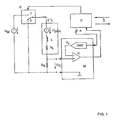
- Figure 1 shows a schematic diagram of a circuit arrangement, which can be switched with a switch S between a first mode for normal engine operation (switch position 1) and a second mode for detecting an operating condition and in particular a reference position of the engine (switch position 0) by measuring a mechanical load change is determined when driving the stepper motor against a mechanical stop.
- the stepping motor itself is shown only in the form of one of its coils L with a serial internal resistance R L , a plurality of these coils being arranged in a known manner in a circle around a magnetic rotor. Alternatively, however, it may also be a linear stepper motor.
- a voltage source for generating a supply voltage U M (PWM voltage) connected to the in the first mode a specific target current (coil current) I L in the (b) coil ( n) L is impressed.
- a measuring resistor R S In series with each coil L is also a measuring resistor R S , at which a measuring voltage U S in dependence on an actually flowing through the coil L (measuring) current drops.
- such a stepper motor driver operates at a sufficiently high supply voltage as a quasi-ideal power source, provided that the power reduction takes place not only passive (“slow decay”), but active (“fast decay”).
- the circuit arrangement further comprises a measuring circuit M, at the input of which the measuring voltage U S is present and which has a comparator K for comparing the measuring voltage U S with a reference voltage U R , and a digital / analog converter DAC for generating the comparison voltage from one of the measuring circuit M digital signal.
- the comparison voltage U R can also be supplied in a different manner or in analog form.
- control circuit C which generates the digital signal for the digital / analog converter DAC and the output signal of the comparator K is supplied.
- the control circuit C can be controlled via an interface I in order to switch the switch S between its two switch positions 0 and 1 as a function of the output signal of the comparator K or to provide this output signal for further processing.
- the measuring circuit M and the control circuit C are in the case of a pulse width modulation (PWM) controlled coil current I L in general already present, so that the circuit arrangement according to the invention can be implemented inexpensively and with relatively little additional effort.
- PWM pulse width modulation
- the coils L are phase-shifted with alternating currents fed so that in a known manner, a magnetic field is progressing, the magnetic rotor follows stepwise or quasi-continuously in microsteps.
- the measuring voltage U S dropped across the measuring resistor R S can be evaluated and used in a known manner to control or regulate the voltage source generating the supply voltage U M.
- an electric voltage U EMK is induced in the coil L, counteracting the supply voltage U M and with respect to its course substantially relative to the speed of the rotor and its instantaneous position the coil is dependent.
- this voltage is represented by a voltage source connected in series with the coil L, which generates the voltage U EMK .
- the voltage U L over the terminals of the coil L with respect to the impressed coil current I L is phase-shifted by 90 ° (ie at an active power of zero). The average power over a period is then equal to zero. With increasing load angle, this phase shift between the voltage U L and the coil current decreases I L. At maximum load angle (ie, just before a step loss), the phase shift is ultimately essentially zero and the power is maximum.
- the counter-induced voltages U EMK are ideally also sinusoidal and cosinusoidal and opposite the coil currents I L in the respective coils L by 90 ° in phase postponed.
- phase shifts of a constant nature and other characteristics of the voltages U EMK can be caused by the design of the motor and in particular the geometric shape of the rotor and the stator and their magnetization.
- stepper motor may jump one or more integer multiples of the current period (four full steps in a 2-phase stepper motor) and thus lose steps.
- a phase shift also occurs between the coil current I L and the counter-induced voltage U EMK , whereby the course of the voltage U EMK can also change considerably due to the jumps.
- the phase of the counter-induced voltage U EMK thus essentially represents the rotor position.
- the time course of the target current I L through the coils L is not necessarily sinusoidal and cosinusoidal. Depending on the type of stepper motor, better running behavior can be achieved with trapezoidal or triangular current patterns or hybrid forms thereof.
- the counter-induced voltage U EMK is in principle nevertheless suitable for determining the above-described movement and load states of the stepping motor, ie its operating state, and thus also for detecting a mechanical stop, for example at a reference position. since the height of the voltage U EMK and the phase position to the coil current I L in addition to the speed of the rotor in particular depends on the load angle of the rotor and thus the load condition of the motor.
- the amplitude of the counter-induced voltage U EMK is proportional to the speed of the rotor.
- the phase of this voltage U EMK relative to the impressed coil current I L is essentially determined by the mechanical load. At a maximum possible load, this phase shift decreases substantially to the value 0. This is clear from Figures 2 to 4 and will be explained in more detail later.
- the voltage U EMK could be measured with a non-energized coil L directly above the terminals of the coil. However, since such a coil L makes no contribution to the torque of the motor, this type of detection is not desirable. Also, a quick change between energized and non-energized state is not desirable due to the occurring, relatively high induction voltages.
- the counter-induced voltage U EMK in the second operating mode is determined by disconnecting the coil from the supply voltage U M and short-circuiting the coil, in each case periodically within such time windows in which the impressed current I L in the relevant coil L relatively low is, that is shortly before and after the polarity change of this current or the supply voltage U M impressing on it .
- the switch S is switched to the switch position 0.
- the beginning of the time window need not be determined by monitoring the measurement voltage U S and comparison with a comparison voltage. Rather, the beginning and the length of the time window is given by the known or fixed profile of the supply voltage U M or the course of the injected into the coil in question I L , so that the control circuit C for switching the switch S directly via the interface I can be controlled accordingly.
- the counter-induced voltage U EMK drives in the thus shorted coil circuit now a measuring current I S, EMK (current lobe), which generates a corresponding voltage drop U S, EMK on the measuring resistor R S.
- This voltage U S, EMK is in turn evaluated by the measuring circuit M to determine the operating condition of the motor and to determine whether the motor is running under a more or less high mechanical load or even against a mechanical stop, to avoid wear if necessary switch off immediately.
- the voltage U S, EMK in the comparator K is compared with different threshold values U SO , U SU , which are determined as a function of the rotational speed of the motor and as digital values via the interface I and the control circuit C to the digital / analog converter DAC (or also analog) are supplied.
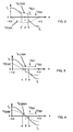
- the vertical axis denotes the height of the current or the voltage, while the period is plotted on the horizontal axis.
- This coil current I L is within the time window Z, in which the coil circuit is shorted by switching the switch S in the switch position 0, zero. Instead, flows within the time window Z substantially caused by the counter-induced voltage U EMK measuring current I S, EMK (shown in dashed lines, current lobes), through which a measuring voltage U S, EMK decreases at the measuring resistor R S.
- FIG. 2 shows the courses of these currents and voltages for a substantially unloaded state, that is to say at a minimum load angle
- FIG. 3 shows the courses at an average load and a mean load angle
- FIG. 4 shows the curves of the currents and voltages at a maximum load and a maximum load angle.
- phase shift decreases with increasing load between the coil current I L or - during the second mode - between the measuring current I S, EMK through the coil L and the counter-induced voltage U EMK .
- the counter-induced voltage U EMK behaves in phase opposition to the supply voltage U M with respect to its polarity.
- the magnitude of the measuring current I S, EMF (current lobe) flowing within the time window Z and thus the height of the measuring voltage U S, EMK generated by the latter within the time window Z depends on the rotational speed and the load angle of the motor caused by a load and thus represents also the recorded active power.
- a load change leads to a phase shift of the counter-induced voltage U EMK and thus to a change in the current driven by this in the coil circuit current. This change in turn results in a change of the measuring current I S, EMF (current lobe) flowing within the time window Z, which is detected by evaluation of the measuring voltage U S, EMK .
- a change in the load of the motor can be detected.
- Load changes are preferably detected by a comparison of the measuring voltage U S, EMK within the time window Z with threshold values, which are determined as a function of the speed of the motor.
- an upper and a lower threshold value U SO , U SU for the measuring voltage U S, EMK are set such that the measuring voltage U S, EMK is greater at a certain speed and relatively low load of the motor , as the upper threshold U SO , while at a mechanical load increase, which is caused by driving against a mechanical stop, the measuring voltage U S, EMK is below the lower threshold U SU .
- Figure 2 shows the case in which within the time window Z, a measuring current I S, EMK flows through the coil, through which a measuring voltage U S, EMK is generated, which corresponds to the upper threshold U SO .
- a measuring current I S, EMF flows through the coil, through which a measuring voltage U S, EMK which corresponds to the lower threshold value U SU drops.
- the load is so great that the measuring current I S, EMF and thus also the voltage drop U S, EMK is substantially zero.
- the measurement voltage U S, EMK is thus compared with the two threshold values U SO , U SU within a time window Z, the measurement voltage being applied to one input of the comparator K and one threshold value to the other input of the comparator K.
- the threshold values U SO , U SU are supplied via the interface I and the control circuit C to the digital / analog converter DAC.
- the internal resistance R L of the relevant coil L is of the order of the measuring resistor R S , so that the measuring voltage U S, EMK in the load measurement sufficiently large, that is in the range of the measuring voltage U S. in normal operation. If a switchable measuring resistor R S is provided, the solution according to the invention can also be applied to high-impedance motors. If, on the other hand, R L >> R S is, then the measuring circuit M should have a sufficiently high gain.
- the measuring voltage U S, EMK is independent of the supply voltage U M , since it is detected during a time window in which the supply voltage (PWM) is not present.
- the current loop resulting from the short-circuiting of the coil circuit is low-resistance, so that the measuring voltage U S, EMK is relatively insensitive to interference.
- the measuring resistor R S causes a current limitation with a short-circuited coil circuit.
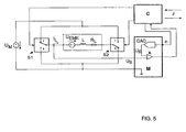
- FIG. 5 shows a block diagram of a second circuit arrangement according to the invention, in which the same or corresponding components as in FIG. 1 are provided with the same designations.
- the PWM supply voltage U M can be reversed by means of a first and a second switch S1, S2, which are switched by the control circuit C.
- the second operating mode during which the measured current I S, EMK generated by the region-induced voltage U EMK is detected and evaluated according to the above explanation, in this case becomes immediately after the polarity reversal of the PWM supply voltage, ie immediately after the switching of the two switches S1 , S2 activated, whereby previously the measuring current must not be regulated out (slow-decay mode).
- the measuring voltage conducted to the comparator does not necessarily have to be generated by a voltage drop by means of a resistor R S. Rather, it is also possible to use Hall sensors, current dividers in MOSFET switches or other elements, if appropriate at other locations of the circuit arrangement, with which a signal proportional to the measuring current through the coil L is generated, which signal corresponds to the corresponding signal Thresholds can be compared.
- phase shift and the amplitude reduction of the periodic coil current I L are very sensitive to a load change, but both sizes are very insensitive to other disturbances that are not related to it, such as the irradiation of electrical energy. As a result, a very accurate detection of even small load changes is possible.
- the coil in the coil circuit smoothes any electrical interference, so that their influence is further reduced.
- the measurement conditions are very well defined within the time window Z and thus very well reproducible.
- the current I S, EMK flowing within the time window Z only depends on the rotational speed of the motor, the load angle and motor constants, but does not or only very slightly depends on parameters that drift or vary due to specimen scattering.
- inventive method and the circuit arrangement according to the invention is also suitable for use with other synchronous motors, provided that they are dimensioned such that at least one of the coil circuits can be short-circuited.
Landscapes
- Engineering & Computer Science (AREA)
- Power Engineering (AREA)
- Control Of Stepping Motors (AREA)
Claims (10)
- Procédé pour faire fonctionner le un moteur pas-à-pas,
comprenant un premier mode de fonctionnement pour le fonctionnement normal d'un moteur dans lequel un courant alternatif (IL) est appliqué sur au moins une des bobines (L) du moteur pas-à-pas, et un deuxième mode de fonctionnement pour la détermination d'une position de référence du moteur pas-à-pas sur la base d'une augmentation de la charge provoquée par l'entrainement du moteur pas-à-pas contre un arrêt mécanique, en comparant le niveau d'un courant de mesure (IS,EMK) qui circule dans la bobine (L), avec au moins une valeur de seuil plus faible; le niveau du courant de mesure (IS,EMK) étant essentiellement déterminé par la phase d'une tension (UEMK) qui est contre-induite par un rotor d'un moteur dans la bobine (L), et où la position de référence est réglée et définie, respectivement, lorsque le courant de mesure (IS,EMK) est inférieur à la valeur de seuil plus faible, et où le deuxième mode de fonctionnement pour la bobine (L) est activé pendant une fenêtre de temps (Z) du premier mode de fonctionnement, soit en court-circuitant la bobine (L) lorsque le courant alternatif (IL) appliqué sur la bobine (L) se rapproche du passage par zéro, ou lorsque la direction du courant alternatif (IL) appliqué sur la bobine est inversée. - Procédé selon la revendication 1,
dans lequel le niveau du courant de mesure (IS,EMK) circulant à travers la bobine (L) pendant le deuxième mode de fonctionnement, est comparé avec au moins une valeur de seuil supérieure qui est fixée en liaison avec la vitesse du moteur, laquelle valeur de seuil supérieure est plus élevée que la valeur de seuil plus faible afin de détecter un état de charge faible du moteur lorsque le courant de mesure (IS,EMK) est plus élevé que la valeur de seuil supérieure. - Procédé selon la revendication 1,
dans lequel la valeur de seuil plus faible est fixée en liaison avec la vitesse du moteur afin de détecter un état de charge élevée, lorsque le courant de mesure (IS,EMK) est inférieur à la valeur de seuil plus faible. - Procédé selon la revendication 1,
dans lequel la fenêtre de temps (Z) pour le deuxième mode de fonctionnement est incorporé dans le premier mode de fonctionnement pour être positionnée essentiellement de manière symétrique à un passage à zéro du courant alternatif (IL) appliqué sur la bobine (L) concernée pendant le premier mode de fonctionnement. - Procédé selon la revendication 1 ou 2,
dans lequel le niveau du courant de mesure (IS,EMK) circulant à travers la bobine (L) court-circuitée, est détecté par une chute de tension (US,EMK) sur une résistance de mesure (RS) et lequel courant de mesure est comparé avec les valeurs de seuil sous la forme de tensions (USO, USU). - Ensemble de circuits pour faire fonctionner un moteur pas-à-pas,
notamment selon un procédé conforme à une des revendications précédentes, comprenant un dispositif (S; M, RS; C) pour la détermination d'une position de référence du moteur pas-à-pas sur la base d'une augmentation de la charge provoquée par l'entrainement du moteur pas-à-pas contre un arrêt mécanique à l'aide d'un circuit de mesure (M) destiné à comparer le niveau d'un courant de mesure (IS,EMK) circulant dans une bobine (L) du moteur; le niveau étant déterminé essentiellement par la phase d'une tension (UEMK) qui est contre-induite par un rotor du moteur dans la bobine (L), avec au moins une valeur de seuil inférieure, lorsque le courant alternatif (IL) appliqué sur la bobine (L) pendant le mode de fonctionnement normal s'approche du passage à zéro et que la bobine (L) est court-circuitée, ou lorsque la direction du courant alternatif (IL) est inversée. - Ensemble de circuits selon la revendication 6,
dans lequel le dispositif (S; M, RS; C) comprend une résistance de mesure (RS), et dans lequel le circuit de mesure (M) comprend un comparateur (K) destiné à comparer une tension de mesure (US,EMK) qui a chuté à la résistance de mesure (RS) par le courant de mesure (IS,EMK) avec au moins une valeur de seuil (USU) plus faible. - Disposition en circuit selon la revendication 7,
dans lequel le dispositif (S; M, RS; C) comprend un circuit de contrôle (C), et dans lequel le circuit de mesure (M) comprend un convertisseur numérique-analogique (CNA) avec une entrée reliée à une sortie du circuit de contrôle (C), et avec une sortie reliée à une entrée du comparateur (K) afin d'appliquer au moins une valeur de seuil plus faible ou supérieure (USU, USO); où les valeurs de seuil sont fixées en liaison avec la vitesse de rotation du moteur et fournies par le circuit de contrôle (C) afin de détecter un état de fonctionnement et de charge, respectivement, en comparant la tension de mesure (US,EMK) avec les valeurs de seuil. - Ensemble de circuits selon la revendication 8,
dans lequel on a prévu le circuit de contrôle (C) pour contrôler un commutateur (S) destiné à commuter entre le premier et le deuxième mode de fonctionnement en liaison avec la fréquence du courant alternatif (IL) appliqué sur la bobine. - Un programme informatique comprenant des moyens de code de programmes d'ordinateur destinés à conduire un procédé selon une des revendications 1 à 5, lorsque le programme est lancé sur un micro-ordinateur.
Applications Claiming Priority (3)
| Application Number | Priority Date | Filing Date | Title |
|---|---|---|---|
| DE10225610 | 2002-06-07 | ||
| DE10225610A DE10225610B4 (de) | 2002-06-07 | 2002-06-07 | Verfahren und Schaltungsanordnung zum Betreiben eines Schrittmotors |
| PCT/EP2003/006019 WO2003105332A1 (fr) | 2002-06-07 | 2003-06-07 | Procede et ensemble de circuits pour faire fonctionner des moteurs pas a pas |
Publications (2)
| Publication Number | Publication Date |
|---|---|
| EP1514342A1 EP1514342A1 (fr) | 2005-03-16 |
| EP1514342B1 true EP1514342B1 (fr) | 2007-11-14 |
Family
ID=29718914
Family Applications (1)
| Application Number | Title | Priority Date | Filing Date |
|---|---|---|---|
| EP03757042A Expired - Lifetime EP1514342B1 (fr) | 2002-06-07 | 2003-06-07 | Procede et ensemble de circuits pour faire fonctionner des moteurs pas a pas |
Country Status (6)
| Country | Link |
|---|---|
| US (1) | US7301300B2 (fr) |
| EP (1) | EP1514342B1 (fr) |
| AT (1) | ATE378725T1 (fr) |
| AU (1) | AU2003250826A1 (fr) |
| DE (2) | DE10225610B4 (fr) |
| WO (1) | WO2003105332A1 (fr) |
Cited By (3)
| Publication number | Priority date | Publication date | Assignee | Title |
|---|---|---|---|---|
| DE102011000569A1 (de) * | 2010-11-09 | 2012-05-10 | Trinamic Motion Control Gmbh & Co. Kg | Verfahren und Schaltungsanordnung zur sensorlosen Motorlasterfassung und zur lastwertabhängigen Motorstromregelung bei einem Schrittmotor |
| US9112439B2 (en) | 2010-11-09 | 2015-08-18 | Trinamic Motion Control Gmbh & Co. Kg | Method and circuit arrangement for detecting motor load without sensors and for controlling motor current according to load for a stepper motor |
| DE102018126954A1 (de) * | 2018-10-29 | 2020-04-30 | Trinamic Motion Control Gmbh & Co. Kg | Verfahren und Schaltungsanordnung zur sensorlosen Lasterfassung bei Schrittmotoren |
Families Citing this family (14)
| Publication number | Priority date | Publication date | Assignee | Title |
|---|---|---|---|---|
| RU2377715C2 (ru) * | 2004-09-17 | 2009-12-27 | Эйрбас Дойчланд Гмбх | Схема и способ определения режима работы электродвигателя и их применение |
| JP5011111B2 (ja) | 2004-09-17 | 2012-08-29 | エアバス オペレーションズ ゲーエムベーハー | カウンター電子運動力に基づいた、電気モータの機能状態検出 |
| US7239108B2 (en) * | 2005-01-31 | 2007-07-03 | Texas Instruments Incorporated | Method for stepper motor position referencing |
| DE102006020966A1 (de) * | 2006-05-05 | 2007-11-08 | Kostal Industrie Elektrik Gmbh | Verfahren und Vorrichtung zur Erkennung eines Blockierzustands bei einem Synchron- oder Schrittmotor |
| US7439701B2 (en) | 2006-06-26 | 2008-10-21 | Yazaki Corporation | Method and device for detecting initial excitation phase of stepping motor |
| DE102006035023A1 (de) * | 2006-07-28 | 2008-01-31 | Yazaki Corp. | Verfahren und Vorrichtung zum Detektieren der Anfangserregerphase eines Schrittmotors |
| DE102007041299A1 (de) * | 2007-08-31 | 2009-03-05 | BSH Bosch und Siemens Hausgeräte GmbH | Verfahren zum Betreiben einer Geschirrspülmaschine |
| WO2010130802A2 (fr) * | 2009-05-13 | 2010-11-18 | Elmos Semiconductor Ag | Procédé d'identification du blocage de moteurs électriques à commutation électrique |
| US8823301B2 (en) | 2012-11-05 | 2014-09-02 | Whirlpool Corporation | Method and device for detecting rotor position in a permanent magnet synchronous motor-driven washing machine |
| DE102018112802A1 (de) | 2018-05-29 | 2019-12-05 | Maschinenfabrik Rieter Ag | Verfahren zum Betreiben einer Textilmaschine sowie Textilmaschine |
| RU2719604C1 (ru) * | 2019-08-28 | 2020-04-21 | Акционерное общество "Корпорация "Московский институт теплотехники" (АО "Корпорация "МИТ") | Способ определения момента достижения механического упора электроприводом с двухобмоточным шаговым двигателем и устройство для его осуществления |
| DE102019135316A1 (de) * | 2019-12-19 | 2021-06-24 | Minebea Mitsumi Inc. | Stelleinheit und Verfahren zum Verstellen eines Stellgliedes |
| DE102020117796A1 (de) | 2020-07-06 | 2022-01-13 | Elmos Semiconductor Se | Verfahren und Vorrichtung zum Einstellen eines Haltestroms einer elektrischen Maschine |
| EP4059547B1 (fr) | 2021-03-19 | 2025-10-08 | Ypsomed AG | Système de détection de contact pour un dispositif d'injection |
Family Cites Families (9)
| Publication number | Priority date | Publication date | Assignee | Title |
|---|---|---|---|---|
| IE53243B1 (en) * | 1981-06-30 | 1988-09-14 | Rodime Ltd | Method of,and apparatus for,damping of stepper motor using non-active windings |
| US4480218A (en) * | 1983-03-29 | 1984-10-30 | International Business Machines Corporation | Direct detection of back EMF in permanent magnet step motors |
| JPH0681551B2 (ja) * | 1984-10-16 | 1994-10-12 | セイコ−電子工業株式会社 | ステップモ−タの回転検出方法 |
| EP0744825B1 (fr) * | 1994-12-08 | 1999-03-24 | Citizen Watch Co., Ltd. | Dispositif de commande d'un moteur |
| JPH11127595A (ja) * | 1997-08-11 | 1999-05-11 | Seiko Epson Corp | 電子機器 |
| US6262554B1 (en) * | 1998-09-22 | 2001-07-17 | Seiko Epson Corporation | Electronic device and method of controlling the same |
| US6281656B1 (en) * | 1998-09-30 | 2001-08-28 | Hitachi, Ltd. | Synchronous motor control device electric motor vehicle control device and method of controlling synchronous motor |
| DE19846831B4 (de) * | 1998-10-10 | 2008-05-29 | Diehl Ako Stiftung & Co. Kg | Verfahren und Vorrichtung zur Ermittlung der Rotorstellung von Synchronmotoren |
| DE19860446A1 (de) * | 1998-12-28 | 2000-06-29 | Grundfos A S Bjerringbro | Verfahren zur Regelung eines spannungs-/frequenzumrichtergesteuerten Mehrphasen-Permanentmagnetmotors |
-
2002
- 2002-06-07 DE DE10225610A patent/DE10225610B4/de not_active Expired - Fee Related
-
2003
- 2003-06-07 WO PCT/EP2003/006019 patent/WO2003105332A1/fr not_active Ceased
- 2003-06-07 AT AT03757042T patent/ATE378725T1/de active
- 2003-06-07 DE DE50308604T patent/DE50308604D1/de not_active Expired - Lifetime
- 2003-06-07 AU AU2003250826A patent/AU2003250826A1/en not_active Abandoned
- 2003-06-07 US US10/517,174 patent/US7301300B2/en not_active Expired - Lifetime
- 2003-06-07 EP EP03757042A patent/EP1514342B1/fr not_active Expired - Lifetime
Cited By (3)
| Publication number | Priority date | Publication date | Assignee | Title |
|---|---|---|---|---|
| DE102011000569A1 (de) * | 2010-11-09 | 2012-05-10 | Trinamic Motion Control Gmbh & Co. Kg | Verfahren und Schaltungsanordnung zur sensorlosen Motorlasterfassung und zur lastwertabhängigen Motorstromregelung bei einem Schrittmotor |
| US9112439B2 (en) | 2010-11-09 | 2015-08-18 | Trinamic Motion Control Gmbh & Co. Kg | Method and circuit arrangement for detecting motor load without sensors and for controlling motor current according to load for a stepper motor |
| DE102018126954A1 (de) * | 2018-10-29 | 2020-04-30 | Trinamic Motion Control Gmbh & Co. Kg | Verfahren und Schaltungsanordnung zur sensorlosen Lasterfassung bei Schrittmotoren |
Also Published As
| Publication number | Publication date |
|---|---|
| DE10225610B4 (de) | 2006-12-28 |
| WO2003105332A1 (fr) | 2003-12-18 |
| EP1514342A1 (fr) | 2005-03-16 |
| DE10225610A1 (de) | 2004-01-08 |
| AU2003250826A1 (en) | 2003-12-22 |
| ATE378725T1 (de) | 2007-11-15 |
| US7301300B2 (en) | 2007-11-27 |
| DE50308604D1 (de) | 2007-12-27 |
| US20060049791A1 (en) | 2006-03-09 |
Similar Documents
| Publication | Publication Date | Title |
|---|---|---|
| DE69726117T2 (de) | Motorantriebsregelung | |
| DE69320199T2 (de) | Messen der rotorposition eines geschalteten reluktanz motor ohne wellenpositionssensor | |
| EP0151296B1 (fr) | Circuit de commande pour un moteur pas à pas | |
| DE69111916T2 (de) | Gerät und Verfahren zum Feststellen der Rotorlage eines bürstenlosen Gleichstrommotors. | |
| DE69603643T2 (de) | Positionsgeber | |
| DE10225610B4 (de) | Verfahren und Schaltungsanordnung zum Betreiben eines Schrittmotors | |
| DE102009040139B4 (de) | Verfahren und Schaltungsanordnung zur sensorlosen Motorlasterfassung und zur lastwertabhängigen Motorstromregelung bei Schrittmotoren | |
| EP0993108B1 (fr) | Procédé et dispositif pour déterminer la position du rotor d'un moteur synchrone | |
| EP2130293B1 (fr) | Procédé et dispositif de détection de rotation d'un moteur à courant continu à balais | |
| EP3874592B1 (fr) | Procédé et agencement de commutation pour la détection de charge sans capteur pour des moteurs pas-à-pas | |
| EP2068436A1 (fr) | Procédé et dispositif destinés à détecter les pertes de pas d'un moteur pas à pas | |
| DE112009000209T5 (de) | Bürstenlose Vorrichtung und Steuervorrichtung | |
| EP2047585B1 (fr) | Moteur synchrone, système de moteur sans codeur et procédé de fonctionnement d'un système de moteur sans codeur avec un moteur synchrone | |
| WO2016128468A1 (fr) | Procédé permettant de faire fonctionner un moteur à courant continu sans balais | |
| EP2638630B1 (fr) | Procédé et circuiterie pour la détection sans capteur de la charge moteur et pour la régulation du courant moteur en fonction de la valeur de charge pour un moteur pas à pas | |
| DE102012013652A1 (de) | Verfahren und Vorrichtung zur Positionsbestimmung eines bürstenlosen Elektroantriebs | |
| EP1381148A2 (fr) | Capteur d'angle de rotation à haute résolution pour moteur DC | |
| EP2474090B1 (fr) | Procédé et dispositif pour déterminer une position de rotor d'une machine synchrone | |
| EP2215713A2 (fr) | Procédé de détection de position de rotor à l'arrêt | |
| EP3142244A1 (fr) | Procede de detection d'une perte de pas dans un moteur pas a pas et commande electronique associee d'un moteur pas a pas | |
| EP1961107B1 (fr) | Procede et dispositif pour determiner la position de rotation du rotor d'une machine electrique | |
| DE4404889A1 (de) | Elektrisches Antriebssystem für ein gleichstrombetriebenes Fahrzeug sowie Verfahren zum Steuern eines gleichstrombetriebenen Antriebs-Elektromotors | |
| EP3413459B1 (fr) | Procédé de détection de blocage des moteurs électriques à commutation électrique | |
| DE4407390A1 (de) | Verfahren für den Anlauf und die Kommutierung bei Syynchronmaschinen | |
| DE4404926A1 (de) | Elektrisches Antriebssystem für ein gleichstrombetriebenes Fahrzeug sowie Verfahren zum Steuern eines gleichstrombetriebenen Antriebs-Elektromotors |
Legal Events
| Date | Code | Title | Description |
|---|---|---|---|
| PUAI | Public reference made under article 153(3) epc to a published international application that has entered the european phase |
Free format text: ORIGINAL CODE: 0009012 |
|
| 17P | Request for examination filed |
Effective date: 20050107 |
|
| AK | Designated contracting states |
Kind code of ref document: A1 Designated state(s): AT BE BG CH CY CZ DE DK EE ES FI FR GB GR HU IE IT LI LU MC NL PT RO SE SI SK TR |
|
| AX | Request for extension of the european patent |
Extension state: AL LT LV MK |
|
| RAP1 | Party data changed (applicant data changed or rights of an application transferred) |
Owner name: TRINAMIC MOTION CONTROL GMBH & CO. KG |
|
| DAX | Request for extension of the european patent (deleted) | ||
| GRAP | Despatch of communication of intention to grant a patent |
Free format text: ORIGINAL CODE: EPIDOSNIGR1 |
|
| GRAS | Grant fee paid |
Free format text: ORIGINAL CODE: EPIDOSNIGR3 |
|
| GRAA | (expected) grant |
Free format text: ORIGINAL CODE: 0009210 |
|
| AK | Designated contracting states |
Kind code of ref document: B1 Designated state(s): AT BE BG CH CY CZ DE DK EE ES FI FR GB GR HU IE IT LI LU MC NL PT RO SE SI SK TR |
|
| REG | Reference to a national code |
Ref country code: GB Ref legal event code: FG4D Free format text: NOT ENGLISH |
|
| REG | Reference to a national code |
Ref country code: CH Ref legal event code: EP |
|
| REG | Reference to a national code |
Ref country code: IE Ref legal event code: FG4D Free format text: LANGUAGE OF EP DOCUMENT: GERMAN |
|
| REF | Corresponds to: |
Ref document number: 50308604 Country of ref document: DE Date of ref document: 20071227 Kind code of ref document: P |
|
| GBT | Gb: translation of ep patent filed (gb section 77(6)(a)/1977) |
Effective date: 20080222 |
|
| PG25 | Lapsed in a contracting state [announced via postgrant information from national office to epo] |
Ref country code: NL Free format text: LAPSE BECAUSE OF FAILURE TO SUBMIT A TRANSLATION OF THE DESCRIPTION OR TO PAY THE FEE WITHIN THE PRESCRIBED TIME-LIMIT Effective date: 20071114 Ref country code: ES Free format text: LAPSE BECAUSE OF FAILURE TO SUBMIT A TRANSLATION OF THE DESCRIPTION OR TO PAY THE FEE WITHIN THE PRESCRIBED TIME-LIMIT Effective date: 20080225 Ref country code: SE Free format text: LAPSE BECAUSE OF FAILURE TO SUBMIT A TRANSLATION OF THE DESCRIPTION OR TO PAY THE FEE WITHIN THE PRESCRIBED TIME-LIMIT Effective date: 20080214 |
|
| NLV1 | Nl: lapsed or annulled due to failure to fulfill the requirements of art. 29p and 29m of the patents act | ||
| PG25 | Lapsed in a contracting state [announced via postgrant information from national office to epo] |
Ref country code: BG Free format text: LAPSE BECAUSE OF FAILURE TO SUBMIT A TRANSLATION OF THE DESCRIPTION OR TO PAY THE FEE WITHIN THE PRESCRIBED TIME-LIMIT Effective date: 20080214 Ref country code: FI Free format text: LAPSE BECAUSE OF FAILURE TO SUBMIT A TRANSLATION OF THE DESCRIPTION OR TO PAY THE FEE WITHIN THE PRESCRIBED TIME-LIMIT Effective date: 20071114 Ref country code: SI Free format text: LAPSE BECAUSE OF FAILURE TO SUBMIT A TRANSLATION OF THE DESCRIPTION OR TO PAY THE FEE WITHIN THE PRESCRIBED TIME-LIMIT Effective date: 20071114 |
|
| PG25 | Lapsed in a contracting state [announced via postgrant information from national office to epo] |
Ref country code: CZ Free format text: LAPSE BECAUSE OF FAILURE TO SUBMIT A TRANSLATION OF THE DESCRIPTION OR TO PAY THE FEE WITHIN THE PRESCRIBED TIME-LIMIT Effective date: 20071114 Ref country code: DK Free format text: LAPSE BECAUSE OF FAILURE TO SUBMIT A TRANSLATION OF THE DESCRIPTION OR TO PAY THE FEE WITHIN THE PRESCRIBED TIME-LIMIT Effective date: 20071114 |
|
| ET | Fr: translation filed | ||
| PG25 | Lapsed in a contracting state [announced via postgrant information from national office to epo] |
Ref country code: RO Free format text: LAPSE BECAUSE OF FAILURE TO SUBMIT A TRANSLATION OF THE DESCRIPTION OR TO PAY THE FEE WITHIN THE PRESCRIBED TIME-LIMIT Effective date: 20071114 Ref country code: SK Free format text: LAPSE BECAUSE OF FAILURE TO SUBMIT A TRANSLATION OF THE DESCRIPTION OR TO PAY THE FEE WITHIN THE PRESCRIBED TIME-LIMIT Effective date: 20071114 |
|
| PLBE | No opposition filed within time limit |
Free format text: ORIGINAL CODE: 0009261 |
|
| STAA | Information on the status of an ep patent application or granted ep patent |
Free format text: STATUS: NO OPPOSITION FILED WITHIN TIME LIMIT |
|
| PG25 | Lapsed in a contracting state [announced via postgrant information from national office to epo] |
Ref country code: PT Free format text: LAPSE BECAUSE OF FAILURE TO SUBMIT A TRANSLATION OF THE DESCRIPTION OR TO PAY THE FEE WITHIN THE PRESCRIBED TIME-LIMIT Effective date: 20080414 |
|
| 26N | No opposition filed |
Effective date: 20080815 |
|
| PG25 | Lapsed in a contracting state [announced via postgrant information from national office to epo] |
Ref country code: MC Free format text: LAPSE BECAUSE OF NON-PAYMENT OF DUE FEES Effective date: 20080630 Ref country code: GR Free format text: LAPSE BECAUSE OF FAILURE TO SUBMIT A TRANSLATION OF THE DESCRIPTION OR TO PAY THE FEE WITHIN THE PRESCRIBED TIME-LIMIT Effective date: 20080215 |
|
| PG25 | Lapsed in a contracting state [announced via postgrant information from national office to epo] |
Ref country code: EE Free format text: LAPSE BECAUSE OF FAILURE TO SUBMIT A TRANSLATION OF THE DESCRIPTION OR TO PAY THE FEE WITHIN THE PRESCRIBED TIME-LIMIT Effective date: 20071114 |
|
| PG25 | Lapsed in a contracting state [announced via postgrant information from national office to epo] |
Ref country code: CY Free format text: LAPSE BECAUSE OF FAILURE TO SUBMIT A TRANSLATION OF THE DESCRIPTION OR TO PAY THE FEE WITHIN THE PRESCRIBED TIME-LIMIT Effective date: 20071114 |
|
| PG25 | Lapsed in a contracting state [announced via postgrant information from national office to epo] |
Ref country code: LU Free format text: LAPSE BECAUSE OF NON-PAYMENT OF DUE FEES Effective date: 20080607 Ref country code: HU Free format text: LAPSE BECAUSE OF FAILURE TO SUBMIT A TRANSLATION OF THE DESCRIPTION OR TO PAY THE FEE WITHIN THE PRESCRIBED TIME-LIMIT Effective date: 20080515 |
|
| PG25 | Lapsed in a contracting state [announced via postgrant information from national office to epo] |
Ref country code: TR Free format text: LAPSE BECAUSE OF FAILURE TO SUBMIT A TRANSLATION OF THE DESCRIPTION OR TO PAY THE FEE WITHIN THE PRESCRIBED TIME-LIMIT Effective date: 20071114 |
|
| PG25 | Lapsed in a contracting state [announced via postgrant information from national office to epo] |
Ref country code: IT Free format text: LAPSE BECAUSE OF NON-PAYMENT OF DUE FEES Effective date: 20080630 |
|
| REG | Reference to a national code |
Ref country code: FR Ref legal event code: PLFP Year of fee payment: 14 |
|
| REG | Reference to a national code |
Ref country code: FR Ref legal event code: PLFP Year of fee payment: 15 |
|
| REG | Reference to a national code |
Ref country code: FR Ref legal event code: PLFP Year of fee payment: 16 |
|
| PGFP | Annual fee paid to national office [announced via postgrant information from national office to epo] |
Ref country code: IE Payment date: 20200619 Year of fee payment: 18 |
|
| REG | Reference to a national code |
Ref country code: DE Ref legal event code: R082 Ref document number: 50308604 Country of ref document: DE Representative=s name: PATENTANWAELTE CANZLER & BERGMEIER PARTNERSCHA, DE Ref country code: DE Ref legal event code: R081 Ref document number: 50308604 Country of ref document: DE Owner name: MAXIM INTEGRATED PRODUCTS, INC., SAN JOSE, US Free format text: FORMER OWNER: TRINAMIC MOTION CONTROL GMBH & CO. KG, 22769 HAMBURG, DE |
|
| REG | Reference to a national code |
Ref country code: CH Ref legal event code: NV Representative=s name: SPIERENBURG AND PARTNER AG, PATENT- UND MARKEN, CH Ref country code: CH Ref legal event code: PUE Owner name: MAXIM INTEGRATED PRODUCTS, INC., US Free format text: FORMER OWNER: TRINAMIC MOTION CONTROL GMBH AND CO. KG, DE |
|
| REG | Reference to a national code |
Ref country code: GB Ref legal event code: 732E Free format text: REGISTERED BETWEEN 20201008 AND 20201014 |
|
| REG | Reference to a national code |
Ref country code: BE Ref legal event code: PD Owner name: MAXIM INTEGRATED PRODUCTS, INC.; US Free format text: DETAILS ASSIGNMENT: CHANGE OF OWNER(S), CESSION; FORMER OWNER NAME: TRINAMIC MOTION CONTROL GMBH & CO. KG Effective date: 20201102 |
|
| REG | Reference to a national code |
Ref country code: AT Ref legal event code: PC Ref document number: 378725 Country of ref document: AT Kind code of ref document: T Owner name: MAXIM INTEGRATED PRODUCTS, INC., US Effective date: 20210121 |
|
| PGFP | Annual fee paid to national office [announced via postgrant information from national office to epo] |
Ref country code: FR Payment date: 20210625 Year of fee payment: 19 |
|
| PGFP | Annual fee paid to national office [announced via postgrant information from national office to epo] |
Ref country code: AT Payment date: 20210519 Year of fee payment: 19 Ref country code: BE Payment date: 20210630 Year of fee payment: 19 Ref country code: GB Payment date: 20210628 Year of fee payment: 19 |
|
| PGFP | Annual fee paid to national office [announced via postgrant information from national office to epo] |
Ref country code: CH Payment date: 20210702 Year of fee payment: 19 |
|
| PG25 | Lapsed in a contracting state [announced via postgrant information from national office to epo] |
Ref country code: IE Free format text: LAPSE BECAUSE OF NON-PAYMENT OF DUE FEES Effective date: 20210607 |
|
| PGFP | Annual fee paid to national office [announced via postgrant information from national office to epo] |
Ref country code: DE Payment date: 20220629 Year of fee payment: 20 |
|
| REG | Reference to a national code |
Ref country code: CH Ref legal event code: PL |
|
| REG | Reference to a national code |
Ref country code: AT Ref legal event code: MM01 Ref document number: 378725 Country of ref document: AT Kind code of ref document: T Effective date: 20220607 |
|
| REG | Reference to a national code |
Ref country code: BE Ref legal event code: MM Effective date: 20220630 |
|
| GBPC | Gb: european patent ceased through non-payment of renewal fee |
Effective date: 20220607 |
|
| PG25 | Lapsed in a contracting state [announced via postgrant information from national office to epo] |
Ref country code: LI Free format text: LAPSE BECAUSE OF NON-PAYMENT OF DUE FEES Effective date: 20220630 Ref country code: FR Free format text: LAPSE BECAUSE OF NON-PAYMENT OF DUE FEES Effective date: 20220630 Ref country code: CH Free format text: LAPSE BECAUSE OF NON-PAYMENT OF DUE FEES Effective date: 20220630 Ref country code: AT Free format text: LAPSE BECAUSE OF NON-PAYMENT OF DUE FEES Effective date: 20220607 |
|
| PG25 | Lapsed in a contracting state [announced via postgrant information from national office to epo] |
Ref country code: GB Free format text: LAPSE BECAUSE OF NON-PAYMENT OF DUE FEES Effective date: 20220607 Ref country code: BE Free format text: LAPSE BECAUSE OF NON-PAYMENT OF DUE FEES Effective date: 20220630 |
|
| REG | Reference to a national code |
Ref country code: DE Ref legal event code: R071 Ref document number: 50308604 Country of ref document: DE |