EP1514623A2 - Werkzeugmaschine und hierzu vorgesehener Werkzeugträger - Google Patents
Werkzeugmaschine und hierzu vorgesehener Werkzeugträger Download PDFInfo
- Publication number
- EP1514623A2 EP1514623A2 EP04021420A EP04021420A EP1514623A2 EP 1514623 A2 EP1514623 A2 EP 1514623A2 EP 04021420 A EP04021420 A EP 04021420A EP 04021420 A EP04021420 A EP 04021420A EP 1514623 A2 EP1514623 A2 EP 1514623A2
- Authority
- EP
- European Patent Office
- Prior art keywords
- tool
- tool holder
- positive locking
- locking elements
- receptacle
- Prior art date
- Legal status (The legal status is an assumption and is not a legal conclusion. Google has not performed a legal analysis and makes no representation as to the accuracy of the status listed.)
- Granted
Links
Images


Classifications
-
- B—PERFORMING OPERATIONS; TRANSPORTING
- B23—MACHINE TOOLS; METAL-WORKING NOT OTHERWISE PROVIDED FOR
- B23B—TURNING; BORING
- B23B29/00—Holders for non-rotary cutting tools; Boring bars or boring heads; Accessories for tool holders
- B23B29/04—Tool holders for a single cutting tool
- B23B29/12—Special arrangements on tool holders
- B23B29/20—Special arrangements on tool holders for placing same by shanks in sleeves of a turret
Definitions
- the invention relates to a machine tool comprising a tool carrier with at least one tool station, which has a support page for an abutment side of a tool holder and a receptacle for a shaft having the tool holder, the plant side then against the support side abuts when the tool holder with its shaft in the receptacle is clamped, and at least one positive locking element, which in in the Recording clamped shaft backlash into a second positive locking element engages the tool holder to the tool holder body relative to the tool carrier precisely aligned to fix.
- the invention relates to a tool holder for a machine tool, comprising a tool holder body carrying the tool, which has an attachment side and a projecting from this Shank for clamping the tool holder in a tool station of a Tool carrier carries, and a second positive locking element, which in in the Recording clamped shaft backlash in a first positive locking element of the Tool carrier engages the tool holder body relative to the tool carrier precisely aligned to fix.
- Such a machine tool and such a tool holder are for example from EP 0 780 179 A1.
- the invention is therefore based on the object, a machine tool and to provide a tool holder suitable for this purpose, in which the tool holder with the greatest possible geometric accuracy and with the greatest possible torque stability on the machine tool can be fixed.
- a particularly high torque stiffness of the connection between tool holders and machine tool, in particular against a rotational movement the shaft, is then reached when the first positive locking elements at least in opposite corner areas of the bearing sides are arranged, as this is a large support length available.
- a favorable support length can be achieved even if the interlocking elements at least in end regions of at least one diagonal of the Pad side are arranged.
- a particularly precise alignment of the tool holder can then be reach when the first interlocking elements symmetrical to receive are arranged so that when clamped in the receptacle shaft and Load of the tool holder, the form-locking elements loaded symmetrically become.
- interlocking elements could be designed in total so that they an exact positioning in two transverse to each other positioning directions convey.
- the first positive locking elements an only in a first positioning direction
- the second positive locking elements have precise positioning positive engagement geometry.
- the first positioning direction transversely to a runs on the shaft when clamping in the recording acting lateral force. This ensures that the predetermined by the positioning direction precise positioning regardless of the effects of the Clamping the shaft in the recording occurring lateral force is.
- the first positive locking elements are even designed so in that they have a second positioning direction running transversely to the first one the second positive locking elements displaceable with one degree of freedom have leading form-locking geometry.
- one degree of freedom permitting positively locking geometry can be achieved by a avoid such geometric overdetermination conditional inaccuracies.
- the negative effects of the lateral force can be particularly advantageous Avoid when the second positioning direction is approximately parallel to one on the shaft when clamping in the recording acting lateral force runs because then the shifts due to the shear force exactly in the direction run in which the interlocking elements provide a degree of freedom and thus not affecting the precise positioning in the first positioning direction becomes.
- An expediently realizable embodiment provides that the first Positive locking elements extend in a longitudinal direction and in a plane perpendicular to the longitudinal direction have a constant cross-sectional shape. With Such a design can be in a particularly simple manner the degree of freedom create in the direction of the second positioning direction.
- a particularly simple and yet in terms of positioning accuracy favorable solution provides that the cross-sectional shape of the first positive locking elements at least in part by obliquely running, for example V-like flanks is formed.
- a particularly favorable orientation of extending in the longitudinal direction Positive locking elements results when the first positive locking elements with its longitudinal direction approximately parallel to one on the shaft at Clamping in the recording acting lateral force extend.
- the first positive locking elements on the To arrange the tool holder in that at this additional, the first Form-fitting elements supporting positive-locking body are arranged, in turn For example, relative to the tool carrier are still positioned.
- the first positive locking elements mediating precision of the alignment of the Tool holder relative to the tool carrier is provided that the first Positive locking elements are arranged rigidly on the tool carrier.
- the first positive locking elements are on the support side formed of the tool carrier.
- a structurally particularly favorable solution provides that the first positive locking elements formed as depressions in the support side of the tool carrier are, so that this example, by a cutting Processing, for example, by grinding produce.
- the interlocking elements are preferably designed so that they upon insertion of the shank of the tool holder into the receptacle in an insertion direction can be brought into engagement, so that no additional measures are required when placing the tool holder on the tool carrier to bring the interlocking elements into engagement. Rather, be inevitably when placing the tool holder on the tool carrier and clamping the shaft in the receptacle the interlocking elements in Intervention brought.
- the one of the interlocking elements as multiple teeth and the other positive locking elements as Multiple groove are formed.
- the tool positions in radial to arrange outer areas of end faces of the turret, in which case also the bearing sides by frontal areas of the turret be formed.
- the object according to the invention is also achieved by a tool holder
- the type described above solved according to the invention in that arranged at least two mutually opposite sides of the shaft second interlocking elements are provided and that the second Positive locking elements at least in opposite outer areas the investment side are arranged.
- Such an arrangement of the second positive locking elements creates in the same Way as related to the machine tool and the first one Positive locking elements described, a good guidance precision in conjunction with high torque stiffness.
- the largest possible support length can also be characterized in particular achieve that the second positive locking elements at least in each other opposite end portions of at least one diagonal of the plant side are arranged.
- a particularly favorable support can be achieved if the second positive locking elements in end regions of both diagonals of the plant side are arranged.
- the precision of alignment affecting the tool holder relative to the tool carrier is preferably provided that the second positive locking elements only in one first positioning direction, the first positive locking elements precisely positioning Have positive engagement geometry.
- first positioning direction transverse to a transverse force acting on the shaft when it is clamped in the receptacle runs, since thus the effects of the lateral force are not negative on the first Positioning direction.
- the second Positive locking elements one in a transverse to the first second Positioning the first positive locking elements with one degree of freedom slidably leading positive engagement geometry, so that through this Degree of freedom in the second positioning direction targeted by overdetermination caused reductions in the precision of the alignment of the tool holder can be avoided relative to the tool carrier.
- the second positioning direction is approximately parallel to an acting on the shaft when clamping in the recording lateral force runs, since thus the shifts caused by the transverse force exactly in Direction of the provided by the second positive locking elements degree of freedom run.
- the second interlocking elements could in turn be designed as desired.
- it could be individual elements.
- One regarding her manufacturability particularly favorable solution provides that the second Positive locking elements extend in a longitudinal direction and in a plane perpendicular to the longitudinal direction have a constant cross-sectional shape. This allows the second interlocking elements particularly easy produce a machining production process.
- the cross-sectional shape of the second positive locking elements chosen so that this at least partially by obliquely extending Flanks is formed.
- a particularly favorable solution provides that the second positive locking elements with its longitudinal direction approximately parallel to one on the shaft extend when clamping in the recording acting lateral force and thus the displaceability of the interlocking elements in the longitudinal direction to each other allows a compensation of shifts caused by the lateral force.
- the second positive locking elements With regard to the arrangement of the second positive locking elements on the tool holder body So far no details have been given. That's what one sees favorable solution that the second positive locking elements at a in in the Recording clamped shaft in the direction of the tool carrier kraftbeaufschlagten Support plate of the tool holder body are arranged. With a such support plate, the positive locking elements can be particularly suitable attach to the tool holder body.
- the support plate is on a tool carrier facing Side of a shaft carrying the housing of the tool carrier arranged.
- the second positive locking elements are integrally formed on the support plate.
- the second positive locking elements rigidly connect to the tool holder body.
- a particularly favorable solution provides that the second positive locking elements are adjustably arranged on the tool holder body to pass through Presetting an exact alignment of the tool relative to the second To be able to achieve interlocking elements while the second interlocking elements when inserting the tool holder into the tool carrier inevitably aligned exactly and precisely to the first positive locking elements are.
- Such adjustability of the second positive locking elements could be, for example in that they are attached to the tool holder body, For example, the support plate, mountable strips are arranged.
- the adjustability of the second interlocking elements can be particularly favorable then reach, when the support plate opposite the housing of the Tool holder body adjustable and fixable after adjustment.
- this allows the alignment of the housing of the tool holder body pre-set relative to the support plate and thus when inserting Make sure that the tool holder in the housing of the tool holder stored tool exactly, for example parallel, aligned to the spindle axis is.
- Alignment elements include, for example, on the one hand set screws, which can be arranged on the housing or in the support plate and on the other hand, a clamped by the screws element, for example a projection or a pin on the support plate or on the housing is held.
- fixing screws for fixing the support plate relative to the housing fixing elements, for example, fixing screws, provided.
- the interlocking elements themselves can in different ways and Be formed manner.
- the one of the interlocking elements as V-shaped teeth and the other of the positive locking elements are formed as the teeth receiving V-groove.
- one of the interlocking elements as a multiple toothing and the other of the interlocking elements are formed as a multiple groove.
- the invention also relates to a tool fixing device for Machine tools, comprising a tool holder with a tool carrying tool holder body, which has a plant side and a protruding from this shaft for clamping the tool holder carries a tool carrier with a tool station, comprising a support side and a receptacle for the shaft, the plant side then against the support side abuts when the tool holder with its shaft in the Recording is clamped, and at least one between tool holder body and tool carrier effective alignment device for positioning the tool holder body relative to the tool carrier, which in the recording clamped shaft means on the tool carrier and the tool holder body arranged and play-free interlocking first or second positive locking elements the tool carrier relative to the tool holder body fixed in a single position.
- the tool fixing device is then particularly favorable, if by the alignment an alignment of the tool holder against rotation about the shaft inserted in the receptacle cause. That is, the alignment devices in their inventive Arrangement even in the case of a minor game of the in the Shank inserted a defined rotational position of the tool holder maintained upright relative to the tool carrier, so that thereby in particular the exact alignment of the tool with its tool axis relative at a certain angle to the spindle axis, for example exactly parallel or exactly perpendicular to the spindle axis, set, where a conditional by the play of the shaft in the recording parallel shift the orientation of the tool axis at the specified angle not affected relative to the spindle axis.
- the alignment devices are formed are that they face an exact alignment of the tool holder cause the tool holder only in a first positioning direction and a degree of freedom in a transverse to the first second positioning direction allow.
- the alignment devices at least in opposite corner areas the contact surface and / or support surface are arranged.
- the alignment can be a particularly large Support length and thus a high torque stiffness of the connection reach between the tool holder and the tool carrier.
- the tool fixing device is preferably the same Characteristics provided in connection with the invention Machine tool and the tool holder according to the invention above have been described.
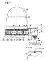
- a lathe in which a horrier constructive invention can be used comprises, as shown in Fig. 1, one in one Spindle housing 10 mounted workpiece spindle 12, which in the spindle housing 10 rotatably mounted about a spindle axis 14 and rotationally driven is.
- the workpiece spindle 12 is a designated as a whole by 16 workpiece fixable and rotatable about the spindle axis 14 for machining the same.
- the machining of the workpiece 16 is effected by a tool W, in FIG. 1
- a tool W for example, shown as a drill, which by a 20 as a whole designated tool carrier relative to the spindle axis 14 movable and is positionable.
- the tool holder 20 is formed, for example, as a revolver and includes a turret housing 22, on which a turret 24 about a turret axis 26 is rotatably mounted.
- the turret 24 is provided with a plurality of tool stations 28 each of the tool stations 28 has a support side 30, on which a tool holder body 32 of a designated as a whole with 34 Tool holder with an attachment side 36 can be placed while one of the Abutment surface 36 projecting shaft 38 of the tool holder 34 in a for this intended receptacle 40 of the tool station 28 can be used and in the receptacle 40 by engaging in a toothing of the shaft 38 provided with a counter toothing clamping element is fixable.
- the Fixation of the shaft 38 in the receptacle 40 takes place, for example, accordingly DIN 69880.
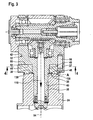
- the tool holder body 32 includes a Housing 42 to which the shaft 38 is formed and one on the Housing 42 of the support side 30 facing arranged support plate 44, which a subsequent to the shaft 38 cylindrical projection 46th with a cylindrical inner surface 48 encloses and with a support surface 50th the housing 42 carries, which on this support surface 50 with a support surface 52 is present.
- the housing 42 and the support plate 44 are relative to each other about an axis 54 of the shaft 38 rotatable, wherein the cylindrical projection 46 in the cylindrical inner surface 48 of the support plate 44 rotatable about the axis 54 is guided and also the support surface 52 relative to the support surface 50th can slide. Furthermore, the housing 42 relative to the support plate 44 by means cooperating alignment elements 56, 57 alignable about the axis 54, wherein a first alignment member 56 (Fig. 3) as a seated in the housing 42 pin is formed, which is in a bore 57 in the support plate 44 with play extends therein (Fig.
- the housing 42 and the support plate 44 are also different kind of alignment elements or fixing fixed, these elements either usable for alignment of the housing 42 to the support plate 44 Thumbscrews or screws can be the housing in its orientation set relative to the support plate 44 by positive engagement or adhesion.
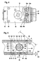
- the bearing sides 30 of the tool stations are 28 preferably as flattened peripheral surfaces of the disc-shaped Turret 24 is formed, extending between a front End face 62 and a rear end face 64 of the disc-shaped turret 24 extend in the direction of the turret axis 26 and in a circumferential direction or Azimutalcardi 66 to the turret axis 26 maximum to successive Edges 68 and 70 of the flattened bearing sides 30 provided disc-shaped turret 24 extend.
- the support side 30 of the Turret 24 in their on the front end side 62 and the rear end face 64 adjacent outer areas 72 and 74 with first positive locking elements 76 and 78, which extends with a longitudinal direction 80 of a Edge 68 to the other edge 70 in the azimuthal direction or circumferential direction 66 extend and thus lying near the edge 68 opposite Corners 82 and 84 lying opposite the edge 70 opposite Corner portions 86 and 88 of the support side 30 run.
- the plant side 36 which extends in the direction the turret axis 26 extends over the same distance as that between the End faces 62 and 64 lying support side 30, in on opposite Side of the shaft 38 lying outside areas 92 and 94 with second Form-locking elements 96 and 98 provided, which are with their longitudinal direction 100 of corner areas 102 and 104 to opposite corner areas 106 and 108 of the plant side 36 extend, wherein the corner regions 102 and 104 near an approximately parallel to the turret axis 26 lying Side edge 110 and the corner portions 106 and 108 near a shaft 38th opposite and also approximately parallel to the turret axis 36th extending side edge 112 of the support side 30 lie.
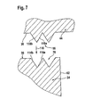
- the mutually facing fixing flanks 114a, b extend the first positive locking elements 76, 78 V-shaped.
- the second positive locking elements 96, 98 include by way of example represented by the example of the positive locking elements 96 outer edges 118a, 118b pointing in opposite directions and across the Insertion direction 116 with increasing extent of the same in the insertion direction 116 have a smaller distance from each other.
- the outer edges 118a, b are V-shaped.
- the fixing flanks 114a, 114b and the outer flanks 118a, 118b extend parallel to the longitudinal directions 80 and 100 of the first positive locking elements 76, 78 and the second positive locking elements 96, 98, so that the first positive locking elements 76, 78 relative to the second positive locking elements 96, 98 in the direction of the longitudinal directions 80, 100 relative to each other are movable and an exact positioning only in a transverse to the Provide longitudinal directions 80, 100 extending first positioning 120.
- each of the first positive locking elements 76, 78 more than one pair preferably has two pairs of mutually facing Fixierflanken 114a, b and each of the second interlocking elements 96, 98 more than one pair, preferably two pairs of outer edges facing in opposite directions 118a, b.
- the shaft 38 in the receptacle 40 by moving in Direction can be used parallel to the insertion direction 116, carried out with insertion of the shaft 38 in the receptacle 40 and thus with application of the plant side 36th the support plate 44 on the support side 30 an engaging the second Positive locking elements 96 and 98 with the first positive locking elements 76 and 78, which are arranged in the region of the contact side 36 and the support side 30 are.
- the plant side 36 does not necessarily extend to the Edges 68 and 70, but may terminate at a distance from them, as in FIG. 5 is indicated by the dashed lines, so that the support side 30th extends according to the plant side 36.
- Each of the first positive locking elements 76, 78 forms with the corresponding second positive locking element 96, 98 an alignment device 136, 138, wherein the two alignment devices 136, 138 by their arrangement opposite sides of the receptacle 40 and their extent to the Corner areas 82 and 86 or 84 and 88 as the maximum support length the length of diagonals 140, 140 of the support side 30, the diagonal 140 extends from the corner region 82 to the corner region 88 of the support side 30 and the diagonal 142 from the corner region 84 to the corner region 86 of the support side 30th extends and thus end portions 144 and 146 of the diagonal 140 in the corner areas 82 and 88 and end portions 148 and 150 of the diagonal 142 in the Corner areas 84 and 86 are.
- the diagonals 140, 142 of the support side 30 correspond to diagonals 160, 162 of the contact side 36 with lying in the corner regions 102 and 108 end portions 164, 166 and 168, 170 respectively.
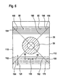
- the cooperating interlocking elements 76, 78 and 96, 98 allow in a second positioning direction 180, which is transverse to the first positioning direction 120 runs, no positive fixing but let in this Direction one degree of freedom, so that a slight movement of the Tool holder 34, in the second positioning direction 180 is possible, the when clamping the shaft 38 in the receptacle 40 by a toothing on 182 of the shaft 38 acting counter teeth 184 of a clamping element the receptacle 40 due to a force acting on the shaft 38 Transverse force 186 arises, which is parallel to the longitudinal direction 80, 100 of the interlocking elements 76, 78, 96, 98 acts and the shaft 38 subjected to force against one of the counter teeth 184 opposite contour 188 of the receptacle 40 applies, so that thereby the tool holder 34 in the second positioning direction 180 relative to the turret 24 accurately positioned becomes.
- the mobility of the positive locking elements 76, 78, 96, 98 in the second Positioning 180 adversely affected - as shown in Fig. 8 - the Alignment of a tool axis 190 of the tool W relative to the spindle axis 14 and thus to the Z-direction of the machine tool only insofar as by a movement in the second positioning direction 180 nor a parallel shift opposite the spindle axis 14 is possible.
Landscapes
- Engineering & Computer Science (AREA)
- Mechanical Engineering (AREA)
- Cutting Tools, Boring Holders, And Turrets (AREA)
- Jigs For Machine Tools (AREA)
- Machine Tool Units (AREA)
Abstract
Description
- Fig. 1
- eine Draufsicht auf Werkstückspindel und Werkzeugträger einer Werkzeugmaschine;
- Fig. 2
- eine perspektivische Darstellung eines erfindungsgemäß an einem Werkzeugträger fixierten Werkzeughalters;
- Fig. 3
- einen Schnitt längs Linie 3-3 in Fig. 2;
- Fig. 4
- einen Schnitt längs Linie 4-4 in Fig. 3;
- Fig. 5
- eine Draufsicht auf eine Auflageseite des Werkzeugträgers mit geschnitten dargestelltem Schaft;
- Fig. 6
- eine Draufsicht auf eine Anlageseite des Werkzeughalters mit geschnitten dargestelltem Schaft;
- Fig. 7
- eine vergrößerte Darstellung des Bereichs A in Fig. 3 bei von der Auflageseite abgehobener Anlageseite und
- Fig. 8
- eine Ansicht in Richtung des Pfeils B in Fig. 1.
Claims (45)
- Werkzeugmaschine umfassend einen Werkzeugträger (24) mit mindestens einer Werkzeugstation (28), welche eine Auflageseite (30) für eine Anlageseite (36) eines Werkzeughalters (34) und eine Aufnahme (40) für einen Schaft (38) des Werkzeughalters (34) aufweist, wobei die Anlageseite (36) dann gegen die Auflageseite (30) anliegt, wenn der Werkzeughalter (34) mit seinem Schaft (38) in der Aufnahme (40) eingespannt ist, und mindestens ein erstes Formschlußelement (76, 78), welches bei in der Aufnahme (40) eingespanntem Schaft (38) spielfrei in ein zweites Formschlußelement (96, 98) am Werkzeughalter (34) eingreift, um den Werkzeughalterkörper (32) relativ zum Werkzeugträger (24) präzise ausgerichtet zu fixieren,
dadurch gekennzeichnet, daß mindestens zwei auf einander gegenüberliegenden Seiten der Aufnahme (40) angeordnete erste Formschlußelemente (76, 78) vorgesehen sind und daß die ersten Formschlußelemente (76, 78) mindestens in einander gegenüberliegenden Außenbereichen (72, 74) der Auflageseite (30) angeordnet sind. - Werkzeugmaschine nach Anspruch 1, dadurch gekennzeichnet, daß die ersten Formschlußelemente (76, 78) in sich an Stirnseiten (62, 64) des Werkzeugträgers (24) anschließenden Außenbereichen (72, 74) der Auflageseite (30) angeordnet sind.
- Werkzeugmaschine nach Anspruch 1 oder 2, dadurch gekennzeichnet, daß die ersten Formschlußelemente (76, 78) mindestens in einander gegenüberliegenden Eckbereichen (82, 88; 84, 86) der Auflageseite angeordnet sind.
- Werkzeugmaschine nach einem der voranstehenden Ansprüche, dadurch gekennzeichnet, daß die ersten Formschlußelemente (76, 78) mindestens in Endbereichen (144, 146, 148, 150) einer Diagonalen (140, 142) der Auflageseite (30) angeordnet sind.
- Werkzeugmaschine nach einem der voranstehenden Ansprüche, dadurch gekennzeichnet, daß die ersten Formschlußelemente (76, 78) symmetrisch zu der Aufnahme (40) angeordnet sind.
- Werkzeugmaschine nach Anspruch 4 oder 5, dadurch gekennzeichnet, daß die ersten Formschlußelemente (76, 78) in Endbereichen (144, 146, 148, 150) beider Diagonalen (140, 142) der Auflageseite (30) angeordnet sind.
- Werkzeugmaschine nach einem der voranstehenden Ansprüche, dadurch gekennzeichnet, daß die ersten Formschlußelemente (76, 78) eine nur in einer ersten Positionierrichtung (120) die zweiten Formschlußelemente (96, 98) präzise positionierende Formschlußgeometrie (114) aufweisen.
- Werkzeugmaschine nach Anspruch 7, dadurch gekennzeichnet, daß die erste Positionierrichtung (120) quer zu einer auf den Schaft (38) beim Einspannen in die Aufnahme (40) wirkenden Querkraft (186) verläuft.
- Werkzeugmaschine nach Anspruch 7 oder 8, dadurch gekennzeichnet, daß die ersten Formschlußelemente (76, 78) eine in einer quer zur ersten (120) verlaufenden zweiten Positionierrichtung (180) die zweiten Formschlußelemente (96, 98) mit einem Freiheitsgrad verschieblich führende Formschlußgeometrie (114) aufweisen.
- Werkzeugmaschine nach Anspruch 9, dadurch gekennzeichnet, daß die zweite Positionierrichtung (180) ungefähr parallel zu einer auf den Schaft (38) beim Einspannen in die Aufnahme (40) wirkenden Querkraft (186) verläuft.
- Werkzeugmaschine nach einem der voranstehenden Ansprüche, dadurch gekennzeichnet, daß die ersten Formschlußelemente (76, 78) sich in einer Längsrichtung (80) erstrecken und in einer Ebene senkrecht zur Längsrichtung (80) eine konstante Querschnittsform (14) aufweisen.
- Werkzeugmaschine nach Anspruch 11, dadurch gekennzeichnet, daß die Querschnittsform (14) der ersten Formschlußelemente (76, 78) zumindest zum Teil durch schräg zueinander verlaufende Flanken (14) gebildet ist.
- Werkzeugmaschine nach Anspruch 11 oder 12, dadurch gekennzeichnet, daß die ersten Formschlußelemente (76, 78) sich mit ihrer Längsrichtung (80) ungefähr parallel zu einer auf den Schaft (38) beim Einspannen in der Aufnahme wirkenden Querkraft (186) erstrecken.
- Werkzeugmaschine nach einem der voranstehenden Ansprüche, dadurch gekennzeichnet, daß die ersten Formschlußelemente (76, 78) starr am Werkzeugträger (24) angeordnet sind.
- Werkzeugmaschine nach Anspruch 14, dadurch gekennzeichnet, daß die ersten Formschlußelemente (76, 78) an die Auflageseite (30) des Werkzeugträgers (24) angeformt sind.
- Werkzeugmaschine nach Anspruch 15, dadurch gekennzeichnet, daß die ersten Formschlußelemente (76, 78) als Vertiefungen in die Auflageseite (30) eingeformt sind.
- Werkzeugmaschine nach einem der voranstehenden Ansprüche, dadurch gekennzeichnet, daß die Formschlußelemente (76, 78, 96, 98) durch Einsetzen des Schafts (38) des Werkzeughalters (34) in die Aufnahme (40) in einer Einsetzrichtung (116) in Eingriff bringbar sind.
- Werkzeugmaschine nach einem der voranstehenden Ansprüche, dadurch gekennzeichnet, daß die einen der Formschlußelemente (96, 98) als V-förmige Verzahnung und die anderen der Formschlußelemente (76, 78) als die Verzahnung aufnehmende V-Nut ausgebildet sind.
- Werkzeugmaschine nach Anspruch 18, dadurch gekennzeichnet, daß die einen der Formschlußelemente (96, 98) als Mehrfachverzahnung und die anderen der Formschlußelemente (96, 98) als Mehrfachnut ausgebildet sind.
- Werkzeughalter für eine Werkzeugmaschine, umfassend einen das Werkzeug (W) tragenden Werkzeughalterkörper (32), welcher eine Anlageseite (36) aufweist und einen von dieser abstehenden Schaft (38) zum Einspannen des Werkzeughalters (34) in einer Werkzeugstation (28) eines Werkzeugträgers (34) trägt, und ein zweites Formschlußelement (96, 98), welches bei in der Aufnahme (40) eingespanntem Schaft (38) spielfrei in ein erstes Formschlußelement (76, 78) des Werkzeugträgers (24) eingreift, um den Werkzeughalterkörper (32) relativ zum Werkzeugträger (24) präzise ausgerichtet zu fixieren, dadurch gekennzeichnet, daß mindestens auf zwei einander gegenüberliegenden Seiten des Schaftes (38) angeordnete zweite Formschlußelemente (96, 98) vorgesehen sind und daß die zweiten Formschlußelemente (96, 98) mindestens in einander gegenüberliegenden Außenbereichen (92, 94) der Anlageseite (36) angeordnet sind.
- Werkzeughalter nach Anspruch 20, dadurch gekennzeichnet, daß die zweiten Formschlußelemente (96, 98) mindestens in einander gegenüberliegenden Eckbereichen (102, 108; 104, 106) der Anlageseite (36) angeordnet sind.
- Werkzeughalter nach Anspruch 20 oder 21, dadurch gekennzeichnet, daß die zweiten Formschlußelemente (96, 98) mindestens in einander gegenüberliegenden Endbereichen (164, 170; 166, 168) mindestens einer Diagonalen (160, 162) der Anlageseite (36) angeordnet sind.
- Werkzeughalter nach einem der Ansprüche 20 bis 22, dadurch gekennzeichnet, daß die zweiten Formschlußelemente (96, 98) symmetrisch zu dem Schaft (38) angeordnet sind.
- Werkzeughalter nach Anspruch 23, dadurch gekennzeichnet, daß die zweiten Formschlußelemente (96, 98) in Endbereichen (164, 170; 166, 168) beider Diagonalen (160, 162) der Anlageseite (36) angeordnet sind.
- Werkzeughalter nach einem der Ansprüche 20 bis 24, dadurch gekennzeichnet, daß die zweiten Formschlußelemente (96, 98) eine nur in einer ersten Positionierrichtung (120) die ersten Formschlußelemente (76, 78) präzise positionierende Formschlußgeometrie (118) aufweisen.
- Werkzeughalter nach Anspruch 25, dadurch gekennzeichnet, daß die erste Positionierrichtung (120) quer zu einer auf den Schaft (38) beim Einspannen in die Aufnahme (40) wirkenden Querkraft (186) verläuft.
- Werkzeughalter nach einem der Ansprüche 20 bis 26, dadurch gekennzeichnet, daß die zweiten Formschlußelemente (96, 98) eine in einer quer zur ersten (120) verlaufenden zweiten Positionierrichtung (180) die ersten Formschlußelemente (76, 78) mit einem Freiheitsgrad verschieblich führende Formschlußgeometrie (118) aufweisen.
- Werkzeughalter nach Anspruch 27, dadurch gekennzeichnet, daß die zweite Positionierrichtung (180) ungefähr parallel zu einer auf den Schaft (38) beim Einspannen in die Aufnahme (40) wirkenden Querkraft (186) verläuft.
- Werkzeughalter nach einem der Ansprüche 20 bis 28, dadurch gekennzeichnet, daß die zweiten Formschlußelemente (96, 98) sich in einer Längsrichtung (100) erstrecken und in einer Ebene senkrecht zur Längsrichtung (100) eine konstante Querschnittsform (118) aufweisen.
- Werkzeughalter nach Anspruch 29, dadurch gekennzeichnet, daß die Querschnittsform (118) der zweiten Formschlußelemente (96, 98) zumindest zum Teil durch schräg zueinander verlaufende Flanken (118) gebildet ist.
- Werkzeughalter nach einem der Ansprüche 20 bis 30, dadurch gekennzeichnet, daß die Formschlußelemente (96, 98) sich mit ihrer Längsrichtung (100) ungefähr parallel zu einer auf den Schaft (38) beim Einspannen in der Aufnahme (40) wirkenden Querkraft (186) erstrecken.
- Werkzeughalter nach einem der Ansprüche 20 bis 31, dadurch gekennzeichnet, daß die zweiten Formschlußelemente (96, 98) an einer bei in der Aufnahme (40) eingespanntem Schaft (38) in Richtung des Werkzeugträgers (24) kraftbeaufschlagten Stützplatte (44) des Werkzeughalterkörpers (32) angeordnet sind.
- Werkzeughalter nach Anspruch 32, dadurch gekennzeichnet, daß die Stützplatte (44) auf einer dem Werkzeugträger (24) zugewandten Seite eines den Schaft (38) tragenden Gehäuses (42) des Werkzeugträgers (34) angeordnet ist.
- Werkzeughalter nach Anspruch 32 oder 33, dadurch gekennzeichnet, daß die zweiten Formschlußelemente (96, 98) einstückig an die Stützplatte angeformt sind.
- Werkzeughalter nach einem der Ansprüche 20 bis 34, dadurch gekennzeichnet, daß die zweiten Formschlußelemente (96, 98) an dem Werkzeughalterkörper (32) justierbar angeordnet sind.
- Werkzeughalter nach Anspruch 35, dadurch gekennzeichnet, daß die Stützplatte (44) gegenüber dem Gehäuse (42) des Werkzeughalterkörpers (32) justierbar und fixierbar ist.
- Werkzeughalter nach einem der Ansprüche 20 bis 36, dadurch gekennzeichnet, daß die Formschlußelemente (76, 78, 96, 98) durch Einsetzen des Schafts (38) in die Aufnahme (40) in einer Einsetzrichtung (116) in Eingriff bringbar sind.
- Werkzeughalter nach einem der Ansprüche 20 bis 37, dadurch gekennzeichnet, daß die einen der Formschlußelemente (96, 98) als V-förmige Verzahnung und die andere der Formschlußelemente (76, 78) als die Verzahnung aufnehmende V-Nut ausgebildet sind.
- Werkzeughalter nach Anspruch 38, dadurch gekennzeichnet, daß die einen der Formschlußelemente (96, 98) als Mehrfachverzahnung und die anderen der Formschlußelemente (76, 78) als Mehrfachnut ausgebildet sind.
- Werkzeugfixiereinrichtung für Werkzeugmaschinen, umfassend einen Werkzeughalter (34) mit einem das Werkzeug (W) tragenden Werkzeughalterkörper (32), welcher eine Anlageseite (36) aufweist und einen von dieser abstehenden Schaft (38) zum Einspannen des Werkzeughalters (34) trägt, einen Werkzeugträger (24) mit mindestens einer Werkzeugstation (28), umfassend eine Auflageseite (30) und eine Aufnahme (40) für den Schaft (38), wobei die Anlageseite (36) dann gegen die Auflageseite (30) anliegt, wenn der Werkzeughalter (34) mit seinem Schaft (38) in der Aufnahme (40) eingespannt ist, und mindestens eine zwischen Werkzeughalterkörper (32) und Werkzeugträger (24) wirkende Ausrichtvorrichtung (136, 138) zur Positionierung des Werkzeughalterkörpers (32) relativ zum Werkzeugträger (24), die bei in der Aufnahme (40) eingespanntem Schaft (38) mittels am Werkzeugträger (24) und am Werkzeughalterkörper (32) angeordneten und spielfrei ineinandergreifenden Formschlußelementen (76, 78, 96, 98) den Werkzeugträger und den Werkzeughalterkörper relativ zueinander in einer einzigen Stellung ausgerichtet fixiert, dadurch gekennzeichnet, daß mindestens zwei aufeinander gegenüberliegenden Seiten des in die Aufnahme (40) eingespannten Schaftes (38) angeordnete Ausrichtvorrichtungen (136, 138) vorgesehen sind und daß die Ausrichtvorrichtungen (136, 138) mindestens in einander gegenüberliegenden Außenbereichen (72, 74, 92, 94) der Auflageseite (30) und/oder der Anlageseite (36) eine wirksame spielfreie Verbindung zwischen dem Werkzeugträger (24) und dem Werkzeughalterkörper (32) herstellen.
- Werkzeugfixiereinrichtung nach Anspruch 40, dadurch gekennzeichnet, daß die Ausrichtvorrichtungen (136, 138) eine Ausrichtung des Werkzeughalters (34) gegen eine Verdrehung um den in die Aufnahme (40) eingesetzten Schaft (38) bewirken.
- Werkzeugfixiereinrichtung nach Anspruch 40 oder 41, dadurch gekennzeichnet, daß die Ausrichtvorrichtungen (136, 138) eine exakte Ausrichtung des Werkzeughalters (34) gegenüber dem Werkzeugträger (24) nur in einer ersten Positionierrichtung (120) bewirken und einen Freiheitsgrad in einer quer zur ersten verlaufenden zweiten Positionierrichtung (180) zulassen.
- Werkzeugfixiereinrichtung nach Anspruch 42, dadurch gekennzeichnet, daß beim Einspannen des Schaftes (38) in die Aufnahme (40) entstehende, quer zum Schaft (38) wirkende Querkräfte (186) ungefähr parallel zur zweiten Positionierrichtung (180) verlaufen.
- Werkzeugfixiereinrichtung nach einem der Ansprüche 40 bis 43, dadurch gekennzeichnet, daß die Ausrichteinrichtungen (136, 138) mindestens in einander gegenüberliegenden Eckbereichen (82, 88; 84, 86; 102, 108; 104, 106) der Auflageseite (30) und/oder der Anlageseite (36) angeordnet sind.
- Werkzeugfixiereinrichtung nach einem der Ansprüche 40 bis 44, dadurch gekennzeichnet, daß die Ausrichteinrichtungen (136, 138) mindestens in einander gegenüberliegenden Endbereichen (144, 146; 148, 150; 164, 166; 168, 170) mindestens einer Diagonalen (140, 142; 160, 162) der Auflageseite (30) und/oder der Anlageseite (36) angeordnet sind.
Applications Claiming Priority (2)
| Application Number | Priority Date | Filing Date | Title |
|---|---|---|---|
| DE10343327A DE10343327A1 (de) | 2003-09-11 | 2003-09-11 | Werkzeugmaschine und hierzu vorgesehener Werkzeugträger |
| DE10343327 | 2003-09-11 |
Publications (3)
| Publication Number | Publication Date |
|---|---|
| EP1514623A2 true EP1514623A2 (de) | 2005-03-16 |
| EP1514623A3 EP1514623A3 (de) | 2008-05-28 |
| EP1514623B1 EP1514623B1 (de) | 2012-04-25 |
Family
ID=34129825
Family Applications (1)
| Application Number | Title | Priority Date | Filing Date |
|---|---|---|---|
| EP04021420A Expired - Lifetime EP1514623B1 (de) | 2003-09-11 | 2004-09-09 | Werkzeugmaschine und hierzu vorgesehener Werkzeugträger |
Country Status (3)
| Country | Link |
|---|---|
| EP (1) | EP1514623B1 (de) |
| AT (1) | ATE554870T1 (de) |
| DE (1) | DE10343327A1 (de) |
Cited By (2)
| Publication number | Priority date | Publication date | Assignee | Title |
|---|---|---|---|---|
| DE202010014484U1 (de) | 2010-10-19 | 2011-10-31 | Traub Drehmaschinen Gmbh & Co. Kg | Vorrichtung zur hochgenauen Montage auswechselbarer Werkzeuge oder Werkzeughalter an Drehmaschinen |
| EP3698906A1 (de) | 2019-02-25 | 2020-08-26 | Index-Werke GmbH & Co. KG Hahn & Tessky | Werkzeugträger und werkzeughalter |
Families Citing this family (2)
| Publication number | Priority date | Publication date | Assignee | Title |
|---|---|---|---|---|
| DE102009033805A1 (de) * | 2009-07-18 | 2011-01-27 | Sauter Feinmechanik Gmbh | Ausrichtvorrichtung |
| DE102019124524A1 (de) | 2019-09-12 | 2021-03-18 | Index-Werke Gmbh & Co. Kg Hahn & Tessky | Werkzeugmaschine |
Family Cites Families (5)
| Publication number | Priority date | Publication date | Assignee | Title |
|---|---|---|---|---|
| DE3130484A1 (de) * | 1981-07-23 | 1983-02-10 | Benz Gmbh Werkzeug- U. Maschinenbau Kg, 7612 Haslach | Schnellwechselwerkzeughalter, insbesondere fuer drehmaschinen |
| DE3435119C2 (de) * | 1984-09-25 | 1986-08-07 | Gildemeister-De Vlieg System-Werkzeuge Gmbh, 4800 Bielefeld | Werkzeug- oder Werkstückhalteranordnung für spanende Werkzeugmaschinen |
| DE19548151A1 (de) * | 1995-12-22 | 1997-07-17 | Index Werke Kg Hahn & Tessky | Werkzeugfixierung |
| DE19940330C2 (de) * | 1999-08-25 | 2001-06-13 | Esa Eppinger Gmbh | Werkzeugspanneinrichtung |
| SE520680C2 (sv) * | 2001-12-10 | 2003-08-12 | Sandvik Ab | Verktygshållare med adapter med divergerande sidoytor |
-
2003
- 2003-09-11 DE DE10343327A patent/DE10343327A1/de not_active Withdrawn
-
2004
- 2004-09-09 EP EP04021420A patent/EP1514623B1/de not_active Expired - Lifetime
- 2004-09-09 AT AT04021420T patent/ATE554870T1/de active
Cited By (2)
| Publication number | Priority date | Publication date | Assignee | Title |
|---|---|---|---|---|
| DE202010014484U1 (de) | 2010-10-19 | 2011-10-31 | Traub Drehmaschinen Gmbh & Co. Kg | Vorrichtung zur hochgenauen Montage auswechselbarer Werkzeuge oder Werkzeughalter an Drehmaschinen |
| EP3698906A1 (de) | 2019-02-25 | 2020-08-26 | Index-Werke GmbH & Co. KG Hahn & Tessky | Werkzeugträger und werkzeughalter |
Also Published As
| Publication number | Publication date |
|---|---|
| ATE554870T1 (de) | 2012-05-15 |
| DE10343327A1 (de) | 2005-04-07 |
| EP1514623A3 (de) | 2008-05-28 |
| EP1514623B1 (de) | 2012-04-25 |
Similar Documents
| Publication | Publication Date | Title |
|---|---|---|
| EP1961515B1 (de) | Kupplungseinrichtung und Kupplungselement für Werkzeughalter oder Werkstückspanneinrichtungen | |
| EP1027955B1 (de) | Werkzeugmaschine | |
| EP1038617B1 (de) | Werkzeughalter und Werkzeugmaschine | |
| EP0353436B1 (de) | Einstellvorrichtung, insbesondere für Werkzeuge | |
| EP2021149B1 (de) | Werkzeugmaschine | |
| DE10116994A1 (de) | Werkzeugmaschine | |
| EP0416610B1 (de) | Werkzeugträgeranordnung, insbesondere für Drehmaschinen, mit auswechselbaren Werkzeughaltern | |
| EP1854580A2 (de) | Werkzeugmaschine | |
| EP0962280B1 (de) | Ausrichteinrichtung | |
| EP1878534B1 (de) | Vorrichtung zum Ausrichten einer Werkzeugspindel mittels eines Scharniers | |
| DE602005002612T2 (de) | Werkzeugrevolver | |
| EP1815939B1 (de) | Halterung für eine Spanneinheit mit über Führungsnuten und Nutensteine verschiebbaren Stellplatten und Konsole ; Spannvorrichtung mit einer solchen Halterung | |
| DE10213778A1 (de) | Werkzeugmaschine | |
| DE3438598C1 (de) | Fräseinrichtung für einen Werkzeugträger einer Drehmaschine | |
| EP1514623B1 (de) | Werkzeugmaschine und hierzu vorgesehener Werkzeugträger | |
| EP0416611B1 (de) | Anordnung eines auswechselbaren Werkzeughalters an einem Revolverkopf einer Drehmaschine | |
| DE20321518U1 (de) | Werkzeugmaschine und hierzu vorgesehener Werkzeugträger | |
| EP1559490B1 (de) | Werkzeughalter | |
| DE19910953A1 (de) | Werkzeugmaschine | |
| DE10145672A1 (de) | Werkzeugmaschine | |
| DE19649016B4 (de) | Drehmaschine | |
| DE20009102U1 (de) | Ausrichteinrichtung | |
| DE19952361A1 (de) | Werkzeugmaschine | |
| EP3456471A1 (de) | Werkzeughalter und bearbeitungsgruppe mit einem derartigen werkzeughalter | |
| EP3208016A2 (de) | Werkzeughalter, werkzeugschlitten und langdrehmaschine |
Legal Events
| Date | Code | Title | Description |
|---|---|---|---|
| PUAI | Public reference made under article 153(3) epc to a published international application that has entered the european phase |
Free format text: ORIGINAL CODE: 0009012 |
|
| AK | Designated contracting states |
Kind code of ref document: A2 Designated state(s): AT BE BG CH CY CZ DE DK EE ES FI FR GB GR HU IE IT LI LU MC NL PL PT RO SE SI SK TR |
|
| AX | Request for extension of the european patent |
Extension state: AL HR LT LV MK |
|
| PUAL | Search report despatched |
Free format text: ORIGINAL CODE: 0009013 |
|
| AK | Designated contracting states |
Kind code of ref document: A3 Designated state(s): AT BE BG CH CY CZ DE DK EE ES FI FR GB GR HU IE IT LI LU MC NL PL PT RO SE SI SK TR |
|
| AX | Request for extension of the european patent |
Extension state: AL HR LT LV MK |
|
| 17P | Request for examination filed |
Effective date: 20081031 |
|
| AKX | Designation fees paid |
Designated state(s): AT BE BG CH CY CZ DE DK EE ES FI FR GB GR HU IE IT LI LU MC NL PL PT RO SE SI SK TR |
|
| 17Q | First examination report despatched |
Effective date: 20090417 |
|
| GRAP | Despatch of communication of intention to grant a patent |
Free format text: ORIGINAL CODE: EPIDOSNIGR1 |
|
| GRAS | Grant fee paid |
Free format text: ORIGINAL CODE: EPIDOSNIGR3 |
|
| GRAA | (expected) grant |
Free format text: ORIGINAL CODE: 0009210 |
|
| AK | Designated contracting states |
Kind code of ref document: B1 Designated state(s): AT BE BG CH CY CZ DE DK EE ES FI FR GB GR HU IE IT LI LU MC NL PL PT RO SE SI SK TR |
|
| REG | Reference to a national code |
Ref country code: GB Ref legal event code: FG4D Free format text: NOT ENGLISH |
|
| REG | Reference to a national code |
Ref country code: CH Ref legal event code: NV Representative=s name: KIRKER & CIE S.A. Ref country code: CH Ref legal event code: EP |
|
| REG | Reference to a national code |
Ref country code: AT Ref legal event code: REF Ref document number: 554870 Country of ref document: AT Kind code of ref document: T Effective date: 20120515 |
|
| REG | Reference to a national code |
Ref country code: IE Ref legal event code: FG4D Free format text: LANGUAGE OF EP DOCUMENT: GERMAN |
|
| REG | Reference to a national code |
Ref country code: DE Ref legal event code: R096 Ref document number: 502004013466 Country of ref document: DE Effective date: 20120621 |
|
| REG | Reference to a national code |
Ref country code: NL Ref legal event code: VDEP Effective date: 20120425 |
|
| PG25 | Lapsed in a contracting state [announced via postgrant information from national office to epo] |
Ref country code: CY Free format text: LAPSE BECAUSE OF FAILURE TO SUBMIT A TRANSLATION OF THE DESCRIPTION OR TO PAY THE FEE WITHIN THE PRESCRIBED TIME-LIMIT Effective date: 20120425 Ref country code: SE Free format text: LAPSE BECAUSE OF FAILURE TO SUBMIT A TRANSLATION OF THE DESCRIPTION OR TO PAY THE FEE WITHIN THE PRESCRIBED TIME-LIMIT Effective date: 20120425 Ref country code: FI Free format text: LAPSE BECAUSE OF FAILURE TO SUBMIT A TRANSLATION OF THE DESCRIPTION OR TO PAY THE FEE WITHIN THE PRESCRIBED TIME-LIMIT Effective date: 20120425 Ref country code: PL Free format text: LAPSE BECAUSE OF FAILURE TO SUBMIT A TRANSLATION OF THE DESCRIPTION OR TO PAY THE FEE WITHIN THE PRESCRIBED TIME-LIMIT Effective date: 20120425 |
|
| PG25 | Lapsed in a contracting state [announced via postgrant information from national office to epo] |
Ref country code: SI Free format text: LAPSE BECAUSE OF FAILURE TO SUBMIT A TRANSLATION OF THE DESCRIPTION OR TO PAY THE FEE WITHIN THE PRESCRIBED TIME-LIMIT Effective date: 20120425 Ref country code: GR Free format text: LAPSE BECAUSE OF FAILURE TO SUBMIT A TRANSLATION OF THE DESCRIPTION OR TO PAY THE FEE WITHIN THE PRESCRIBED TIME-LIMIT Effective date: 20120726 Ref country code: PT Free format text: LAPSE BECAUSE OF FAILURE TO SUBMIT A TRANSLATION OF THE DESCRIPTION OR TO PAY THE FEE WITHIN THE PRESCRIBED TIME-LIMIT Effective date: 20120827 |
|
| PG25 | Lapsed in a contracting state [announced via postgrant information from national office to epo] |
Ref country code: CZ Free format text: LAPSE BECAUSE OF FAILURE TO SUBMIT A TRANSLATION OF THE DESCRIPTION OR TO PAY THE FEE WITHIN THE PRESCRIBED TIME-LIMIT Effective date: 20120425 Ref country code: SK Free format text: LAPSE BECAUSE OF FAILURE TO SUBMIT A TRANSLATION OF THE DESCRIPTION OR TO PAY THE FEE WITHIN THE PRESCRIBED TIME-LIMIT Effective date: 20120425 Ref country code: EE Free format text: LAPSE BECAUSE OF FAILURE TO SUBMIT A TRANSLATION OF THE DESCRIPTION OR TO PAY THE FEE WITHIN THE PRESCRIBED TIME-LIMIT Effective date: 20120425 Ref country code: RO Free format text: LAPSE BECAUSE OF FAILURE TO SUBMIT A TRANSLATION OF THE DESCRIPTION OR TO PAY THE FEE WITHIN THE PRESCRIBED TIME-LIMIT Effective date: 20120425 Ref country code: DK Free format text: LAPSE BECAUSE OF FAILURE TO SUBMIT A TRANSLATION OF THE DESCRIPTION OR TO PAY THE FEE WITHIN THE PRESCRIBED TIME-LIMIT Effective date: 20120425 Ref country code: NL Free format text: LAPSE BECAUSE OF FAILURE TO SUBMIT A TRANSLATION OF THE DESCRIPTION OR TO PAY THE FEE WITHIN THE PRESCRIBED TIME-LIMIT Effective date: 20120425 |
|
| PLBE | No opposition filed within time limit |
Free format text: ORIGINAL CODE: 0009261 |
|
| STAA | Information on the status of an ep patent application or granted ep patent |
Free format text: STATUS: NO OPPOSITION FILED WITHIN TIME LIMIT |
|
| BERE | Be: lapsed |
Owner name: INDEX-WERKE G.M.B.H. & CO. KG HAHN & TESSKY Effective date: 20120930 |
|
| 26N | No opposition filed |
Effective date: 20130128 |
|
| PG25 | Lapsed in a contracting state [announced via postgrant information from national office to epo] |
Ref country code: ES Free format text: LAPSE BECAUSE OF FAILURE TO SUBMIT A TRANSLATION OF THE DESCRIPTION OR TO PAY THE FEE WITHIN THE PRESCRIBED TIME-LIMIT Effective date: 20120805 Ref country code: MC Free format text: LAPSE BECAUSE OF NON-PAYMENT OF DUE FEES Effective date: 20120930 |
|
| REG | Reference to a national code |
Ref country code: DE Ref legal event code: R097 Ref document number: 502004013466 Country of ref document: DE Effective date: 20130128 |
|
| GBPC | Gb: european patent ceased through non-payment of renewal fee |
Effective date: 20120909 |
|
| REG | Reference to a national code |
Ref country code: IE Ref legal event code: MM4A |
|
| PG25 | Lapsed in a contracting state [announced via postgrant information from national office to epo] |
Ref country code: BG Free format text: LAPSE BECAUSE OF FAILURE TO SUBMIT A TRANSLATION OF THE DESCRIPTION OR TO PAY THE FEE WITHIN THE PRESCRIBED TIME-LIMIT Effective date: 20120725 Ref country code: BE Free format text: LAPSE BECAUSE OF NON-PAYMENT OF DUE FEES Effective date: 20120930 Ref country code: GB Free format text: LAPSE BECAUSE OF NON-PAYMENT OF DUE FEES Effective date: 20120909 Ref country code: IE Free format text: LAPSE BECAUSE OF NON-PAYMENT OF DUE FEES Effective date: 20120909 |
|
| REG | Reference to a national code |
Ref country code: AT Ref legal event code: MM01 Ref document number: 554870 Country of ref document: AT Kind code of ref document: T Effective date: 20120909 |
|
| PG25 | Lapsed in a contracting state [announced via postgrant information from national office to epo] |
Ref country code: AT Free format text: LAPSE BECAUSE OF NON-PAYMENT OF DUE FEES Effective date: 20120909 |
|
| PG25 | Lapsed in a contracting state [announced via postgrant information from national office to epo] |
Ref country code: TR Free format text: LAPSE BECAUSE OF FAILURE TO SUBMIT A TRANSLATION OF THE DESCRIPTION OR TO PAY THE FEE WITHIN THE PRESCRIBED TIME-LIMIT Effective date: 20120425 |
|
| PG25 | Lapsed in a contracting state [announced via postgrant information from national office to epo] |
Ref country code: LU Free format text: LAPSE BECAUSE OF NON-PAYMENT OF DUE FEES Effective date: 20120909 |
|
| PG25 | Lapsed in a contracting state [announced via postgrant information from national office to epo] |
Ref country code: HU Free format text: LAPSE BECAUSE OF FAILURE TO SUBMIT A TRANSLATION OF THE DESCRIPTION OR TO PAY THE FEE WITHIN THE PRESCRIBED TIME-LIMIT Effective date: 20040909 |
|
| REG | Reference to a national code |
Ref country code: DE Ref legal event code: R082 Ref document number: 502004013466 Country of ref document: DE Representative=s name: HOEGER, STELLRECHT & PARTNER PATENTANWAELTE MB, DE |
|
| REG | Reference to a national code |
Ref country code: FR Ref legal event code: PLFP Year of fee payment: 13 |
|
| REG | Reference to a national code |
Ref country code: FR Ref legal event code: PLFP Year of fee payment: 14 |
|
| REG | Reference to a national code |
Ref country code: FR Ref legal event code: PLFP Year of fee payment: 15 |
|
| REG | Reference to a national code |
Ref country code: DE Ref legal event code: R082 Ref document number: 502004013466 Country of ref document: DE Representative=s name: HOEGER, STELLRECHT & PARTNER PATENTANWAELTE MB, DE |
|
| P01 | Opt-out of the competence of the unified patent court (upc) registered |
Effective date: 20230517 |
|
| PGFP | Annual fee paid to national office [announced via postgrant information from national office to epo] |
Ref country code: FR Payment date: 20230921 Year of fee payment: 20 Ref country code: DE Payment date: 20230926 Year of fee payment: 20 |
|
| PGFP | Annual fee paid to national office [announced via postgrant information from national office to epo] |
Ref country code: IT Payment date: 20230926 Year of fee payment: 20 Ref country code: CH Payment date: 20231004 Year of fee payment: 20 |
|
| REG | Reference to a national code |
Ref country code: DE Ref legal event code: R071 Ref document number: 502004013466 Country of ref document: DE |
|
| REG | Reference to a national code |
Ref country code: CH Ref legal event code: PL |