EP1514683B1 - Procédé pour faire fonctionner une machine à imprimer - Google Patents
Procédé pour faire fonctionner une machine à imprimer Download PDFInfo
- Publication number
- EP1514683B1 EP1514683B1 EP04021092.4A EP04021092A EP1514683B1 EP 1514683 B1 EP1514683 B1 EP 1514683B1 EP 04021092 A EP04021092 A EP 04021092A EP 1514683 B1 EP1514683 B1 EP 1514683B1
- Authority
- EP
- European Patent Office
- Prior art keywords
- foil
- printing
- cylinder
- circumferential surface
- coarse structure
- Prior art date
- Legal status (The legal status is an assumption and is not a legal conclusion. Google has not performed a legal analysis and makes no representation as to the accuracy of the status listed.)
- Expired - Lifetime
Links
- 238000007639 printing Methods 0.000 title claims description 59
- 238000000034 method Methods 0.000 title claims description 17
- 239000011888 foil Substances 0.000 claims description 14
- 239000005871 repellent Substances 0.000 claims description 13
- 239000000463 material Substances 0.000 claims description 8
- 239000000853 adhesive Substances 0.000 claims description 5
- 230000002940 repellent Effects 0.000 claims description 5
- 229920001169 thermoplastic Polymers 0.000 claims description 3
- 230000007246 mechanism Effects 0.000 claims 2
- 239000002184 metal Substances 0.000 claims 2
- 239000010410 layer Substances 0.000 claims 1
- 239000002346 layers by function Substances 0.000 claims 1
- 239000002318 adhesion promoter Substances 0.000 description 8
- 239000007767 bonding agent Substances 0.000 description 5
- VYZAMTAEIAYCRO-UHFFFAOYSA-N Chromium Chemical compound [Cr] VYZAMTAEIAYCRO-UHFFFAOYSA-N 0.000 description 2
- 239000011248 coating agent Substances 0.000 description 2
- 238000000576 coating method Methods 0.000 description 2
- 238000010438 heat treatment Methods 0.000 description 2
- 238000002844 melting Methods 0.000 description 2
- 230000008018 melting Effects 0.000 description 2
- 239000004416 thermosoftening plastic Substances 0.000 description 2
- 238000009825 accumulation Methods 0.000 description 1
- 230000001070 adhesive effect Effects 0.000 description 1
- 238000007743 anodising Methods 0.000 description 1
- 230000015572 biosynthetic process Effects 0.000 description 1
- 230000001680 brushing effect Effects 0.000 description 1
- 229910052804 chromium Inorganic materials 0.000 description 1
- 239000011651 chromium Substances 0.000 description 1
- 150000001875 compounds Chemical class 0.000 description 1
- 230000006735 deficit Effects 0.000 description 1
- 230000001419 dependent effect Effects 0.000 description 1
- 229920006332 epoxy adhesive Polymers 0.000 description 1
- 238000004519 manufacturing process Methods 0.000 description 1
- 238000011089 mechanical engineering Methods 0.000 description 1
- 238000007645 offset printing Methods 0.000 description 1
- 229920001200 poly(ethylene-vinyl acetate) Polymers 0.000 description 1
- 238000003825 pressing Methods 0.000 description 1
- 230000000750 progressive effect Effects 0.000 description 1
- 238000005488 sandblasting Methods 0.000 description 1
- 239000004447 silicone coating Substances 0.000 description 1
- 238000005507 spraying Methods 0.000 description 1
- 239000000758 substrate Substances 0.000 description 1
- 239000012815 thermoplastic material Substances 0.000 description 1
- 239000001993 wax Substances 0.000 description 1
Images
Classifications
-
- B—PERFORMING OPERATIONS; TRANSPORTING
- B41—PRINTING; LINING MACHINES; TYPEWRITERS; STAMPS
- B41F—PRINTING MACHINES OR PRESSES
- B41F30/00—Devices for attaching coverings or make-ready devices; Guiding devices for coverings
- B41F30/02—Devices for attaching coverings or make-ready devices; Guiding devices for coverings attaching to impression cylinders
-
- B—PERFORMING OPERATIONS; TRANSPORTING
- B41—PRINTING; LINING MACHINES; TYPEWRITERS; STAMPS
- B41F—PRINTING MACHINES OR PRESSES
- B41F22/00—Means preventing smudging of machine parts or printed articles
-
- B—PERFORMING OPERATIONS; TRANSPORTING
- B41—PRINTING; LINING MACHINES; TYPEWRITERS; STAMPS
- B41N—PRINTING PLATES OR FOILS; MATERIALS FOR SURFACES USED IN PRINTING MACHINES FOR PRINTING, INKING, DAMPING, OR THE LIKE; PREPARING SUCH SURFACES FOR USE AND CONSERVING THEM
- B41N7/00—Shells for rollers of printing machines
-
- B—PERFORMING OPERATIONS; TRANSPORTING
- B41—PRINTING; LINING MACHINES; TYPEWRITERS; STAMPS
- B41N—PRINTING PLATES OR FOILS; MATERIALS FOR SURFACES USED IN PRINTING MACHINES FOR PRINTING, INKING, DAMPING, OR THE LIKE; PREPARING SUCH SURFACES FOR USE AND CONSERVING THEM
- B41N2207/00—Location or type of the layers in shells for rollers of printing machines
- B41N2207/02—Top layers
Definitions
- the present invention relates to a method of operating a printing press comprising a plurality of printing units with printing cylinders and a sheet turning device arranged between the printing units.
- the lateral surfaces of the sheet-guiding cylinders may come into contact with ink which has not completely dried.
- ink which has not completely dried.
- printing cylinders which are arranged in perfecting machines after the turning device, such contact in the production of double-sided sheet is technologically required.
- the outer surfaces of such pressure cylinder ink repellent In order to avoid the accumulation of printing ink on the lateral surfaces of the printing cylinder, designed the outer surfaces of such pressure cylinder ink repellent. This is achieved by the use of ink-repellent materials and by the creation of special structures which repel color and facilitate the removal of the printed sheets from the impression cylinder.
- the DE 42 07 119 A1 discloses a sheet-guiding printing cylinder shell profile for a printing cylinder in sheet-fed presses, which consists of statistically evenly distributed, forming the counter-pressure surface, arranged plane-parallel to the impression cylinder axis lines having a certain screen fineness. From the DE 199 14 136 A1 It is also known to produce on the surface of a sheet-guiding cylinder by coating with plasma an outward structure and to provide them with an organic, ink-repellent coating.
- the printing cylinder is formed by arranging additional fastening devices in such a way that an ink-repellent film acting as a counterpressure surface can be detachably fastened to the lateral surface of the printing cylinder.
- a printing cylinder of this type has a smooth surface. When dimensioning the circumference of the printing cylinder, the thickness of the film is taken into account.
- Serving as elevators for printing cylinder foils are usually constructed of the same materials as the outer surfaces acting as counter-pressure surfaces of the impression cylinder of the former type and have the same structure on Raupatented.
- a film of this kind is for example from the DE 39 31 479 A1 known. This consists of a chemically resistant, wear-resistant and incompressible carrier layer, on which a silicone coating is applied.
- From the DE 40 36 252 A1 is a sheet-guiding film known as an elevator for a printing cylinder of rotary offset printing machines for perfecting, one surface of which is smooth and the other surface is provided with evenly distributed spherical caps and a micro-roughness compensating chromium layer.
- Object of the present invention is, while avoiding the aforementioned disadvantages, a method for operating a perfecting press with a sheet turning device downstream pressure cylinder whose outer surface comprises a color-repellent acting RauWORK to create that allows for long periods of operation a consistent print quality without replacing the printing cylinder ,
- the decisive advantage of the method according to the invention is that a printing press with a color-repellent cylinder in the first years of operation in a known Operated manner using the ink-repellent properties of the outer surface of the printing cylinder and can be equipped with the achievement of the wear limit in a simple manner by arranging a film for further years of operation.
- This proves to be advantageous in particular in connection with the operation of such perfecting machines whose printing cylinder does not include means for attaching a color-guiding elevator, because a complex and associated with downtime replacement of the printing cylinder deleted.
- a further advantage consists in that, for carrying out the method according to the invention for operating a printing press, the materials used are merely a film which is designed to repel ink in a manner known per se, and adhesion promoters. In this case, the bonding agent takes the place of the fastening device in comparison to the known solutions.
- a preferred development of the invention provides to apply the film with the interposition of the adhesion promoter on the printing cylinder and while the printing cylinder rotates circumferentially with applied film to hire the provided for this purpose with a hard-lift blanket cylinder, so that this evenly presses the film until the primer has cured. This further improves the accuracy of applying the film, particularly to those films which are relatively rigid.
- a thermoplastic material is preferably used.
- compounds from the group of ethylene-vinyl acetate copolymers which have a melting range between about 130 ° and 180 ° C., which can be adjusted by adding modified waxes, have proven to be suitable.
- the bonding agent can also be used for the repair of printing cylinders, which is associated with an intermediate dryer and thus are exposed to increased heat load. To remove the film, such a bonding agent only needs to be heated.
- thermoplastic adhesion promoters having lower melting temperatures.
- thermoplastic adhesion promoters it is not necessary to completely remove them when replacing a worn film with a new one, since adhesive residues, after being fused, are for attachment a new film can be used and have the same properties as newly applied adhesion promoter.
- epoxy adhesives which cure chemically and require no heating can also be used as adhesion promoters.
- a heating of the printing cylinder can be used here specifically to accelerate the curing process.
- the application of the primer is done in a simple manner by brushing or spraying.
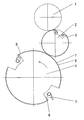
- the accompanying drawing shows a schematic representation of a printing unit with double-sized impression cylinder. 4
- the printing cylinder 4 together with its associated blanket cylinder 2 and the plate cylinder 1, a printing unit.
- the printing unit is part of an otherwise not shown printing machine, which includes a plurality of printing units and a sheet turning device, which is arranged downstream of it in the sheet running direction.
- the printing cylinder 4 carries two gripper systems, which are formed from grippers 5 and gripper mounts 6 and fix the printing material on the leading edge, while they are transported by the printing gap between the printing cylinder 4 and blanket cylinder 2.
- the lateral surface 9 of the printing cylinder 4 has a rough structure. In the illustrated state, this structure is already worn due to the continued contact with the printing material to the extent that it does not substantiate sufficient color-repellent properties.
- a film 7 is fixed on the lateral surface, which is smooth on its side facing the lateral surface 9 and whose side facing away from the lateral surface 9 has a color-rejecting structure.
- the lateral surface 9 is cleaned and then an adhesion promoter 8 is sprayed onto the lateral surface 9 and / or the lower side of the film 7.
- the pressing of the film 7 is carried out by the blanket cylinder 2, which is provided for this purpose with a hard elevator 3 and to which is turned on with applied film 7 printing cylinder 4.
- the adjustment takes place up to a pressure of between 0.05 and 0.2 mm.
- the printing pressure is increased in small steps until the specified values are reached, with the printing cylinder 4 making several revolutions after every change in the pressure.
- the bonding agent 8 is evenly distributed, which hardens gradually at a constant volume and compensates for unevenness of the printing cylinder 4.
- the blanket cylinder 2 acts with the applied hard elevator 3 as normal.
- the thickness of the applied film 7 is less than or equal to 0.3 mm, so that the printing press can always print substrates with thicknesses in the range up to 1 mm.
Landscapes
- Printing Plates And Materials Therefor (AREA)
- Printing Methods (AREA)
Claims (9)
- Procédé de gestion d'une machine d'impression ayant plusieurs groupes d'impression avec des cylindres d'impression et une installation de retournement de feuilles entre les groupes d'impression,- la surface enveloppe (9) d'au moins un cylindre d'impression (4) en aval de l'installation de retournement de feuilles et dans le sens de défilement des feuilles, a une structure rugueuse ayant un effet de répulsion d'encre,procédé selon lequel
on imprime des feuilles avec la machine d'impression jusqu'à ce que la structure rugueuse de la surface enveloppe (9) soit usée pour que l'effet de répulsion d'encre passe en-dessous d'un seuil prédéfini, et
ensuite sur la surface enveloppe (9) on installe un film (7) amovible dont le côté opposé à la surface enveloppe (9) a une structure rugueuse à effet de répulsion d'encre. - Procédé selon la revendication 1,
caractérisé en ce que
l'on remplace le film (7) rapporté, après traitement d'autres feuilles, par un film (7) analogue lorsque la structure rugueuse du film (7) rapporté est usée pour que son effet de répulsion d'encre passe en-dessous d'un seuil prédéfini. - Procédé selon la revendication 1 ou 2,
caractérisé en ce que
la surface enveloppe (9) du cylindre d'impression (4) et le film (7) ont la même structure rugueuse avant leur usure par le contact avec les feuilles. - Procédé selon l'une des revendications précédentes,
caractérisé en ce que
le film (7) est fixé par collage à l'aide d'un adhésif (8). - Procédé selon la revendication 4,
caractérisé en ce que le film (7) est appliqué sur le cylindre d'impression (4) avec interposition d'un adhésif (8) et, pendant que le cylindre d'impression (4) tourne avec le film (7) mis en place, pour être pressé par le cylindre branché, appliqué contre et muni à cet effet d'un revêtement dur (3) jusqu'à ce que l'adhésif (8) soit durci. - Procédé selon la revendication 4 ou 5,
caractérisé en ce que
l'adhésif (8) est une matière thermoplastique, que l'on chauffe pour fixer et pour enlever le film (7). - Procédé selon l'une des revendications précédentes,
caractérisé en ce que
l'on utilise un film métallique. - Procédé selon la revendication 7,
caractérisé en ce que
le film métallique a une épaisseur inférieure à 0,3 mm. - Procédé selon la revendication 7,
caractérisé en ce que
le film (7) a une couche de support élastique et une couche fonctionnelle à structure rugueuse.
Applications Claiming Priority (2)
| Application Number | Priority Date | Filing Date | Title |
|---|---|---|---|
| DE10341373 | 2003-09-09 | ||
| DE10341373 | 2003-09-09 |
Publications (2)
| Publication Number | Publication Date |
|---|---|
| EP1514683A1 EP1514683A1 (fr) | 2005-03-16 |
| EP1514683B1 true EP1514683B1 (fr) | 2013-06-05 |
Family
ID=34129694
Family Applications (1)
| Application Number | Title | Priority Date | Filing Date |
|---|---|---|---|
| EP04021092.4A Expired - Lifetime EP1514683B1 (fr) | 2003-09-09 | 2004-09-04 | Procédé pour faire fonctionner une machine à imprimer |
Country Status (3)
| Country | Link |
|---|---|
| US (1) | US7461595B2 (fr) |
| EP (1) | EP1514683B1 (fr) |
| DE (1) | DE102004043839A1 (fr) |
Families Citing this family (4)
| Publication number | Priority date | Publication date | Assignee | Title |
|---|---|---|---|---|
| DE102009016685B4 (de) | 2008-05-08 | 2020-06-04 | Heidelberger Druckmaschinen Ag | Flächenförmiger, Bedruckstoff führender Aufzug für einen Transportzylinder |
| DE102008060557B4 (de) | 2008-12-04 | 2018-11-22 | Heidelberger Druckmaschinen Ag | Verfahren zum Aufbringen eines Aufzugsblechs auf einen Druckzylinder einer Offsetdruckmaschine |
| DE102009009460A1 (de) | 2009-02-18 | 2010-08-19 | Manroland Ag | Bogenführungszylinder mit Aufzug in einer Verarbeitungsmaschine |
| DE102010010142B4 (de) | 2009-03-26 | 2022-03-17 | Heidelberger Druckmaschinen Ag | Bogenführungselement und Verfahren zur Herstellung eines Bogenführungselementes |
Citations (1)
| Publication number | Priority date | Publication date | Assignee | Title |
|---|---|---|---|---|
| DE3931479A1 (de) * | 1989-09-21 | 1991-04-04 | Heidelberger Druckmasch Ag | Bogenfuehrende folie als aufzug fuer gegendruckzylinder und bogenueberfuehrungszylinder in bogenoffsetdruckmaschinen fuer schoen- und widerdruck |
Family Cites Families (10)
| Publication number | Priority date | Publication date | Assignee | Title |
|---|---|---|---|---|
| US3161130A (en) | 1963-05-27 | 1964-12-15 | Miller Printing Machinery Co | Printing apparatus |
| DE2916505A1 (de) * | 1979-04-24 | 1980-10-30 | Heidelberger Druckmasch Ag | Bogenfuehrende folie als aufzug fuer gegendruckzylinder |
| US5042384A (en) * | 1990-04-30 | 1991-08-27 | Howard W. DeMoore | Anti-marking method and apparatus for use with perfector cylinders of rotary sheet-fed printing presses |
| DE4036252C1 (fr) | 1990-11-14 | 1992-01-02 | Heidelberger Druckmaschinen Ag, 6900 Heidelberg, De | |
| US5890430A (en) * | 1990-11-14 | 1999-04-06 | Heidelberger Druckmaschinen Ag | Impression cylinder having a multiple diameter and a sheet guiding foil |
| DE4207119C2 (de) | 1992-03-06 | 1999-09-02 | Roland Man Druckmasch | Bogenführendes Druckzylindermantelprofil |
| DE4323750C2 (de) * | 1993-07-15 | 1997-03-27 | Roland Man Druckmasch | Offset-Druckform und Verfahren zur Herstellung einer solchen Offset-Druckform |
| DE19914136B4 (de) | 1999-03-27 | 2009-02-26 | Koenig & Bauer Aktiengesellschaft | Oberfläche für Maschinenteile in Druckmaschinen |
| DE20107182U1 (de) * | 2001-04-26 | 2001-06-28 | Man Roland Druckmaschinen Ag, 63069 Offenbach | Bogenführungszylinder in einer Mehrfarben-Druckmaschine |
| US7082873B2 (en) * | 2002-02-25 | 2006-08-01 | Printing Research, Inc. | Inexpensive, wash-free integrated cover for printing press transfer cylinders |
-
2004
- 2004-09-04 EP EP04021092.4A patent/EP1514683B1/fr not_active Expired - Lifetime
- 2004-09-08 DE DE102004043839A patent/DE102004043839A1/de not_active Ceased
-
2005
- 2005-03-28 US US11/091,185 patent/US7461595B2/en not_active Expired - Fee Related
Patent Citations (1)
| Publication number | Priority date | Publication date | Assignee | Title |
|---|---|---|---|---|
| DE3931479A1 (de) * | 1989-09-21 | 1991-04-04 | Heidelberger Druckmasch Ag | Bogenfuehrende folie als aufzug fuer gegendruckzylinder und bogenueberfuehrungszylinder in bogenoffsetdruckmaschinen fuer schoen- und widerdruck |
Also Published As
| Publication number | Publication date |
|---|---|
| US7461595B2 (en) | 2008-12-09 |
| DE102004043839A1 (de) | 2005-04-07 |
| EP1514683A1 (fr) | 2005-03-16 |
| US20060213385A1 (en) | 2006-09-28 |
Similar Documents
| Publication | Publication Date | Title |
|---|---|---|
| EP2502753B1 (fr) | Blanchet polymère | |
| DE102009007002B4 (de) | Betrieb eines Kaltfolienaggregates mit einem Druckwerk | |
| EP1202863B1 (fr) | Dispositif de guidage courbe pour machine a imprimer | |
| EP2216174B1 (fr) | Procédé et dispositif de revêtement et d'imprégnation d'une matière imprimée dans une machine à imprimer | |
| EP1514683A1 (fr) | Procédé pour faire fonctionner une machine à imprimer | |
| EP0564856B1 (fr) | Procédé et dispositif pour le vernissage et l'impression à retiration de feuilles dans une unité de vernissage et d'impression à retiration | |
| EP1878987A2 (fr) | Dispositif de séchage destiné au traitement d'une surface de matière d'impression dans une machine de traitement | |
| DE102012218840A1 (de) | Folientransferverfahren | |
| DE10121827B4 (de) | Druckwerk mit reversibler Bebilderung und digitaler Umrüstung | |
| EP1514697B1 (fr) | Procédé de restauration de la surface d'un cylindre d'impression dans les machines d'impression | |
| EP1341669B1 (fr) | Dispositif de vernissage pour rotative a imprimer | |
| EP0931648B1 (fr) | Dispositif de couchage pour une machine à imprimer et plaque d'impression typographique | |
| DE10117409A1 (de) | Drucktuch zur Verwendung auf Druckzylindern für insbesondere Offset-Druckmaschinen | |
| DE102010064065A1 (de) | Verfahren zum Erzeugen einer Prägeform in einer Bogenrotationsdruckmaschine | |
| DE102009000573A1 (de) | Verfahren und Vorrichtung zur Veredelung eines Bedruckstoffes in einer Verarbeitungsmaschine | |
| DE102009009460A1 (de) | Bogenführungszylinder mit Aufzug in einer Verarbeitungsmaschine | |
| DE102013222175B4 (de) | Druckwerk einer Offsetrotationsdruckmaschine | |
| EP2222470A1 (fr) | Dispositif d'enduction équipé d'un cylindre porte-cliché et d'au moins un rouleau enducteur dans une machine de traitement | |
| EP1284859B1 (fr) | Habillage d'un cylindre porte-cliches de rotative | |
| DE102018217261A1 (de) | Druckverfahren und Bogendruckmaschine | |
| EP1390202B1 (fr) | Procede de production d'une plaque d'impression pouvant etre directement gravee au laser, et plaque d'impression produite selon ledit procede | |
| EP1147915A1 (fr) | Blanchet d'impression pour l'utilisation sur un cylindre d'impression en particulier pour machines d'impression offset | |
| EP1184172B1 (fr) | Cylindre porte-blanchet dans une machine offset rotative | |
| DE20102450U1 (de) | Lackiervorrichtung für eine Rotationsdruckmaschine | |
| DE20202014U1 (de) | Schichtkörper zum Verhüten des Verschmierens von Maschinenteilen oder Bedruckstoffen in einer Verarbeitungsmaschine |
Legal Events
| Date | Code | Title | Description |
|---|---|---|---|
| PUAI | Public reference made under article 153(3) epc to a published international application that has entered the european phase |
Free format text: ORIGINAL CODE: 0009012 |
|
| 17P | Request for examination filed |
Effective date: 20041202 |
|
| AK | Designated contracting states |
Kind code of ref document: A1 Designated state(s): AT BE BG CH CY CZ DE DK EE ES FI FR GB GR HU IE IT LI LU MC NL PL PT RO SE SI SK TR |
|
| AX | Request for extension of the european patent |
Extension state: AL HR LT LV MK |
|
| AKX | Designation fees paid |
Designated state(s): DE FR GB IT |
|
| 17Q | First examination report despatched |
Effective date: 20111229 |
|
| REG | Reference to a national code |
Ref country code: DE Ref legal event code: R079 Ref document number: 502004014212 Country of ref document: DE Free format text: PREVIOUS MAIN CLASS: B41F0022000000 Ipc: B41N0007000000 |
|
| GRAP | Despatch of communication of intention to grant a patent |
Free format text: ORIGINAL CODE: EPIDOSNIGR1 |
|
| RIC1 | Information provided on ipc code assigned before grant |
Ipc: B41F 30/02 20060101ALI20130123BHEP Ipc: B41N 7/00 20060101AFI20130123BHEP |
|
| GRAS | Grant fee paid |
Free format text: ORIGINAL CODE: EPIDOSNIGR3 |
|
| GRAA | (expected) grant |
Free format text: ORIGINAL CODE: 0009210 |
|
| AK | Designated contracting states |
Kind code of ref document: B1 Designated state(s): DE FR GB IT |
|
| REG | Reference to a national code |
Ref country code: GB Ref legal event code: FG4D Free format text: NOT ENGLISH |
|
| REG | Reference to a national code |
Ref country code: DE Ref legal event code: R096 Ref document number: 502004014212 Country of ref document: DE Effective date: 20130801 |
|
| PLBE | No opposition filed within time limit |
Free format text: ORIGINAL CODE: 0009261 |
|
| STAA | Information on the status of an ep patent application or granted ep patent |
Free format text: STATUS: NO OPPOSITION FILED WITHIN TIME LIMIT |
|
| 26N | No opposition filed |
Effective date: 20140306 |
|
| REG | Reference to a national code |
Ref country code: DE Ref legal event code: R097 Ref document number: 502004014212 Country of ref document: DE Effective date: 20140306 |
|
| PGFP | Annual fee paid to national office [announced via postgrant information from national office to epo] |
Ref country code: DE Payment date: 20140916 Year of fee payment: 11 |
|
| REG | Reference to a national code |
Ref country code: FR Ref legal event code: PLFP Year of fee payment: 12 |
|
| PGFP | Annual fee paid to national office [announced via postgrant information from national office to epo] |
Ref country code: GB Payment date: 20150924 Year of fee payment: 12 |
|
| PGFP | Annual fee paid to national office [announced via postgrant information from national office to epo] |
Ref country code: FR Payment date: 20150924 Year of fee payment: 12 |
|
| PGFP | Annual fee paid to national office [announced via postgrant information from national office to epo] |
Ref country code: IT Payment date: 20150930 Year of fee payment: 12 |
|
| REG | Reference to a national code |
Ref country code: DE Ref legal event code: R119 Ref document number: 502004014212 Country of ref document: DE |
|
| PG25 | Lapsed in a contracting state [announced via postgrant information from national office to epo] |
Ref country code: DE Free format text: LAPSE BECAUSE OF NON-PAYMENT OF DUE FEES Effective date: 20160401 |
|
| GBPC | Gb: european patent ceased through non-payment of renewal fee |
Effective date: 20160904 |
|
| REG | Reference to a national code |
Ref country code: FR Ref legal event code: ST Effective date: 20170531 |
|
| PG25 | Lapsed in a contracting state [announced via postgrant information from national office to epo] |
Ref country code: GB Free format text: LAPSE BECAUSE OF NON-PAYMENT OF DUE FEES Effective date: 20160904 Ref country code: FR Free format text: LAPSE BECAUSE OF NON-PAYMENT OF DUE FEES Effective date: 20160930 |
|
| PG25 | Lapsed in a contracting state [announced via postgrant information from national office to epo] |
Ref country code: IT Free format text: LAPSE BECAUSE OF NON-PAYMENT OF DUE FEES Effective date: 20160904 |