EP1514703A1 - Verfahren zur Erleichterung einer Notlaufvorrichtung für Kraftfahrzeugrad und Vorrichtung dadurch hergestellt - Google Patents
Verfahren zur Erleichterung einer Notlaufvorrichtung für Kraftfahrzeugrad und Vorrichtung dadurch hergestellt Download PDFInfo
- Publication number
- EP1514703A1 EP1514703A1 EP04291856A EP04291856A EP1514703A1 EP 1514703 A1 EP1514703 A1 EP 1514703A1 EP 04291856 A EP04291856 A EP 04291856A EP 04291856 A EP04291856 A EP 04291856A EP 1514703 A1 EP1514703 A1 EP 1514703A1
- Authority
- EP
- European Patent Office
- Prior art keywords
- rim
- flat
- annular
- rigid
- flanges
- Prior art date
- Legal status (The legal status is an assumption and is not a legal conclusion. Google has not performed a legal analysis and makes no representation as to the accuracy of the status listed.)
- Withdrawn
Links
- 238000000034 method Methods 0.000 title claims description 15
- 239000000463 material Substances 0.000 claims abstract description 20
- 239000011324 bead Substances 0.000 claims abstract description 17
- 229920001971 elastomer Polymers 0.000 claims abstract description 8
- 238000005096 rolling process Methods 0.000 claims description 26
- 230000002093 peripheral effect Effects 0.000 claims description 14
- 229910052751 metal Inorganic materials 0.000 claims description 10
- 239000002184 metal Substances 0.000 claims description 7
- 239000000806 elastomer Substances 0.000 claims description 2
- 230000000903 blocking effect Effects 0.000 claims 1
- 238000010276 construction Methods 0.000 abstract 2
- 230000006835 compression Effects 0.000 description 3
- 238000007906 compression Methods 0.000 description 3
- 239000011248 coating agent Substances 0.000 description 2
- 238000000576 coating method Methods 0.000 description 2
- 239000013536 elastomeric material Substances 0.000 description 2
- 230000002787 reinforcement Effects 0.000 description 2
- 238000004026 adhesive bonding Methods 0.000 description 1
- 230000000712 assembly Effects 0.000 description 1
- 238000000429 assembly Methods 0.000 description 1
- 239000000470 constituent Substances 0.000 description 1
- 238000004519 manufacturing process Methods 0.000 description 1
- 238000000465 moulding Methods 0.000 description 1
- 230000000750 progressive effect Effects 0.000 description 1
- 239000002990 reinforced plastic Substances 0.000 description 1
- 239000013585 weight reducing agent Substances 0.000 description 1
Images


Classifications
-
- B—PERFORMING OPERATIONS; TRANSPORTING
- B60—VEHICLES IN GENERAL
- B60C—VEHICLE TYRES; TYRE INFLATION; TYRE CHANGING; CONNECTING VALVES TO INFLATABLE ELASTIC BODIES IN GENERAL; DEVICES OR ARRANGEMENTS RELATED TO TYRES
- B60C17/00—Tyres characterised by means enabling restricted operation in damaged or deflated condition; Accessories therefor
- B60C17/04—Tyres characterised by means enabling restricted operation in damaged or deflated condition; Accessories therefor utilising additional non-inflatable supports which become load-supporting in emergency
- B60C17/06—Tyres characterised by means enabling restricted operation in damaged or deflated condition; Accessories therefor utilising additional non-inflatable supports which become load-supporting in emergency resilient
-
- B—PERFORMING OPERATIONS; TRANSPORTING
- B60—VEHICLES IN GENERAL
- B60C—VEHICLE TYRES; TYRE INFLATION; TYRE CHANGING; CONNECTING VALVES TO INFLATABLE ELASTIC BODIES IN GENERAL; DEVICES OR ARRANGEMENTS RELATED TO TYRES
- B60C15/00—Tyre beads, e.g. ply turn-up or overlap
- B60C15/02—Seating or securing beads on rims
- B60C15/028—Spacers between beads
Definitions
- the invention relates to a method for lightening a device run-flat for a motor vehicle wheel, in particular for a wheel demountable flat rim, as well as a device implementing this method to allow the vehicle to travel a significant distance at a speed relatively high with a tubeless tire which is partially or totally deflated.
- the flatbed devices currently known are generally consist of a rolling ring which is mounted tightly around of the wheel rim inside the tire.
- This ring is formed either relatively flexible single piece to which a slice has been removed, either at least two rigid pieces in an arc or sectors.
- connections of assembly and are rigid and consist of mechanical elements such as screw-nut for example.
- these rigid connectors are the fragile element of these devices of flat rolling (phenomena of fatigue for example), and many solutions are proposed in the prior art to get rid of the problem posed by these connectors assembly.
- an object of the invention is to design a new type of flatbed device with lighter structure while satisfying the performance requirements.
- the invention proposes a method for lightening a flat rolling device for a motor vehicle wheel, in particular for a flat rim wheel, which is characterized in that it consists to configure the flatbed device according to a sandwich structure comprising a rigid inner annular portion, an annular portion intermediate material of a flexible or elastically deformable material and a rigid outer annular part, so that, in a driving mode with flat, all the forces transmitted by the rigid external part are distributed on the entire circumference of the middle part, which reduces the thickness of this intermediate part and lighten the rolling device to flat, the totality of the material of the intermediate part being constantly sought.
- the method according to the invention also consists in providing a rigid inner annular part that is hollow, and to block both heels of the tire on the two rim flanges by means of two beads annular integral with the rigid inner portion of the flat rolling device.
- the method may consist of manufacture the flatbed device in the form of a ring of a single piece, and to split this ring into at least two parts to be able to climb on the rim, before assembling them to one another.
- the subject of the invention is also a rolling device with flat for a motor vehicle wheel, in particular with a removable flat rim, this device being intended to be mounted on the rim and inside a tubeless tire, and is characterized in that it consists of at least three coaxial and concentric parts that form a structure sandwich type with a rigid inner annular portion, an annular portion intermediate material of a flexible or elastically deformable material, and a rigid outer annular portion.
- annular space is provided between the rim and the flexible intermediate portion of the flatbed device, and the flexible intermediate portion is continuous or discontinuous.
- the internal part rigid of the flatbed device comprises two annular beads to lock in position the two beads of the tire on the two flanges rim, respectively, and the rigid inner part of the rolling device plate comprises at least two annular lateral flanges, and the part flexible intermediate is attached to the periphery of the two lateral flanges at inside or outside of them.
- the rigid part external to a straight half-section T-shaped with a soul constituted by a disc with two edges at its periphery forming the running surface flat, the radially inner portion of the disk being secured to the flexible intermediate part.
- the external rigid part may be constituted by an annular box with straight or inclined side walls, and the part flexible intermediate of an elastomeric material can be reinforced by metal elements, these elements being constituted by plates which extend substantially parallel to the flanges of the inner part rigid, knowing that the flexible intermediate part can also be constituted by metal springs.
- the three constituent elements of the flatbed device can have different geometric shapes some of which will be explained later, knowing that these shapes can help give the device in rolling configuration to flat better holding under the stress of an axial stress in the where the vehicle is turning, for example.
- a flatbed device does not generate no vibration in normal driving mode, whatever the pressure inflating the tire. Moreover, the action of the rolling device to flat on the heels of the tire allows in particular to avoid any possible offsetting and help with motor skills.
- the invention applies in particular to military vehicles, and it makes it possible to reduce the weight of a flat rolling device of the order of 20kg to 10-12kg only, which is a little weight relief 50%. Given that a military vehicle can be equipped with 4, 8 or 16 wheels, the weight reduction is considerable, which fully justifies the interest of the invention.
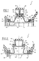
- a flatbed device is housed in the inside of a tire P without a tube and mounted on the rim 3 of a motor vehicle wheel equipped with the tire P.
- the basic structure of a flatbed device 1 consists of at least three coaxial and concentric parts that form a sandwich-like structure with a rigid inner annular portion 10, an intermediate annular portion 12 in a flexible or elastically deformable material and an annular portion rigid outer shell 14.
- the rigid inner portion 10 is hollow and formed of at least two rigid annular lateral flanges 16 and 18 which can be made of metal or a reinforced plastic material;
- the flexible intermediate portion 12 is formed by a continuous crown or discontinuous 20 rubber for example which is fixed between and at the periphery of the two flasks 16 and 18;
- the rigid outer portion 14 is fixed to the flexible ring 20 and its periphery forms the running surface flat on which can come to bear the tread of the tire P in run-flat configuration.
- the flatbed device 1 has been specially designed for removable flat rim in at least two parts, that is to say not having a rim (or “drop center” in English language), or wells delimited between the two rim flanges and two peripheral bosses (or “hump” in English) to house both internal and external heels of the tire.
- each flange 16 and 18 delimit, in half-cross section, a shape frustoconical flare outward towards the rim 3.
- the part radially internal of each flange 16 and 18 of the rigid inner part 10 has a peripheral groove 22 with a U-shaped cross section and which is delimited by an outer rim 24.
- the bottom of the groove 22 delimits the inner diameter of the flatbed device 1 on the one hand, and serves as contact surface with the rim 3 in flat tire running mode P on the other hand.
- annular bead 26 made of a material elastically deformable rubber (or “bead lock” in the tongue English) is attached to the outer peripheral surface of each rim 24 of the flanges 16 and 18 to ensure the locking in position of the heels Ti and Te of the Pneumatic P on the rim flanges.
- the ring 20 of the flexible intermediate portion 12 is fixed on the periphery and between the two flanges 16 and 18, knowing that this crown 20 may be discontinuous in the form of pads of a material elastomer for example, which are angularly regularly spaced.
- the rigid outer portion 14 has a straight half-section in T-shape with a central core constituted by an annular disk 30 with two flanges 32 at the periphery of the disk 30 to form the surface of flat rolling which may advantageously be coated with a flexible coating 34.
- the radially inner portion of the disk 30 is secured to the portion flexible intermediate 12. More specifically, the flexible intermediate ring 20 is formed of two series of pads 20a and 20b which are separated by the disc 30 and fixed by screwing or gluing, for example.
- the flatbed device can be made by molding to form a one-piece ring whose inside diameter is slightly greater than the diameter of the rim 3, this ring being then cut along a diametral plane passing through the axis flanges 16 and 18 to form two half-rings for questions of mounting on the rim.
- the flat rolling device 1 is mounted on the rim demountable plate 3 which has two parts 3a and 3b according to the example of the Figure 1.
- Part 3a of the rim 3 is a cylinder portion with, at a end, a peripheral rim or rim flange 40.
- Part 3b of the rim 3 is generally formed by a flange having a flange Perimeter or rim flange 42.
- the tire P is partially mounted passing that his internal heel Ti on the part 3a of the rim 3, we go up then successively inside the tire P the two half-rings of the rolling device 1 on the part 3a of the rim 3 on assemble the two half-rings to form a monobloc ring that one slides on the rim 3 in the direction of the internal heel Ti of the tire P of so that the bead 26 of the flange 18 comes into contact with the heel internal tire Ti to bring the latter substantially in contact with rim flange 40; we position the tire outer heel Te P in the vicinity of the bead 26 of the flange 16; we close the rim 3 in assembling the part 3b of the rim at its part 3a so as to wedge the heel outer Te between the rim flange 42 and the bead 26; and we put the Pneumatic pressure under pressure.
- the assembly of the two half-rings of the run 1 can be carried out by any appropriate device such at least two connecting plates fixed by screws for example, or any other device technically equivalent.
- a free annular space e is defined between the flanges 16 and 18, the ring 20 and the rim 3, this space e allowing the material of the ring 20 to work freely in shear during a flat run.
- the second embodiment illustrated in FIG. 2 essentially differs from that illustrated in Figure 1 by the shape of the two flanges 16 and 18, and the structure of the rigid outer portion 14. More precisely, the two flanges 16 and 18 delimit, in right half section, a frustoconical shape that flares outwardly from the rim 3, and the rigid outer part 14 of the flat-bed rolling device 1 is constituted by a annular box 45 half-cross section also trapezoidal shape, the large base forming the running surface flat.
- the crown flexible intermediate 20 is formed of two series of studs 20a and 20b fixed respectively between the side walls of the box 45 and the two flanges 16 and 18.
- the third embodiment illustrated in FIG. a variant of the second embodiment.
- the flanges 16 and 18 are substantially parallel
- the annular casing 45 which forms the outer part Rigid 14 is half-cross section of rectangular shape and no longer trapezoidal
- the flexible intermediate ring 12 of the rolling device plate 1 is formed of two series of studs 20a and 20b with presence of metal reinforcements that allow you to have the same flexibility while increasing the rigidity in horizontal compression. This rigidity allows especially to play on the degree of compression of the heels Ti and Te of the pneumatic on the rim flanges.
- the metal reinforcements are by example constituted by metal washers 47 embedded in the rubber and located in a plane substantially parallel to the flanges 16 and 18.
- the bottom of the grooves 22 of the rigid internal part 10 of the flat running device 1 comes locally in contact with the rim 3, this contact surface to be nevertheless enough not to damage the wheel.
- the fourth embodiment illustrated in FIG. 4 is a variant of the third embodiment where the two flanges 16 and 18 of the Rigid internal part 10 no longer have the flanges 24 delimiting the grooves 22.
- the flanges 16 and 18 are substantially planar and their ends radially internal are joined to each other by a cylindrical bottom discontinuous surrounding the rim 3 with a slight clearance, the bottom being continuous or constituted by rods 49 for example.
- the fifth embodiment illustrated in FIG. essentially the rigid inner part 10 of the flatbed device where the locking in position of the inner bead Ti of the tire P can be provided by a fastener ring 50 in one piece and at right half-section in V shape for example.
- the two wings of this clip 50 come respectively in frictional contact with the flange 18 and the internal bead Tire Ti P.
- the rigid outer portion 14 is constituted by an annular caisson 45 half-section right of generally rectangular shape, and the part flexible intermediate 12 is disposed in an inclined manner by giving it right half-section a frustoconical shape whose large base is located side of the rim 3.
- the frustoconical shape of the flexible intermediate portion 12 is deformed to take a globally cylindrical shape that gives the device flat rolling better holding under a materialized axial stress by the arrow F.
- the seventh embodiment illustrated in FIG. 7 is a variant of that illustrated in FIGS. 6 and 6a in order also to give the flat-bed rolling device 1 better resistance under axial stress in the flat-running configuration.
- the rigid outer annular portion 14 generally has a diabolo-shaped straight half-section which comprises a central core constituted by an annular disk 60 which is extended by two inner and outer hollow annular portions 62 and 62.
- the inner hollow portion 62 has a surface cylindrical peripheral 62a and two curved lateral surfaces 62b forming a circular arc.
- the outer hollow portion 64 has a cylindrical peripheral surface 64a, which may advantageously be coated with a flexible coating, and two curved lateral surfaces 64b forming a circular arc.
- the annular intermediate portion 12 has a frustoconical shape in a straight half-section whose large base is substantially in contact with the curved lateral surfaces 62b of the hollow inner portion 62, as illustrated on the upper half-view of FIG. 7.
- the hollow internal portion 62 forms a stop which penetrates into the space e of the rigid internal part 10 of the flat-bed runner device to come locally. in contact with the rim 3, and the annular intermediate portion 12 has deformed in order to take a straight frustoconical cross-section in opposite half-section to that of the upper half-view of FIG. 7, that is to say it comes into substantial contact with the curved lateral surfaces 64b of the outer hollow portion 64 of the rigid outer annular portion 14.
- FIGS. 8 and 8a an exemplary embodiment is illustrated. of the flexible intermediate portion 12 in a form developed to obtain also better holding under axial stress.
- the stops 70a and 70b are located at a distance from the central disc 30 and are intended to come into contact with said disc 30 for limit the lateral travel of the run-flat device, as is illustrated in Figure 8a, the stops 70 may provide a progressive action by playing on their thickness or height, so that the stops 70a or 70b do not simultaneously come into contact with the disk 30.
- the flexible intermediate portion 12 of the flatbed device is constituted by a crown or studs of a flexible elastomeric material like rubber for example which is able to work in shear in run-flat configuration.
- the flexible intermediate portion 12 is elastically deformable and consisting solely of metallic flexible elements 75a and 75b in the form for example springs.
- the flatbed device 1 consists of two similar cut parts 1a and 1b which are mounted head to tail.
- the radially outer ends of the two flanges 16 and 18 face each other to receive the flexible intermediate portion 12 of the flatbed device 1.
- the radially inner ends and two flanges 16 and 18 are interconnected by two walls lateral inclined so that the inner annular portion 10 delimits a space annular e which presents in a straight cross-section a frustoconical shape widening towards the rim 3.
- the rigid outer annular portion 14 is formed of two annular disks 82 whose peripheral edges extend by one side by two flanges 84 which define the running surface of the pneumatic in run-flat configuration.
- the two disks 82 contiguous against each other are fastened together by bolts 86 for example.
- the soft intermediate annular portion 12 consists of two series of studs 20a and 20b angularly spaced from each other, which are mounted between the radially outer ends of the two flanges 16 and 18 of the part rigid inner annulus 10 and the radially inner portions of both discs 82 of the rigid outer annular portion 14.
- the studs 20a and 20b are fixed by screws 88, knowing that the angular offset between the two series of pads 20a and 20b allows the passage of screws 88 through holes 88a pierced in the two contiguous discs 82.
- the two parts of the flanges 16 and 18 which form the surface device 80 of the rigid inner annular portion 10 are connected to each other. the other by a stapling device 90 for securing them in rotation.
- This stapling device 90 can be constituted by two series of fingers 90a and 90b that fit into each other.
- Two annular beads 26 are glued on both sides two flanges 16 and 18 to lock the positions of the heels Ti and Te of the tire P against the rim flanges 40 and 42.
- a shoe 92 forming a stop cushioning is attached to the radially inner ends of both 82 This pad 92 is intended to come into contact with the rim 3 in tire running configuration P.
- Such a shoe 92 can also be provided in the other embodiments.
- the technique of mounting the flatbed device which just described is the following.
- the two are pre-assembled separately parts 1a and 1b, the two parts 1a and 1b are introduced inside the pneumatic P after twisting twisted as this is schematically illustrated in FIG. 11, the two are assembled together parts 1a and 1b mounted upside down, the two parts are positioned assemblies 1a and 1b on the main half-rim 3a of the wheel, and we come then fix the secondary half rim 3b of the wheel to tighten the assembly.
Landscapes
- Engineering & Computer Science (AREA)
- Mechanical Engineering (AREA)
- Tires In General (AREA)
Applications Claiming Priority (2)
| Application Number | Priority Date | Filing Date | Title |
|---|---|---|---|
| FR0310738 | 2003-09-12 | ||
| FR0310738A FR2859662B1 (fr) | 2003-09-12 | 2003-09-12 | Methode pour alleger un dispositif de roulage a plat de roue de vehicule automobile et dispositif ainsi obtenu |
Publications (1)
| Publication Number | Publication Date |
|---|---|
| EP1514703A1 true EP1514703A1 (de) | 2005-03-16 |
Family
ID=34130801
Family Applications (1)
| Application Number | Title | Priority Date | Filing Date |
|---|---|---|---|
| EP04291856A Withdrawn EP1514703A1 (de) | 2003-09-12 | 2004-07-21 | Verfahren zur Erleichterung einer Notlaufvorrichtung für Kraftfahrzeugrad und Vorrichtung dadurch hergestellt |
Country Status (4)
| Country | Link |
|---|---|
| US (1) | US20050056355A1 (de) |
| EP (1) | EP1514703A1 (de) |
| CA (1) | CA2475417A1 (de) |
| FR (1) | FR2859662B1 (de) |
Cited By (5)
| Publication number | Priority date | Publication date | Assignee | Title |
|---|---|---|---|---|
| EP1897705A1 (de) * | 2006-09-12 | 2008-03-12 | Hutchinson | Runflat-Vorrichtung für Kraftfahrzeug und damit ausgestattete montierte Einheit |
| RU2572486C1 (ru) * | 2014-09-11 | 2016-01-10 | Открытое Акционерное Общество "Научно-Исследовательский Институт Стали" (Оао "Нии Стали") | Трехкольцевая колесная вставка безопасности |
| RU2622733C2 (ru) * | 2015-07-02 | 2017-06-19 | Общество с ограниченной ответственностью Научно-производственное предприятие "ПЛАСТИКОН" | Колесо |
| CN107921829A (zh) * | 2015-07-30 | 2018-04-17 | 欧洲塑料制造有限责任公司 | 应急插入件 |
| RU185564U1 (ru) * | 2018-10-04 | 2018-12-11 | Акционерное общество "Научно-исследовательский институт резиновых и полимерных изделий" | Эластичное распорное кольцо для шин |
Families Citing this family (2)
| Publication number | Priority date | Publication date | Assignee | Title |
|---|---|---|---|---|
| US9616717B2 (en) | 2013-06-27 | 2017-04-11 | Hutchinson, S.A. | Bead lock with wheel flange protection |
| CN115972813B (zh) * | 2022-12-15 | 2026-03-31 | 株洲九方装备股份有限公司 | 一种轨道车辆弹性车轮 |
Citations (2)
| Publication number | Priority date | Publication date | Assignee | Title |
|---|---|---|---|---|
| US4823854A (en) * | 1986-01-27 | 1989-04-25 | Motor Wheel Corporation | Safety tire and rim combination with safety insert |
| US5435363A (en) * | 1993-02-19 | 1995-07-25 | Pender; David R. | Run-flat pneumatic tires including plural separate inserts |
Family Cites Families (3)
| Publication number | Priority date | Publication date | Assignee | Title |
|---|---|---|---|---|
| US4281701A (en) * | 1980-02-15 | 1981-08-04 | W. R. Grace & Co. | Vehicle tire having run flat insert |
| US4709738A (en) * | 1986-02-14 | 1987-12-01 | Am General Corporation | Bead lock for pneumatic tires |
| US5479976A (en) * | 1994-12-20 | 1996-01-02 | Cho; Woon-Je | Three-chamber tire |
-
2003
- 2003-09-12 FR FR0310738A patent/FR2859662B1/fr not_active Expired - Lifetime
-
2004
- 2004-07-21 EP EP04291856A patent/EP1514703A1/de not_active Withdrawn
- 2004-07-26 CA CA002475417A patent/CA2475417A1/fr not_active Abandoned
- 2004-08-13 US US10/917,341 patent/US20050056355A1/en not_active Abandoned
Patent Citations (2)
| Publication number | Priority date | Publication date | Assignee | Title |
|---|---|---|---|---|
| US4823854A (en) * | 1986-01-27 | 1989-04-25 | Motor Wheel Corporation | Safety tire and rim combination with safety insert |
| US5435363A (en) * | 1993-02-19 | 1995-07-25 | Pender; David R. | Run-flat pneumatic tires including plural separate inserts |
Cited By (10)
| Publication number | Priority date | Publication date | Assignee | Title |
|---|---|---|---|---|
| EP1897705A1 (de) * | 2006-09-12 | 2008-03-12 | Hutchinson | Runflat-Vorrichtung für Kraftfahrzeug und damit ausgestattete montierte Einheit |
| FR2905631A1 (fr) * | 2006-09-12 | 2008-03-14 | Hutchinson Sa | Dispositif de roulage a plat pour vehicule automobile et ensemble monte l'incorporant. |
| EP1900551A1 (de) * | 2006-09-12 | 2008-03-19 | Hutchinson | Notlaufvorrichtung für ein Kraftfahrzeug und Aufbau mit der Notlaufvorrichtung |
| CN101386250B (zh) * | 2006-09-12 | 2010-09-01 | 哈特奇桑公司 | 一种用于机动车辆的缺气行驶装置及与之结合的车轮组件 |
| US7918255B2 (en) | 2006-09-12 | 2011-04-05 | Hutchinson | Run flat device for a motor vehicle, and a wheel assembly incorporating it |
| US7946324B2 (en) | 2006-09-12 | 2011-05-24 | Hutchinson | Run flat device for a motor vehicle, and a wheel assembly incorporating it |
| RU2572486C1 (ru) * | 2014-09-11 | 2016-01-10 | Открытое Акционерное Общество "Научно-Исследовательский Институт Стали" (Оао "Нии Стали") | Трехкольцевая колесная вставка безопасности |
| RU2622733C2 (ru) * | 2015-07-02 | 2017-06-19 | Общество с ограниченной ответственностью Научно-производственное предприятие "ПЛАСТИКОН" | Колесо |
| CN107921829A (zh) * | 2015-07-30 | 2018-04-17 | 欧洲塑料制造有限责任公司 | 应急插入件 |
| RU185564U1 (ru) * | 2018-10-04 | 2018-12-11 | Акционерное общество "Научно-исследовательский институт резиновых и полимерных изделий" | Эластичное распорное кольцо для шин |
Also Published As
| Publication number | Publication date |
|---|---|
| FR2859662B1 (fr) | 2005-12-02 |
| CA2475417A1 (fr) | 2005-03-12 |
| FR2859662A1 (fr) | 2005-03-18 |
| US20050056355A1 (en) | 2005-03-17 |
Similar Documents
| Publication | Publication Date | Title |
|---|---|---|
| EP1451023B1 (de) | Kraftfahrzeugradteller, insbesondere für personenkraftwagen | |
| EP1897705B1 (de) | Runflat-Vorrichtung für Kraftfahrzeug und damit ausgestattete montierte Einheit | |
| EP1453687B1 (de) | Scheibe eines kraftfahrzeugrades, insbesondere für einen personenkraftwagen | |
| FR2847202A1 (fr) | Fond de jante prevu pour equiper une jante de velo | |
| FR2898073A3 (fr) | Jante | |
| EP3017669B2 (de) | Verbessertes rad für landwirtschaftliche verwendung | |
| EP0956212B1 (de) | Notlaufvorrichtung für auto und verfahren zu seiner montage | |
| FR2698823A1 (fr) | Dispositif d'anneau perfectionné pour roulage à plat. | |
| EP0430743A1 (de) | Ringförmige Notlaufeinrichtung | |
| EP1514703A1 (de) | Verfahren zur Erleichterung einer Notlaufvorrichtung für Kraftfahrzeugrad und Vorrichtung dadurch hergestellt | |
| EP2269840A1 (de) | Pneumatischer Reifen für ein Rad | |
| FR2940770A1 (fr) | Dispositif de roulage a plat pour vehicule automobile et ensemble monte l'incorporant | |
| FR2853372A1 (fr) | Element de decouplage en materiau elastique et dispositif d'entrainement integrant un tel element dans un systeme de transmission de puissance | |
| FR2737267A1 (fr) | Friction d'embrayage, notamment pour vehicule automobile | |
| FR3050686B1 (fr) | Roue de vehicule automobile comportant un voile renforce par des materiaux composites | |
| FR2913369A3 (fr) | Jante, notamment pour bicyclettes, et son procede de fabrication | |
| EP4351891B1 (de) | Expander mit verbesserter konstruktion und rollende anordnung mit solch einem expander | |
| EP1538007B1 (de) | Notlaufvorrichtung für Kraftfahrzeug und diese enthaltende Radeinheit | |
| FR2825319A1 (fr) | Procede de construction d'une roue a rayons sous tension et roue a rayons sous tension destinee a un vehicule a deux roues | |
| FR2879126A1 (fr) | Roue allegee en particulier pour machines agricoles | |
| EP1190873A1 (de) | Notlauf-System für ein Kraftfahrzeug | |
| EP1650056A1 (de) | Reifenwulstspreizring | |
| WO2016151210A1 (fr) | Enjoliveur de roue de véhicule automobile comportant des bourrelets de protection en plastique souple | |
| FR3130199A1 (fr) | Extenseur a stylisme ameliore et ensemble roulant comportant un tel extenseur | |
| WO2022234197A1 (fr) | Suspente de ligne d'echappement d'un vehicule |
Legal Events
| Date | Code | Title | Description |
|---|---|---|---|
| PUAI | Public reference made under article 153(3) epc to a published international application that has entered the european phase |
Free format text: ORIGINAL CODE: 0009012 |
|
| AK | Designated contracting states |
Kind code of ref document: A1 Designated state(s): AT BE BG CH CY CZ DE DK EE ES FI FR GB GR HU IE IT LI LU MC NL PL PT RO SE SI SK TR |
|
| AX | Request for extension of the european patent |
Extension state: AL HR LT LV MK |
|
| 17P | Request for examination filed |
Effective date: 20050725 |
|
| AKX | Designation fees paid |
Designated state(s): DE FR GB IT |
|
| GRAP | Despatch of communication of intention to grant a patent |
Free format text: ORIGINAL CODE: EPIDOSNIGR1 |
|
| STAA | Information on the status of an ep patent application or granted ep patent |
Free format text: STATUS: THE APPLICATION IS DEEMED TO BE WITHDRAWN |
|
| 18D | Application deemed to be withdrawn |
Effective date: 20061005 |