EP1514763A1 - Lenksäulenmodul mit einzigem Wegsensor - Google Patents
Lenksäulenmodul mit einzigem Wegsensor Download PDFInfo
- Publication number
- EP1514763A1 EP1514763A1 EP04292134A EP04292134A EP1514763A1 EP 1514763 A1 EP1514763 A1 EP 1514763A1 EP 04292134 A EP04292134 A EP 04292134A EP 04292134 A EP04292134 A EP 04292134A EP 1514763 A1 EP1514763 A1 EP 1514763A1
- Authority
- EP
- European Patent Office
- Prior art keywords
- steering column
- module
- axial
- adjustment
- motor
- Prior art date
- Legal status (The legal status is an assumption and is not a legal conclusion. Google has not performed a legal analysis and makes no representation as to the accuracy of the status listed.)
- Granted
Links
Images




Classifications
-
- B—PERFORMING OPERATIONS; TRANSPORTING
- B62—LAND VEHICLES FOR TRAVELLING OTHERWISE THAN ON RAILS
- B62D—MOTOR VEHICLES; TRAILERS
- B62D1/00—Steering controls, i.e. means for initiating a change of direction of the vehicle
- B62D1/02—Steering controls, i.e. means for initiating a change of direction of the vehicle vehicle-mounted
- B62D1/16—Steering columns
- B62D1/18—Steering columns yieldable or adjustable, e.g. tiltable
- B62D1/181—Steering columns yieldable or adjustable, e.g. tiltable with power actuated adjustment, e.g. with position memory
Definitions
- Patent DE10144476A1 relates to a unit of steering column of a motor vehicle comprising a steering column with adjustable length and / or tilt electromechanically.
- the object of the invention is to design a unit of this type that can be easily adapted to different types of vehicles, which can be reconfigured in a variable way vis-à-vis its functionality, right from the manufacturing process, and that is clearly delineated from the other structural units of the motor vehicle.
- the column unit of motor vehicle steering of the invention comprises, in addition to the mechanical elements and adjustment members, necessary for steering control and modification electrical position of the steering column, at less a drive system, a control unit to produce control signals for to the drive system (s) and electrical components of adjustment, as well as connections intended to connect the unit to the onboard network.
- German patent DE19641152 discloses a steering column unit for motor vehicle comprising a column housing of direction and an actuating device electrically, used to perform the longitudinal adjustment and tilt adjustment of the steering column.
- the adjusting device carries a drive unit electrical to rotate a setting pin and to move longitudinally and tilt at least respectively a setting mechanism.
- a switching device ensures the clutching or disengagement of a spindle nut arranged in the vicinity of this device.
- European Patent EP0461025 discloses a motorized position adjustment control device a steering column adjustable in depth and tilt where the steering column includes a tree made of an end section intended to carry a steering wheel and an expandable or retractable spacer consisting of two parts assembled by a junction sliding gimbals, connecting gimbals sections.
- This device of the prior art comprises a fixed body connected to the vehicle and a movable body constituted sliding element relative to the fixed body and a tilting element relative to the sliding element using an articulation of axis (Y) orthogonal to the axis (X) of the column, as well as bearings supporting the shaft in the moving body.
- a transmission associated with an engine single has an input connected to the motor and two outputs so that one of the outputs causes the translation and the other output causes inclination. Both outputs are activated at related relative speeds for ensure the depth adjustment of the two body elements mobile and tree sections they carry. Only one outputs is activated to ensure the setting in Tilting tilting element and shaft section he wears.
- the fixed body and the mobile body constitute a sheath, the mobile body sliding in the fixed body in the axial direction.
- the PCT patent W003022657 of the NACAM GmbH offers a column unit of direction further comprising mechanical elements and adjusting elements, necessary for steering control and the electrical modification of the position of the steering column, at least one drive system, an electronic control unit to produce control signals for the system (s) drive and to the electrical control devices, as well as connections to connect the unit to the network of edge.
- German patent DE3311229 describing a setting device using a motor not step by step brushless type controlled by trains pulse. Such a solution is not satisfactory because in the event of mechanical maladjustment of the mechanism of training, for example due to wear or limit overrun, positioning control is wrong.
- the purpose of the present invention is to propose a simplified solution for acquiring settings and control of the memorization and the restitution of a setting selected by a driver.
- the invention relates to most general meaning a column module of direction with motorized positioning control comprising a single motor for adjusting the steering wheel position a transverse pivot axis for the adjustment of the inclination of the steering wheel on the one hand, and along an axis longitudinal for the depth adjustment on the other hand, said motor causing the displacement of a first element threaded connection providing a first adjustment mechanism according to one of said axes, and a second element of threaded connection resulting in a second adjustment mechanism according to at least the other of said axis, said module comprising a controller for storing at least one position of reference along said two axes and for the comparison between a reference position and the actual position along said two axes, characterized in that said engine single drives a single incremental position sensor delivering a position signal to said controller and thereby that said controller receives further information representative of the state of at least one of said elements junction.
- This unique incremental sensor can be either directly on the engine, either on any element of the transmission, even on the output axis.
- This state can be “engaged” or “disengaged” when the joining element comprises a clutch, or “active” or “inactive” in the case of a two-engine output axes of which one or the other is driven.
- Information on the condition of the connecting elements comes from the control circuit that controls the operation of the adjustment mechanism.
- the advantage of this system is to have only one only relative sensor needed for all functions positioning the column along the two axes.
- This sensor is also easily integrated in the motor or on an element of the transmission that drives the setting, thus decreasing the number of components needed on the column and also simplifying the wiring necessary.
- one of the elements junction causes the axial displacement in translation of the steering column with respect to the fixed part of the module
- the other connecting element causes the rotation of the steering column with respect to an axis of transverse pivoting of the steering column by relative to the fixed part of the module, each of those elements junction cooperating with a single threaded screw driven by said single engine
- the module comprising means for control of the clutch of at least one of the elements of junction with said threaded screw, said means for command delivering said activation information corresponding to the state of said clutches.
- one of the elements junction is in permanent engagement with said screw driven by the single engine.
- the controller has a first memory register incremented according to the incremental sensor variations only when the clutch of the first joining means is activated, and a second memory register incremented according to the variations of said incremental sensor permanently.
- said pivot is located on the side of the steering column and the fixed part closest to the steering wheel.
- said pivot is located on the side of the steering column and the fixed part farthest from the steering wheel.
- the module advantageously comprises detectors of the position of the junction elements with respect to a position of reference, delivering a reset signal of said memory registers.
- detectors can be example of micro-switches, an optical detector, magnetic, inductive or capacitive, etc.
- each of the elements of junction is coupled via a clutch with said screw driven by the single motor and in that the controller has a first memory register incremented according to sensor variations incremental when the clutch of the first means of junction is activated, and a second memory register incremented according to the variations of said sensor incremental when the clutch of the second means of junction is enabled.
- the module comprises detectors of the position of the connecting elements by referred to a reference position, each of those sensors delivering a reset signal of one said memory registers.
- the single engine has two output axes and a means of switching ensuring the selection of one or the other said axes or both axes simultaneously.
- One of the connecting elements cooperates with a screw-nut connection with one of the output pins for to cause the axial displacement in translation of the column direction relative to the fixed part of the module, and the other of the connecting elements cooperating by a connection screw-nut with the other output shaft to drive the rotation of the steering column with respect to an axis of transverse pivoting of the steering column by relative to the fixed part of the module, the module comprising switching means delivering said information activation corresponding to the state of said output axes.
- the invention also relates to a controller for a module according to at least one of the claims preceding characterized in that it comprises a first register incremented by the pulses delivered by said incremental sensor driven by the single motor when axial adjustment is selected, and a second register incremented by the pulses delivered by said sensor incremental driven by the single motor when a setting tilt is selected.
- the first register is reset by a signal delivered by a first detector when the axial joining element is in a position reference
- a second register is reset by a signal delivered by a second detector when the radial joining element is in a position of reference.
- the controller comprises a first register incremented by the pulses delivered by said incremental sensor driven by the single motor when a setting according to one of the adjustment modes is selected, and a second register incremented by pulses delivered by said incremental sensor driven by the single engine.
- said registers are reset by two signals delivered by detectors when the two connecting elements are each in reference position.
- detectors can be example of micro-switches, an optical detector, magnetic, inductive or capacitive, etc.
- the invention can be implemented under different forms of common characteristic of motorization by an engine unique, with a single incremental sensor on the engine or an element of the transmission.
- the control of the setting of position of a single-engine column uses only one relative cyclic sensor for example an effect probe Hall, or an optical or magnetic sensor that delivers a information of rotation of the engine which drives the exit screw on which or which move the junctions that provide axial or angular adjustment.
- the number of cycles given by this sensor per motor revolution is variable from one column to another, and this report from transmission must be taken into account in the description below.
- the controller has a counting system (C) pulses delivered by this sensor. These impulses are counted in a direction of rotation of the motor, counted in the other direction of rotation. According to the axis of selected setting, these pulses are to be considered either for the measurement of axial displacement, ie for the measurement of radial displacement.
- C counting system
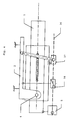
- FIG. 1 represents a schematic view of a example module with axial and radial settings independent, with one motor and two clutches.
- the module described with reference to FIG. has a steering column (1) movable in two axes with respect to a fixed part (2) intended to ensure the connection of the module with the passenger compartment of the vehicle automobile.
- the steering column (1) is movable in translation with respect to a sleeve (3) integral with the fixed part (2).
- This sheath (3) is rotatable around a transverse axis (4) perpendicular to the plane vertical passing through the axis of the steering column (1).
- This axis (4) is arranged on the opposite side to the end of the column on which is mounted the steering wheel.
- the switchover sleeve (3) with respect to this axis (4) ensures the adjustment in height of the steering wheel, and a slight modification of the tilt of the steering wheel.
- the module has a single motor (5) driving a worm (6) parallel to the axis longitudinal direction of the steering column (1).
- the first joining element (7) ensures the tilting movement of the sheath (3) relative to the fixed part (2). It includes for this purpose a connecting rod (9) one end of which is articulated on the joining element (7) and the other end is articulated with respect to an axis connecting with the fixed part (2).
- the displacement of the first joining element (7) along the worm (6) changes the formed angle by this rod (9) with the longitudinal axis, and therefore the transverse spacing of the connection point (10) with the axis of the steering column (1), and therefore the angle formed by the axis of the steering column (1) with the fixed part (2) and the height position of the wheel.
- the displacement of the first joining element (7) ensures the angular displacement of the column of direction (1), for steering height adjustment. he is not driven permanently by the screw (6), but cooperates with it by means of a clutch.
- the connecting element (7) When the connecting element (7) is in engaged condition, it provides angular adjustment of the steering column (1): whenever the engine is running in one direction or in the other, the connecting element (7) is moved in translation in one direction or the other, and the position angle of the steering column (1) is modified by relative to the fixed part (2).
- this connecting element does not not move even if the screw (6) is rotating.
- the displacement of the second joining element (8) ensures the axial displacement of the steering column (1), for the depth adjustment of the steering wheel. He is not driven permanently by the screw (6), but cooperates with this one by means of a clutch.
- the connecting element (8) When the connecting element (8) is in engaged condition, it ensures the axial adjustment of the steering column (1): each time that the engine turns in one direction or the other, the joining element (8) is displaced in translation in one way or the other, and the axial position of the steering column (1) is amended.
- this joining element does not move even if the screw (6) is rotating.
- the motor (5) is coupled directly or indirectly to a sensor relative to Hall Probe delivering a pulse at each rotation step.
- the controller includes two counters.
- a first counter receives pulses from the sensor relative, and is incremented or decremented according to the signal of direction of rotation whenever the engine drives the screw (6) and that the second joining element (8) is engaged.
- the state of this first counter corresponds to the axial position of the steering column.
- the second meter also receives the pulses from the relative sensor, and is incremented or decremented according to the direction of rotation signal each time the motor drives the screw (6) and that the first joining element (7) is in the engaged state.
- the state of this second counter corresponds to the position angular of the steering column.
- This counter (20) is incremented at each impulse received on the second input, when the first input receives a signal corresponding to the engaged state, and when the third input receives a corresponding signal at a first direction of rotation.
- This counter (20) is decremented at each impulse received on the second input, when the first input receives a signal corresponding to the engaged state, and when the third input receives a corresponding signal to a reverse direction of rotation.
- This counter (20) is maintained in its state previous in other cases.
- This counter (30) is incremented at each impulse received on the second input, when the first input receives a signal corresponding to the engaged state, and when the third input receives a corresponding signal at a first direction of rotation.
- This counter (30) is decremented at each impulse received on the second input, when the first input receives a signal corresponding to the engaged state, and when the third input receives a corresponding signal to a reverse direction of rotation.
- This counter (30) is maintained in its state previous in other cases.
- the circuit also includes, for each of the two counters, as a variant a receiving input the information corresponding to the motor output axis selected (instead of the inputs of each of the inputs receiving a signal corresponding to the state of the clutch).
- Each of the counters (20, 30) is connected to a memory register (21, 31) for the recording of pairs of positions by a driver. These couples of positions allow the driver who registered them to regain your favorite position.
- the return of a pre-registered position is done using two comparators (22, 32), the first controlling the clutch of the second joining element (8) when the axial position measured by the first counter (20) corresponds to the prerecorded position in the first register (21), and the second comparator controlling the clutch of the first joining element (7) when the measured radial position by the second counter (30) corresponds to the position prerecorded in the second register (31).
- the processing of information by the calculator can give rise to various variants.
- FIG. 3 represents a schematic view of a example module with axial and radial settings independent, with a motor with two output axes, one of which only one is rotating at a time.
- the motor (5) drives two screws (27, 28) via a switching mechanism ensuring the drive of the screw (27) or (exclusive) of the screw (28).
- the motor (5) is coupled directly or indirectly to a single relative sensor delivering a signal transmitted to the controller.
- the position counter radial is incremented or decremented in the sense of rotation of the motor (5) when the screw (27) the joining element (17) is active.
- FIG. 4 represents a schematic view of a second example module with axial and independent radial, with a movable motor, a clutch fixed and a permanent nut.
- the single motor (5) is not fixed with respect to the cockpit, but secured to the mobile column (1) with which he moves.
- the motor (5) drives a screw (36) parallel to the steering column (1) driving by a screw-nut connection permanently a first joining element (37) actuating a connecting rod whose opposite end is connected to the fixed part (2) by a transverse articulation. he provides pivoting adjustment of the steering wheel.
- This screw (36) also results in a disengageable screw-nut connection a second element of junction (38) connected to the fixed part (2). It ensures the depth adjustment of the steering wheel.
- a single relative sensor is coupled directly or indirectly to the motor and delivers impulses to two counters, one incremented and decremented at each rotation of the motor, and the other when the second element junction (38) is engaged.
- FIG. 5 represents a schematic view of a example module with axial and radial settings interdependent with motor, clutch and nut permanent.
- the steering column (1) presents to its end nearest the steering wheel pivot (52) allowing the inclination of a plate (51) which comprises the part upper axis of the steering column on which will be mounted the steering wheel.
- the steering column (1) is sliding axially relative to a sheath (50).
- a single electric motor (5) ensures the training of a screw with which cooperate a first connecting element (54) disengageable ensuring the axial displacement of the column direction (1) relative to the fixed sheath (50), and a second joining element (55) permanently engaged by a screw-nut connection.
- This second connecting element (55) actuates a connecting rod (56) cooperating with the plate (51) by through a joint.
- a single relative sensor is coupled directly or indirectly with the motor, to deliver impulses to a first incremented axial position counter or decremented only when the joining element (54) is engaged and to a second incremented position counter or decremented permanently.
- the first counter receives the pulses from the relative sensor, and is incremented or decremented according to the direction of rotation signal each the motor drives the screw (56) and that the first junction element (54) is in the engaged state.
- the state of this first counter corresponds to the axial position of the steering column.
- the second meter also receives the pulses from the relative sensor, and is incremented or decremented according to the direction of rotation signal each time the motor drives the screw (56).
- the position angular of the column corresponds to the state of this second counter to which the first counter is subtracted.
- the resetting of the counters is done using reference position detectors.
- Figure 6 shows a schematic view of a second example module with axial and interdependent radial with a motor with two output axes (or only the axis (65) rotates for radial adjustment, or both rotate at the same speed for axial adjustment).
- This version corresponds to a realization implementing a single motor (5) driving two output shafts (64, 65).
- the first axis (64) causes the joining element (54) ensuring the axial displacement of the column of direction (1).
- the second axis (65) causes the element of junction (55) ensuring the orientation of the plate (51).
- Counters can deliver either an image respectively of the axial position and the position radial, respectively an image of one of its two positions and a picture of the combination of the two positions. In the latter case, the corresponding information at the other position is determined by subtraction between the content of the two meters.
- the different counting modes can be present as follows.
Landscapes
- Engineering & Computer Science (AREA)
- Chemical & Material Sciences (AREA)
- Combustion & Propulsion (AREA)
- Transportation (AREA)
- Mechanical Engineering (AREA)
- Steering Controls (AREA)
- Arrangement Or Mounting Of Control Devices For Change-Speed Gearing (AREA)
- Reciprocating, Oscillating Or Vibrating Motors (AREA)
- Power Steering Mechanism (AREA)
- Air Bags (AREA)
Applications Claiming Priority (2)
| Application Number | Priority Date | Filing Date | Title |
|---|---|---|---|
| FR0310602 | 2003-09-09 | ||
| FR0310602A FR2859438B1 (fr) | 2003-09-09 | 2003-09-09 | Colonnes de direction destinees a des vehicules automobiles |
Publications (2)
| Publication Number | Publication Date |
|---|---|
| EP1514763A1 true EP1514763A1 (de) | 2005-03-16 |
| EP1514763B1 EP1514763B1 (de) | 2006-11-22 |
Family
ID=34130770
Family Applications (1)
| Application Number | Title | Priority Date | Filing Date |
|---|---|---|---|
| EP04292134A Expired - Lifetime EP1514763B1 (de) | 2003-09-09 | 2004-09-03 | Lenksäulenmodul mit einzigem Wegsensor |
Country Status (7)
| Country | Link |
|---|---|
| US (1) | US20050050979A1 (de) |
| EP (1) | EP1514763B1 (de) |
| JP (1) | JP4901084B2 (de) |
| AT (1) | ATE345966T1 (de) |
| AU (1) | AU2004205177B2 (de) |
| DE (1) | DE602004003314T2 (de) |
| FR (1) | FR2859438B1 (de) |
Families Citing this family (13)
| Publication number | Priority date | Publication date | Assignee | Title |
|---|---|---|---|---|
| US7216562B2 (en) * | 2004-06-07 | 2007-05-15 | Thyssenkrupp Presta Ag | Electrically adjustable steering column and operating method thereof |
| US20060283281A1 (en) * | 2005-06-20 | 2006-12-21 | Xiaoyu Li | Synchronized screw driven power telescoping and tilt mechanism for steering column |
| JP5125253B2 (ja) * | 2007-06-26 | 2013-01-23 | アイシン精機株式会社 | 車両のステアリング装置 |
| DE102012101375A1 (de) * | 2012-02-21 | 2013-08-22 | Zf Lenksysteme Gmbh | Höhenverstellvorrichtung für eine Lenksäule |
| DE102018212738A1 (de) * | 2018-07-31 | 2020-02-06 | Brose Fahrzeugteile Gmbh & Co. Kommanditgesellschaft, Coburg | Elektromotorisch verstellbare Lenkvorrichtung |
| DE102019201390A1 (de) | 2019-02-04 | 2020-08-06 | Thyssenkrupp Ag | Lenksäule für ein Kraftfahrzeug |
| DE102019004840A1 (de) * | 2019-07-12 | 2021-01-14 | Thyssenkrupp Ag | Verfahren zum Betreiben einer motorisch verstellbaren Lenksäule und motorisch verstellbare Lenksäule für ein Kraftfahrzeug |
| FR3099455B1 (fr) | 2019-07-31 | 2021-07-16 | Psa Automobiles Sa | Dispositif de direction par fils a volant escamotable pour vehicules automobiles |
| KR102474860B1 (ko) * | 2021-04-20 | 2022-12-06 | 디와이씨스 주식회사 | 스티어링휠 제어장치 및 그 제어방법 |
| CN114435284A (zh) * | 2022-02-14 | 2022-05-06 | 苏州迪非电子有限公司 | 一种具有自动记忆功能的新能源客车方向盘移动机构 |
| DE102023105590A1 (de) | 2023-03-07 | 2024-09-12 | Ford Global Technologies Llc | Fahrzeug mit Lenkrad, das in eine Nichtlenkposition überführbar ist |
| CN116279752A (zh) * | 2023-04-28 | 2023-06-23 | 重庆长安汽车股份有限公司 | 一种电动调节转向柱、方向盘的控制方法及车辆 |
| BE1032071B1 (de) * | 2023-10-18 | 2025-05-19 | Thyssenkrupp Presta Ag | Verfahren zum Betreiben eines Verstellantriebs einer motorisch verstellbaren Lenksäule, Steuereinheit, Lenksäule und Kraftfahrzeug |
Citations (5)
| Publication number | Priority date | Publication date | Assignee | Title |
|---|---|---|---|---|
| DE3311229A1 (de) * | 1983-03-28 | 1984-10-04 | Vdo Adolf Schindling Ag, 6000 Frankfurt | Einrichtung zum verstellen eines gegenstandes in fahrzeugen, insbesondere eines rueckspiegels |
| EP0461025A1 (de) * | 1990-06-07 | 1991-12-11 | Nacam | Einstellvorrichtung des Standes einer verstellbarer Lenksäule |
| DE4217664A1 (de) * | 1991-06-03 | 1992-12-10 | Mccord Winn Textron Inc | Kraftantrieb fuer einen einstellbaren mechanismus |
| WO2001081149A2 (de) * | 2000-04-20 | 2001-11-01 | Thyssenkrupp Presta Aktiengesellschaft | Verstell- und fixiereinrichtung für eine höhen- und/oder längenverstellbare lenkwelle |
| WO2003022657A2 (de) * | 2001-09-10 | 2003-03-20 | Nacam Deutschland Gmbh | Kraftfahrzeuglenksäuleneinheit mit verstellbarer lenksäule |
Family Cites Families (5)
| Publication number | Priority date | Publication date | Assignee | Title |
|---|---|---|---|---|
| GB1362156A (en) * | 1972-07-12 | 1974-07-30 | Furuno Electric Co | Digitally controlled recording device |
| JPS5675224A (en) * | 1979-11-21 | 1981-06-22 | Nissan Motor Co Ltd | Automatic selector for sheet position |
| US4698569A (en) * | 1985-06-13 | 1987-10-06 | Yoshikazu Kimura | Apparatus for locating a carrier at a desired position |
| JPH03262756A (ja) * | 1990-03-14 | 1991-11-22 | Mitsubishi Motors Corp | 連動機能を有する車両用運転装備 |
| JP3579589B2 (ja) * | 1998-06-30 | 2004-10-20 | シャープ株式会社 | ステープル装置 |
-
2003
- 2003-09-09 FR FR0310602A patent/FR2859438B1/fr not_active Expired - Lifetime
-
2004
- 2004-08-23 US US10/923,912 patent/US20050050979A1/en not_active Abandoned
- 2004-08-23 AU AU2004205177A patent/AU2004205177B2/en not_active Ceased
- 2004-09-03 AT AT04292134T patent/ATE345966T1/de not_active IP Right Cessation
- 2004-09-03 DE DE602004003314T patent/DE602004003314T2/de not_active Expired - Lifetime
- 2004-09-03 EP EP04292134A patent/EP1514763B1/de not_active Expired - Lifetime
- 2004-09-08 JP JP2004260703A patent/JP4901084B2/ja not_active Expired - Fee Related
Patent Citations (5)
| Publication number | Priority date | Publication date | Assignee | Title |
|---|---|---|---|---|
| DE3311229A1 (de) * | 1983-03-28 | 1984-10-04 | Vdo Adolf Schindling Ag, 6000 Frankfurt | Einrichtung zum verstellen eines gegenstandes in fahrzeugen, insbesondere eines rueckspiegels |
| EP0461025A1 (de) * | 1990-06-07 | 1991-12-11 | Nacam | Einstellvorrichtung des Standes einer verstellbarer Lenksäule |
| DE4217664A1 (de) * | 1991-06-03 | 1992-12-10 | Mccord Winn Textron Inc | Kraftantrieb fuer einen einstellbaren mechanismus |
| WO2001081149A2 (de) * | 2000-04-20 | 2001-11-01 | Thyssenkrupp Presta Aktiengesellschaft | Verstell- und fixiereinrichtung für eine höhen- und/oder längenverstellbare lenkwelle |
| WO2003022657A2 (de) * | 2001-09-10 | 2003-03-20 | Nacam Deutschland Gmbh | Kraftfahrzeuglenksäuleneinheit mit verstellbarer lenksäule |
Also Published As
| Publication number | Publication date |
|---|---|
| JP4901084B2 (ja) | 2012-03-21 |
| AU2004205177A1 (en) | 2005-03-24 |
| EP1514763B1 (de) | 2006-11-22 |
| FR2859438A1 (fr) | 2005-03-11 |
| AU2004205177B2 (en) | 2010-11-04 |
| US20050050979A1 (en) | 2005-03-10 |
| JP2005082148A (ja) | 2005-03-31 |
| ATE345966T1 (de) | 2006-12-15 |
| DE602004003314D1 (de) | 2007-01-04 |
| DE602004003314T2 (de) | 2007-07-05 |
| FR2859438B1 (fr) | 2006-02-03 |
Similar Documents
| Publication | Publication Date | Title |
|---|---|---|
| EP1514763B1 (de) | Lenksäulenmodul mit einzigem Wegsensor | |
| FR2635491A1 (fr) | Retroviseur exterieur pour vehicule | |
| EP2112406B1 (de) | Vorrichtung zur Positionserkennung eines Steuerhebels des Getriebes eines Kraftfahrzeugs | |
| FR3048394A1 (fr) | Ecran orientable a deux axes motorises pour planche de bord automobile | |
| EP2900515B1 (de) | Steuermodul | |
| EP3744904B1 (de) | Antikollisionssystem für baustellenmaschine, und baustellenmaschine, die mit einem solchen antikollisionssystem ausgestattet ist | |
| EP0816795B1 (de) | Längen- oder Winkelmessinstrument | |
| EP1205133B1 (de) | Betätigungsvorrichtung für ein Sitzelement und damit versehener Sitz | |
| FR2866843A1 (fr) | Systeme de siege d'automobile comportant un dispositif de mesure de l'inclinaison du dossier | |
| WO2007101955A2 (fr) | Dispositif de retroviseur pour vehicule automobile | |
| EP0522924A1 (de) | Drehantrieb zur Erzeugung eines durch adaptierbare Steuerkennlinien veränderbaren Drehmoments am Steuerrad eines Steuersystems | |
| WO2013140093A1 (fr) | Dispositif de detection des positions p, r, n, d, m+, m et m- d'un levier de commande d'une boite de vitesses d'un vehicule automobile. | |
| EP0490734A1 (de) | Verfahren und Vorrichtung zur selbsttätigen Einstellung einer reflektierenden Fläche | |
| EP1772649B1 (de) | Schalthebel für Getriebe | |
| FR3073472A1 (fr) | Dispositif de detection de position d'un siege par rapport au chassis d'un vehicule | |
| FR3107483A1 (fr) | Vehicule avec retrovision numerique a affichage reglable | |
| EP3829929A1 (de) | Rückblickvideovorrichtung für kraftfahrzeug | |
| FR2552387A1 (fr) | Commande assistee de direction en particulier pour vehicules automobiles | |
| FR2578046A1 (fr) | Dispositif et procede de mesure de l'angle forme entre les deux elements d'un vehicule articule, et son application a l'orientation automatique d'un retroviseur exterieur | |
| FR3043048A1 (fr) | Volant de direction ergonomique pour vehicule automobile et systeme de commande de direction comportant un tel volant | |
| FR3091215A1 (fr) | Système d’actionneurs synchronisés pour siège de véhicule | |
| EP3418852B1 (de) | Steuervorrichtung und lenkrad, das mit einer solchen vorrichtung ausgestattet ist, insbesondere für kraftfahrzeug | |
| FR3110237A1 (fr) | Colonne de direction equipee d’un dispositif de detection des efforts appliques sur le volant | |
| WO1994026552A1 (fr) | Dispositif de commande de positions d'axes de deplacement | |
| FR3161906A1 (fr) | Machine de manutention équipée d’un système de détection de données d’environnement, et kit de détection correspondant |
Legal Events
| Date | Code | Title | Description |
|---|---|---|---|
| PUAI | Public reference made under article 153(3) epc to a published international application that has entered the european phase |
Free format text: ORIGINAL CODE: 0009012 |
|
| AK | Designated contracting states |
Kind code of ref document: A1 Designated state(s): AT BE BG CH CY CZ DE DK EE ES FI FR GB GR HU IE IT LI LU MC NL PL PT RO SE SI SK TR |
|
| AX | Request for extension of the european patent |
Extension state: AL HR LT LV MK |
|
| 17P | Request for examination filed |
Effective date: 20050420 |
|
| AKX | Designation fees paid |
Designated state(s): AT BE BG CH CY CZ DE DK EE ES FI FR GB GR HU IE IT LI LU MC NL PL PT RO SE SI SK TR |
|
| GRAP | Despatch of communication of intention to grant a patent |
Free format text: ORIGINAL CODE: EPIDOSNIGR1 |
|
| GRAS | Grant fee paid |
Free format text: ORIGINAL CODE: EPIDOSNIGR3 |
|
| GRAA | (expected) grant |
Free format text: ORIGINAL CODE: 0009210 |
|
| AK | Designated contracting states |
Kind code of ref document: B1 Designated state(s): AT BE BG CH CY CZ DE DK EE ES FI FR GB GR HU IE IT LI LU MC NL PL PT RO SE SI SK TR |
|
| PG25 | Lapsed in a contracting state [announced via postgrant information from national office to epo] |
Ref country code: RO Free format text: LAPSE BECAUSE OF FAILURE TO SUBMIT A TRANSLATION OF THE DESCRIPTION OR TO PAY THE FEE WITHIN THE PRESCRIBED TIME-LIMIT Effective date: 20061122 Ref country code: PL Free format text: LAPSE BECAUSE OF FAILURE TO SUBMIT A TRANSLATION OF THE DESCRIPTION OR TO PAY THE FEE WITHIN THE PRESCRIBED TIME-LIMIT Effective date: 20061122 Ref country code: FI Free format text: LAPSE BECAUSE OF FAILURE TO SUBMIT A TRANSLATION OF THE DESCRIPTION OR TO PAY THE FEE WITHIN THE PRESCRIBED TIME-LIMIT Effective date: 20061122 Ref country code: AT Free format text: LAPSE BECAUSE OF FAILURE TO SUBMIT A TRANSLATION OF THE DESCRIPTION OR TO PAY THE FEE WITHIN THE PRESCRIBED TIME-LIMIT Effective date: 20061122 Ref country code: IT Free format text: LAPSE BECAUSE OF FAILURE TO SUBMIT A TRANSLATION OF THE DESCRIPTION OR TO PAY THE FEE WITHIN THE PRESCRIBED TIME-LIMIT;WARNING: LAPSES OF ITALIAN PATENTS WITH EFFECTIVE DATE BEFORE 2007 MAY HAVE OCCURRED AT ANY TIME BEFORE 2007. THE CORRECT EFFECTIVE DATE MAY BE DIFFERENT FROM THE ONE RECORDED. Effective date: 20061122 Ref country code: CZ Free format text: LAPSE BECAUSE OF FAILURE TO SUBMIT A TRANSLATION OF THE DESCRIPTION OR TO PAY THE FEE WITHIN THE PRESCRIBED TIME-LIMIT Effective date: 20061122 Ref country code: NL Free format text: LAPSE BECAUSE OF FAILURE TO SUBMIT A TRANSLATION OF THE DESCRIPTION OR TO PAY THE FEE WITHIN THE PRESCRIBED TIME-LIMIT Effective date: 20061122 Ref country code: IE Free format text: LAPSE BECAUSE OF FAILURE TO SUBMIT A TRANSLATION OF THE DESCRIPTION OR TO PAY THE FEE WITHIN THE PRESCRIBED TIME-LIMIT Effective date: 20061122 Ref country code: SK Free format text: LAPSE BECAUSE OF FAILURE TO SUBMIT A TRANSLATION OF THE DESCRIPTION OR TO PAY THE FEE WITHIN THE PRESCRIBED TIME-LIMIT Effective date: 20061122 Ref country code: SI Free format text: LAPSE BECAUSE OF FAILURE TO SUBMIT A TRANSLATION OF THE DESCRIPTION OR TO PAY THE FEE WITHIN THE PRESCRIBED TIME-LIMIT Effective date: 20061122 |
|
| REG | Reference to a national code |
Ref country code: GB Ref legal event code: FG4D Free format text: NOT ENGLISH |
|
| REG | Reference to a national code |
Ref country code: CH Ref legal event code: EP |
|
| REG | Reference to a national code |
Ref country code: IE Ref legal event code: FG4D Free format text: LANGUAGE OF EP DOCUMENT: FRENCH |
|
| REF | Corresponds to: |
Ref document number: 602004003314 Country of ref document: DE Date of ref document: 20070104 Kind code of ref document: P |
|
| PG25 | Lapsed in a contracting state [announced via postgrant information from national office to epo] |
Ref country code: BG Free format text: LAPSE BECAUSE OF FAILURE TO SUBMIT A TRANSLATION OF THE DESCRIPTION OR TO PAY THE FEE WITHIN THE PRESCRIBED TIME-LIMIT Effective date: 20070222 Ref country code: SE Free format text: LAPSE BECAUSE OF FAILURE TO SUBMIT A TRANSLATION OF THE DESCRIPTION OR TO PAY THE FEE WITHIN THE PRESCRIBED TIME-LIMIT Effective date: 20070222 Ref country code: DK Free format text: LAPSE BECAUSE OF FAILURE TO SUBMIT A TRANSLATION OF THE DESCRIPTION OR TO PAY THE FEE WITHIN THE PRESCRIBED TIME-LIMIT Effective date: 20070222 |
|
| PG25 | Lapsed in a contracting state [announced via postgrant information from national office to epo] |
Ref country code: ES Free format text: LAPSE BECAUSE OF FAILURE TO SUBMIT A TRANSLATION OF THE DESCRIPTION OR TO PAY THE FEE WITHIN THE PRESCRIBED TIME-LIMIT Effective date: 20070305 |
|
| GBT | Gb: translation of ep patent filed (gb section 77(6)(a)/1977) |
Effective date: 20070228 |
|
| PG25 | Lapsed in a contracting state [announced via postgrant information from national office to epo] |
Ref country code: PT Free format text: LAPSE BECAUSE OF FAILURE TO SUBMIT A TRANSLATION OF THE DESCRIPTION OR TO PAY THE FEE WITHIN THE PRESCRIBED TIME-LIMIT Effective date: 20070423 |
|
| NLV1 | Nl: lapsed or annulled due to failure to fulfill the requirements of art. 29p and 29m of the patents act | ||
| REG | Reference to a national code |
Ref country code: IE Ref legal event code: FD4D |
|
| PLBE | No opposition filed within time limit |
Free format text: ORIGINAL CODE: 0009261 |
|
| STAA | Information on the status of an ep patent application or granted ep patent |
Free format text: STATUS: NO OPPOSITION FILED WITHIN TIME LIMIT |
|
| 26N | No opposition filed |
Effective date: 20070823 |
|
| BERE | Be: lapsed |
Owner name: NACAM FRANCE SAS Effective date: 20070930 |
|
| PG25 | Lapsed in a contracting state [announced via postgrant information from national office to epo] |
Ref country code: GR Free format text: LAPSE BECAUSE OF FAILURE TO SUBMIT A TRANSLATION OF THE DESCRIPTION OR TO PAY THE FEE WITHIN THE PRESCRIBED TIME-LIMIT Effective date: 20070223 Ref country code: MC Free format text: LAPSE BECAUSE OF NON-PAYMENT OF DUE FEES Effective date: 20070930 |
|
| PG25 | Lapsed in a contracting state [announced via postgrant information from national office to epo] |
Ref country code: BE Free format text: LAPSE BECAUSE OF NON-PAYMENT OF DUE FEES Effective date: 20070930 |
|
| PG25 | Lapsed in a contracting state [announced via postgrant information from national office to epo] |
Ref country code: EE Free format text: LAPSE BECAUSE OF FAILURE TO SUBMIT A TRANSLATION OF THE DESCRIPTION OR TO PAY THE FEE WITHIN THE PRESCRIBED TIME-LIMIT Effective date: 20061122 |
|
| REG | Reference to a national code |
Ref country code: CH Ref legal event code: PL |
|
| PG25 | Lapsed in a contracting state [announced via postgrant information from national office to epo] |
Ref country code: LI Free format text: LAPSE BECAUSE OF NON-PAYMENT OF DUE FEES Effective date: 20070930 Ref country code: CH Free format text: LAPSE BECAUSE OF NON-PAYMENT OF DUE FEES Effective date: 20070930 |
|
| PG25 | Lapsed in a contracting state [announced via postgrant information from national office to epo] |
Ref country code: LU Free format text: LAPSE BECAUSE OF NON-PAYMENT OF DUE FEES Effective date: 20070903 Ref country code: CY Free format text: LAPSE BECAUSE OF FAILURE TO SUBMIT A TRANSLATION OF THE DESCRIPTION OR TO PAY THE FEE WITHIN THE PRESCRIBED TIME-LIMIT Effective date: 20061122 |
|
| PG25 | Lapsed in a contracting state [announced via postgrant information from national office to epo] |
Ref country code: TR Free format text: LAPSE BECAUSE OF FAILURE TO SUBMIT A TRANSLATION OF THE DESCRIPTION OR TO PAY THE FEE WITHIN THE PRESCRIBED TIME-LIMIT Effective date: 20061122 Ref country code: HU Free format text: LAPSE BECAUSE OF FAILURE TO SUBMIT A TRANSLATION OF THE DESCRIPTION OR TO PAY THE FEE WITHIN THE PRESCRIBED TIME-LIMIT Effective date: 20070523 |
|
| PG25 | Lapsed in a contracting state [announced via postgrant information from national office to epo] |
Ref country code: CH Free format text: LAPSE BECAUSE OF NON-PAYMENT OF DUE FEES Effective date: 20080930 Ref country code: LI Free format text: LAPSE BECAUSE OF NON-PAYMENT OF DUE FEES Effective date: 20080930 |
|
| PGFP | Annual fee paid to national office [announced via postgrant information from national office to epo] |
Ref country code: GB Payment date: 20140903 Year of fee payment: 11 |
|
| REG | Reference to a national code |
Ref country code: FR Ref legal event code: PLFP Year of fee payment: 13 |
|
| GBPC | Gb: european patent ceased through non-payment of renewal fee |
Effective date: 20150903 |
|
| PG25 | Lapsed in a contracting state [announced via postgrant information from national office to epo] |
Ref country code: GB Free format text: LAPSE BECAUSE OF NON-PAYMENT OF DUE FEES Effective date: 20150903 |
|
| REG | Reference to a national code |
Ref country code: FR Ref legal event code: PLFP Year of fee payment: 14 |
|
| REG | Reference to a national code |
Ref country code: DE Ref legal event code: R082 Ref document number: 602004003314 Country of ref document: DE Representative=s name: GRUENECKER PATENT- UND RECHTSANWAELTE PARTG MB, DE Ref country code: DE Ref legal event code: R081 Ref document number: 602004003314 Country of ref document: DE Owner name: ROBERT BOSCH AUTOMOTIVE STEERING VENDOME SAS, FR Free format text: FORMER OWNER: NACAM FRANCE S.A.S., VENDOME, FR |
|
| REG | Reference to a national code |
Ref country code: FR Ref legal event code: CD Owner name: A REMPLACER PAR : ROBERT BOSCH AUTOMOTIVE STEE, FR Effective date: 20170727 |
|
| REG | Reference to a national code |
Ref country code: FR Ref legal event code: PLFP Year of fee payment: 15 |
|
| PGFP | Annual fee paid to national office [announced via postgrant information from national office to epo] |
Ref country code: FR Payment date: 20220920 Year of fee payment: 19 |
|
| PGFP | Annual fee paid to national office [announced via postgrant information from national office to epo] |
Ref country code: DE Payment date: 20221125 Year of fee payment: 19 |
|
| REG | Reference to a national code |
Ref country code: DE Ref legal event code: R119 Ref document number: 602004003314 Country of ref document: DE |
|
| PG25 | Lapsed in a contracting state [announced via postgrant information from national office to epo] |
Ref country code: FR Free format text: LAPSE BECAUSE OF NON-PAYMENT OF DUE FEES Effective date: 20230930 Ref country code: DE Free format text: LAPSE BECAUSE OF NON-PAYMENT OF DUE FEES Effective date: 20240403 |