EP1514764A2 - Unité de colonne de direction de véhicule automobile - Google Patents
Unité de colonne de direction de véhicule automobile Download PDFInfo
- Publication number
- EP1514764A2 EP1514764A2 EP04019876A EP04019876A EP1514764A2 EP 1514764 A2 EP1514764 A2 EP 1514764A2 EP 04019876 A EP04019876 A EP 04019876A EP 04019876 A EP04019876 A EP 04019876A EP 1514764 A2 EP1514764 A2 EP 1514764A2
- Authority
- EP
- European Patent Office
- Prior art keywords
- steering column
- motor vehicle
- adjustment
- vehicle steering
- drive wheel
- Prior art date
- Legal status (The legal status is an assumption and is not a legal conclusion. Google has not performed a legal analysis and makes no representation as to the accuracy of the status listed.)
- Withdrawn
Links
- 230000007246 mechanism Effects 0.000 claims abstract description 51
- 230000000295 complement effect Effects 0.000 claims description 4
- 239000011248 coating agent Substances 0.000 claims description 3
- 238000000576 coating method Methods 0.000 claims description 3
- 230000008878 coupling Effects 0.000 abstract 1
- 238000010168 coupling process Methods 0.000 abstract 1
- 238000005859 coupling reaction Methods 0.000 abstract 1
- 230000008901 benefit Effects 0.000 description 8
- 230000002441 reversible effect Effects 0.000 description 5
- 230000005540 biological transmission Effects 0.000 description 4
- 230000002349 favourable effect Effects 0.000 description 4
- 230000008859 change Effects 0.000 description 2
- 238000004519 manufacturing process Methods 0.000 description 2
- 230000015572 biosynthetic process Effects 0.000 description 1
- 238000010073 coating (rubber) Methods 0.000 description 1
- 238000010276 construction Methods 0.000 description 1
- 230000001419 dependent effect Effects 0.000 description 1
- 238000010586 diagram Methods 0.000 description 1
- 230000008030 elimination Effects 0.000 description 1
- 238000003379 elimination reaction Methods 0.000 description 1
- 238000005516 engineering process Methods 0.000 description 1
- 238000009434 installation Methods 0.000 description 1
- 238000012423 maintenance Methods 0.000 description 1
- 238000000034 method Methods 0.000 description 1
- 238000003825 pressing Methods 0.000 description 1
- 230000008569 process Effects 0.000 description 1
- 230000009467 reduction Effects 0.000 description 1
- 230000000284 resting effect Effects 0.000 description 1
Images

Classifications
-
- B—PERFORMING OPERATIONS; TRANSPORTING
- B62—LAND VEHICLES FOR TRAVELLING OTHERWISE THAN ON RAILS
- B62D—MOTOR VEHICLES; TRAILERS
- B62D1/00—Steering controls, i.e. means for initiating a change of direction of the vehicle
- B62D1/02—Steering controls, i.e. means for initiating a change of direction of the vehicle vehicle-mounted
- B62D1/16—Steering columns
- B62D1/18—Steering columns yieldable or adjustable, e.g. tiltable
- B62D1/181—Steering columns yieldable or adjustable, e.g. tiltable with power actuated adjustment, e.g. with position memory
Definitions
- the invention relates to a motor vehicle steering column unit according to the preamble of claim 1.
- DE 196 41 152 C2 discloses a motor vehicle steering column unit with a steering column housing and disposed therein Steering column and an electrically driven adjusting device for longitudinal adjustment and tilt adjustment of Steering column known.
- This adjusting device comprises an electrical Drive unit for rotary drive of a one-piece Adjusting spindle, at least two arranged on the adjusting spindle, movably mounted in the axial direction of the adjusting spindle Spindle nuts and for longitudinal movement or inclination movement at least one adjusting mechanism each.
- the respective adjustment mechanisms for longitudinal movement and the Tilting movement of the steering column are of a common Adjusting spindle driven, wherein the control of the adjustment mechanisms separately by switching on and off the arranged on the adjusting mechanisms switching devices can be made. It thus eliminates a complete electrical Drive unit.
- the present invention deals with the problem for a motor vehicle steering column unit mentioned above Art to provide an improved embodiment, which in particular Advantages regarding manufacturing costs, space requirements and weight.
- the invention is based on the general idea, for a Motor vehicle steering column unit with an adjusting device, which a L Lucassverstellmechanismus for longitudinal adjustment a steering column and / or a tilt adjustment mechanism for inclination adjustment of the steering column comprises, in the Adjustment device between at least two switch positions to provide mechanically adjustable central drive wheel. This is driven by an electric drive unit and is doing in at least one of his switch positions with one or with other adjustment mechanism drive-coupled.
- the adjustable central drive wheel which by the electric Drive unit is driven, mechanically, i. for example via a lever arranged on a steering handle, adjusted to a switching position and thus either with the L Lucassverstellmechanismus or with the tilt adjustment mechanism effectively connected.
- the central drive wheel After the adjustment is the central drive wheel from the adjustment mechanism drive-decoupled and the steering column fixed in the new position.
- the Fixation can, for example, by means of a locking lever or conveniently by a self-locking training the adjustment mechanisms take place.
- the solution according to the invention thus offers the great advantage with only a single drive unit all existing To drive adjusting mechanisms. This can be considerable Reductions in manufacturing costs, weight as well as the space requirement of the motor vehicle steering column unit achieve. At the same time, due to the reduced number Built-in components ease of maintenance increased on the other hand, a probability of default reduced. Due to the ease of use of the invention Motor vehicle steering column unit is also a achieved high ease of use.
- the mechanically adjustable central drive wheel allows a simple change of the switch positions, without this expensive electronic switching units are needed. At the same time can be due to the elimination of electrical or electronic Components or their replacement by mechanical Components the reliability and robustness of the motor vehicle steering column unit be increased significantly.
- the two switching positions opposite adjustment directions of the longitudinal adjustment assigned and / or the two switching positions are opposite adjustment directions of the tilt adjustment assigned.
- This offers the advantage of having a drive unit can be used, which the drive wheel only in one direction of rotation drives and changing the adjustment simply by changing the switching position of the mechanical adjustable central drive wheel takes place.
- a Determining the adjustment direction can thereby purely mechanical, For example, via a lever without having a electronic control unit the direction of rotation of the drive unit or the drive wheel would have to be reversed.
- the Drive unit is formed direction reversible and comprises a switch to the direction of rotation circuit.
- the number of switching positions be halved, so that a construction of the motor vehicle steering column unit is simplified.
- the switch to Direction of rotation or the direction of rotation reversal of the drive unit is relatively easy to realize and causes due to thereby at least one saved Shift position on the one hand a cost advantage and on the other Advantages in terms of space or space requirements of Motor vehicle steering column unit.
- the Switch for the direction of rotation switch in the lever for mechanical Adjusting the central drive wheel be integrated.
- This lever for example, ergonomically favorable at the Be arranged steering handle of the motor vehicle and thereby operated with one hand and simply simultaneously with the lever, so that a high ease of use is achieved.
- the adjustment mechanisms can be at least one of the adjustment mechanisms have a flexible shaft for power transmission.
- the flexible shaft ensures a reliable and backlash-free power transmission, resulting in a number of mounting positions of the adjustment mechanisms increases significantly.
- a particularly advantageous embodiment of the invention Solution provides, the central drive wheel and a Input side of the respective adjustment mechanism as a complementary To train gears.
- Gears are in gearbox technology widespread, highly accurate and reliable means of transmission and can also be inexpensive and in near be made of any embodiment.
- alternative Complementary gears can be the central drive wheel and the input side of each adjusting mechanism a have force-transmitting coating.
- force-transmitting Coverings can, for example, slip-resistant coverings be like rubber.
- a motor vehicle steering column unit according to the invention 1 a steering column 2 and an adjusting device 3, which a Lijnsverstellmechanismus 4th for longitudinal adjustment of the steering column 2 in the longitudinal direction and / or a tilt adjustment mechanism 5 for tilt adjustment the steering column 2 includes.
- the adjusting device 3 allows optimal adjustment of a position of a steering handle 6 to individual requirements of a not shown Driver.
- the adjusting device 3 has one between at least two Switch positions mechanically adjustable central drive wheel 8 (see Fig. 2), which of an electric drive unit 7 is driven.
- the drive unit 7 can be a conventional electric motor.
- the central drive wheel 8 mechanically adjusted so be that in at least one of his switch positions drive-coupled with one of the two adjusting mechanisms 4 or 5 is.
- the ease of use is, for example by an arrangement of the control lever 9 near the steering handle 6 reached.
- the central drive wheel 8 of the Adjustment mechanisms 4, 5 drive decoupled, so that no Longitudinal adjustment or tilt adjustment of the steering column 2 takes place.
- the central drive wheel 8 can either permanent, i.e. also in the rest position, by the drive unit 7 are driven, or only in a process the same in a switching position. With an on and off switchable Drive unit 7, the rest position in principle omitted.
- FIG Fig. 1 but also be provided only two switch positions, wherein the one switching position associated with the longitudinal adjustment is and the other switching position assigned to the tilt adjustment is.
- This embodiment requires a reversible direction Formation of the drive unit 7 and thus a direction reversible drive 8.
- a switch 10 is provided, which at best is integrated in the adjusting lever 9 (see Fig. 1 and 2) thereby increasing the functionality of the control lever 9.
- an arrangement of the switch 10 is also conceivable another ergonomic location on the steering handle 6 or on another part of an unillustrated dashboard.
- the adjusting mechanisms 4 and 5 each have a flexible shaft 11 for transmitting power.
- This allows the L jossverstellmechanismus 4 and / or the tilt adjustment mechanism 5 regardless of the position the adjusting device 3 are arranged on the steering column 2 can.
- This makes it possible to compact in itself Divide adjusting 3 into several modules and these independently of each other at particularly favorable installation sites to arrange.
- this will give you the opportunity created, different motor vehicle steering column units 1 for different series, for example in a standard version, in which only an adjusting mechanism 4 or 5 is provided, and in a higher quality version, with both adjustment mechanisms 4 and 5 are provided.
- To the motor vehicle steering column unit 1 to convert from the standard version to the higher version it only requires the connection of the second adjustment mechanism 4 or 5 via the flexible shaft 11 to the Adjustment device 3, provided that this is for a connection of the second adjustment mechanism 4 or 5 is prepared.
- a force transmitting connection between the central drive wheel 8 and an input side 13 of the respective adjusting mechanism 4 or 5 required.
- the central Drive wheel 8 and the input side 13 of the respective adjustment mechanism 4 or 5 form as complementary gears 12.
- the central drive wheel 8 and the input side 13 of the respective adjustment mechanism 4 or 5 a force-transmitting coating, such as a non-slip rubber coating. This also will between the central drive wheel 8 and the adjusting mechanism 4 or 5 when adjusting in a switching position a achieved positive connection.
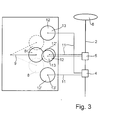
- Fig. 3 is a further embodiment of the adjusting device 3 shown.
- the longitudinal adjustment mechanism 4 for actuating the longitudinal adjustment mechanism 4 here is always in the same direction rotating central drive wheel 8 from the rest position (solid Line) in the first switching position (interrupted drawn Line). In this position is the drive wheel 8 drive coupled to the input side 13, for example the gear 12, the Lticiansverstellmechanismus 4th If the adjustment has taken place, the central drive wheel 8 from the first switching position (dashed or interrupted drawn line) into the resting position (solid line) transferred. To reverse the adjustment, the central Drive wheel 8 in the second switching position (dotted Line) and thereby, for example, with another Gear 12 'on the input side 13 of the Lssensverstellmechanismus 4 drive connected.
- the invention proposes for a motor vehicle steering column unit 1 to provide an adjusting device 3, with which a longitudinal adjustment or a tilt adjustment of a Steering column 2 can be effected and which one between at least two switch positions mechanically adjustable central Drive wheel 8, that of an electric drive unit 7 is driven.
- the central drive wheel 8 is in at least one of its switching positions with the one or with the other adjusting mechanism 4 or 5 drive-coupled.
- the solution according to the invention thus offers the advantage of having only a single drive unit 7 more adjustment mechanisms 4, 5 drive, creating an additional drive unit can be omitted and costs can be saved.
- the adjusting mechanisms 4 and 5 are separate from the adjusting device 3 and arranged via flexible shafts 11 connected with this, so that regardless of the location the adjusting device 3 is arranged on the steering column 2 can be.
- This also offers the possibility of different Series, for example standard version or Full version of the motor vehicle steering column unit 1 to produce and according to a desired extent of the equipment to be produced Install motor vehicle.
Landscapes
- Engineering & Computer Science (AREA)
- Chemical & Material Sciences (AREA)
- Combustion & Propulsion (AREA)
- Transportation (AREA)
- Mechanical Engineering (AREA)
- Steering Controls (AREA)
- Arrangement Or Mounting Of Control Devices For Change-Speed Gearing (AREA)
Applications Claiming Priority (2)
| Application Number | Priority Date | Filing Date | Title |
|---|---|---|---|
| DE10341419A DE10341419A1 (de) | 2003-09-09 | 2003-09-09 | Kraftfahrzeuglenksäuleneinheit |
| DE10341419 | 2003-09-09 |
Publications (2)
| Publication Number | Publication Date |
|---|---|
| EP1514764A2 true EP1514764A2 (fr) | 2005-03-16 |
| EP1514764A3 EP1514764A3 (fr) | 2005-04-13 |
Family
ID=34129699
Family Applications (1)
| Application Number | Title | Priority Date | Filing Date |
|---|---|---|---|
| EP04019876A Withdrawn EP1514764A3 (fr) | 2003-09-09 | 2004-08-21 | Unité de colonne de direction de véhicule automobile |
Country Status (3)
| Country | Link |
|---|---|
| US (1) | US20050092124A1 (fr) |
| EP (1) | EP1514764A3 (fr) |
| DE (1) | DE10341419A1 (fr) |
Cited By (1)
| Publication number | Priority date | Publication date | Assignee | Title |
|---|---|---|---|---|
| JP2011042274A (ja) * | 2009-08-21 | 2011-03-03 | Jtekt Corp | 位置調整式操舵装置 |
Families Citing this family (7)
| Publication number | Priority date | Publication date | Assignee | Title |
|---|---|---|---|---|
| KR100580534B1 (ko) * | 2005-01-03 | 2006-05-15 | 현대자동차주식회사 | 기어를 이용한 틸트·텔레스코픽 모드 변경 타입 모터구동식 조향장치 |
| US8062686B2 (en) * | 2005-04-12 | 2011-11-22 | InovoBiologics, Inc. | Dietary supplement, and methods of use |
| US8056437B2 (en) * | 2005-04-19 | 2011-11-15 | Nexteer (Beijing) Technology Co., Ltd. | Electric steering column lock with single direction actuator travel |
| US7861615B2 (en) * | 2005-04-19 | 2011-01-04 | Gm Global Technology Operations, Inc. | Adjustable steering column assembly |
| US20060230863A1 (en) * | 2005-04-19 | 2006-10-19 | Delphi Technologies, Inc. | Steering column with rake and telescope adjustment |
| DE102007055802A1 (de) * | 2007-12-13 | 2009-06-25 | Zf Lenksysteme Gmbh | Lenksystem in einem Kraftfahrzeug |
| DE102019125796A1 (de) * | 2019-09-25 | 2021-03-25 | Audi Ag | Lenkradanordnung |
Citations (1)
| Publication number | Priority date | Publication date | Assignee | Title |
|---|---|---|---|---|
| DE19641152C2 (de) | 1996-10-07 | 1998-09-17 | Lemfoerder Metallwaren Ag | Kraftfahrzeuglenksäuleneinheit |
Family Cites Families (6)
| Publication number | Priority date | Publication date | Assignee | Title |
|---|---|---|---|---|
| US3396600A (en) * | 1966-10-11 | 1968-08-13 | Gen Motors Corp | Power operated tilt and telescope steering assembly |
| DE3634977A1 (de) * | 1985-10-14 | 1987-04-16 | Fuji Kiko Kk | Anordnung zur neigung eines lenkrades mittels einer hilfsantriebskraft |
| FR2662986B1 (fr) * | 1990-06-07 | 1994-11-18 | Nacam | Dispositif pour le reglage de la position d'une colonne de direction reglable. |
| US5829311A (en) * | 1996-08-15 | 1998-11-03 | Roberson; Jarried E. | Motorized tilt steering device |
| JP2001199350A (ja) * | 2000-01-17 | 2001-07-24 | Toyota Motor Corp | 車両のステアリング装置 |
| US6612198B2 (en) * | 2001-11-01 | 2003-09-02 | Delphi Technologies, Inc. | Lash-free cable drive |
-
2003
- 2003-09-09 DE DE10341419A patent/DE10341419A1/de not_active Withdrawn
-
2004
- 2004-08-21 EP EP04019876A patent/EP1514764A3/fr not_active Withdrawn
- 2004-09-08 US US10/935,740 patent/US20050092124A1/en not_active Abandoned
Patent Citations (1)
| Publication number | Priority date | Publication date | Assignee | Title |
|---|---|---|---|---|
| DE19641152C2 (de) | 1996-10-07 | 1998-09-17 | Lemfoerder Metallwaren Ag | Kraftfahrzeuglenksäuleneinheit |
Cited By (1)
| Publication number | Priority date | Publication date | Assignee | Title |
|---|---|---|---|---|
| JP2011042274A (ja) * | 2009-08-21 | 2011-03-03 | Jtekt Corp | 位置調整式操舵装置 |
Also Published As
| Publication number | Publication date |
|---|---|
| US20050092124A1 (en) | 2005-05-05 |
| EP1514764A3 (fr) | 2005-04-13 |
| DE10341419A1 (de) | 2005-03-31 |
Similar Documents
| Publication | Publication Date | Title |
|---|---|---|
| DE102020129215B4 (de) | Neigungsbügelanordnung für eine lenksäule | |
| EP1425523A1 (fr) | Boite de vitesses a actionneur electromecanique | |
| EP1893456B1 (fr) | Dispositif de verrouillage destine a un arbre de direction presentant une position d'arret selectionnable en cas de mouvement du dispositif de boulon de blocage en direction de la position terminale de liberation | |
| EP1110828A2 (fr) | Dispositif de verrouillage | |
| EP3371003B1 (fr) | Appui-tête avec dispositif de réglage pour réglage de la position d'un appui-tête à entraînement direct | |
| DE102006007600B4 (de) | Drehsteller für elektrische oder elektronische Gräte in einem Kraftfahrzeug | |
| DE102023115292A1 (de) | Aktor zur Bereitstellung eines Drehmoments mit einem Linearantrieb | |
| DE102020122695A1 (de) | Lenkvorrichtung für ein Kraftfahrzeug | |
| DE10254127B4 (de) | Elektromotorischer Möbelantrieb zum Verstellen von Teilen eines Möbels relativ zueinander | |
| DE20213364U1 (de) | Antriebsvorrichtung | |
| DE102008040207A1 (de) | Anordnung zum Wählen und Schalten von Gängen bei einem Schaltgetriebe eines Fahrzeuges | |
| EP1514764A2 (fr) | Unité de colonne de direction de véhicule automobile | |
| DE102005052342B4 (de) | Motorbetriebenes Lenksäulensystem eines Fahrzeuges | |
| WO2000071908A1 (fr) | Bloc-moteur | |
| EP3408144B1 (fr) | Colonne de direction à verrouillage électrique de la direction | |
| DE19906268C2 (de) | Vorrichtung zur elektrischen Verriegelung der Lenkspindel einer Lenkeinrichtung | |
| DE3502341A1 (de) | Steuerung fuer eine kupplung | |
| EP1925772A2 (fr) | Unité de détection | |
| DE10254129B4 (de) | Elektromotorischer Möbelantrieb zum Verstellen von Teilen eines Möbels relativ zueinander | |
| DE102017112522B4 (de) | Schalteinrichtung mit Getriebe zur Schalthebelrückstellung und/oder Schalthebelbeanschlagung und zugehörige Verwendung | |
| DE102009058333A1 (de) | Längseinsteller für einen Fahrzeugsitz | |
| EP1507104B1 (fr) | Mécanisme de commande pour génération d'un mouvement de translation | |
| EP1523633A1 (fr) | Actionneur electromecanique de boite de vitesses | |
| DE9402338U1 (de) | Fahr-Brems-Steuerschalter für elektrisch angetriebene Schienenfahrzeuge | |
| DE102023100304B4 (de) | Aktuatorvorrichtung für eine elektromechanische Lenkungsanordnung |
Legal Events
| Date | Code | Title | Description |
|---|---|---|---|
| PUAI | Public reference made under article 153(3) epc to a published international application that has entered the european phase |
Free format text: ORIGINAL CODE: 0009012 |
|
| PUAL | Search report despatched |
Free format text: ORIGINAL CODE: 0009013 |
|
| AK | Designated contracting states |
Kind code of ref document: A2 Designated state(s): AT BE BG CH CY CZ DE DK EE ES FI FR GB GR HU IE IT LI LU MC NL PL PT RO SE SI SK TR |
|
| AX | Request for extension of the european patent |
Extension state: AL HR LT LV MK |
|
| AK | Designated contracting states |
Kind code of ref document: A3 Designated state(s): AT BE BG CH CY CZ DE DK EE ES FI FR GB GR HU IE IT LI LU MC NL PL PT RO SE SI SK TR |
|
| AX | Request for extension of the european patent |
Extension state: AL HR LT LV MK |
|
| 17P | Request for examination filed |
Effective date: 20050520 |
|
| STAA | Information on the status of an ep patent application or granted ep patent |
Free format text: STATUS: THE APPLICATION HAS BEEN WITHDRAWN |
|
| AKX | Designation fees paid |
Designated state(s): DE FR GB SE |
|
| 18W | Application withdrawn |
Effective date: 20051216 |