EP1514785A1 - Rollerartiges Motorrad - Google Patents
Rollerartiges Motorrad Download PDFInfo
- Publication number
- EP1514785A1 EP1514785A1 EP04021708A EP04021708A EP1514785A1 EP 1514785 A1 EP1514785 A1 EP 1514785A1 EP 04021708 A EP04021708 A EP 04021708A EP 04021708 A EP04021708 A EP 04021708A EP 1514785 A1 EP1514785 A1 EP 1514785A1
- Authority
- EP
- European Patent Office
- Prior art keywords
- air suction
- vehicle
- opening
- suction duct
- vehicle body
- Prior art date
- Legal status (The legal status is an assumption and is not a legal conclusion. Google has not performed a legal analysis and makes no representation as to the accuracy of the status listed.)
- Granted
Links
- 230000005540 biological transmission Effects 0.000 claims abstract description 41
- 238000001816 cooling Methods 0.000 claims abstract description 25
- 239000002828 fuel tank Substances 0.000 claims description 8
- 239000000498 cooling water Substances 0.000 description 6
- XLYOFNOQVPJJNP-UHFFFAOYSA-N water Substances O XLYOFNOQVPJJNP-UHFFFAOYSA-N 0.000 description 6
- XEEYBQQBJWHFJM-UHFFFAOYSA-N Iron Chemical compound [Fe] XEEYBQQBJWHFJM-UHFFFAOYSA-N 0.000 description 4
- 229910000838 Al alloy Inorganic materials 0.000 description 3
- 230000000712 assembly Effects 0.000 description 3
- 238000000429 assembly Methods 0.000 description 3
- 229910045601 alloy Inorganic materials 0.000 description 2
- 239000000956 alloy Substances 0.000 description 2
- 230000000694 effects Effects 0.000 description 2
- 229910052742 iron Inorganic materials 0.000 description 2
- 238000000034 method Methods 0.000 description 2
- 230000000630 rising effect Effects 0.000 description 2
- 238000003466 welding Methods 0.000 description 2
- WTDRDQBEARUVNC-LURJTMIESA-N L-DOPA Chemical compound OC(=O)[C@@H](N)CC1=CC=C(O)C(O)=C1 WTDRDQBEARUVNC-LURJTMIESA-N 0.000 description 1
- 230000002411 adverse Effects 0.000 description 1
- XAGFODPZIPBFFR-UHFFFAOYSA-N aluminium Chemical compound [Al] XAGFODPZIPBFFR-UHFFFAOYSA-N 0.000 description 1
- 229910052782 aluminium Inorganic materials 0.000 description 1
- 238000005266 casting Methods 0.000 description 1
- 239000000110 cooling liquid Substances 0.000 description 1
- 238000013016 damping Methods 0.000 description 1
- 238000004512 die casting Methods 0.000 description 1
- 230000005484 gravity Effects 0.000 description 1
- 239000000463 material Substances 0.000 description 1
- 238000004080 punching Methods 0.000 description 1
- 230000003014 reinforcing effect Effects 0.000 description 1
- 239000007787 solid Substances 0.000 description 1
Images


Classifications
-
- B—PERFORMING OPERATIONS; TRANSPORTING
- B62—LAND VEHICLES FOR TRAVELLING OTHERWISE THAN ON RAILS
- B62K—CYCLES; CYCLE FRAMES; CYCLE STEERING DEVICES; RIDER-OPERATED TERMINAL CONTROLS SPECIALLY ADAPTED FOR CYCLES; CYCLE AXLE SUSPENSIONS; CYCLE SIDE-CARS, FORECARS, OR THE LIKE
- B62K11/00—Motorcycles, engine-assisted cycles or motor scooters with one or two wheels
- B62K11/02—Frames
- B62K11/10—Frames characterised by the engine being over or beside driven rear wheel
-
- B—PERFORMING OPERATIONS; TRANSPORTING
- B62—LAND VEHICLES FOR TRAVELLING OTHERWISE THAN ON RAILS
- B62K—CYCLES; CYCLE FRAMES; CYCLE STEERING DEVICES; RIDER-OPERATED TERMINAL CONTROLS SPECIALLY ADAPTED FOR CYCLES; CYCLE AXLE SUSPENSIONS; CYCLE SIDE-CARS, FORECARS, OR THE LIKE
- B62K2202/00—Motorised scooters
-
- F—MECHANICAL ENGINEERING; LIGHTING; HEATING; WEAPONS; BLASTING
- F16—ENGINEERING ELEMENTS AND UNITS; GENERAL MEASURES FOR PRODUCING AND MAINTAINING EFFECTIVE FUNCTIONING OF MACHINES OR INSTALLATIONS; THERMAL INSULATION IN GENERAL
- F16H—GEARING
- F16H57/00—General details of gearing
- F16H57/04—Features relating to lubrication or cooling or heating
- F16H57/0412—Cooling or heating; Control of temperature
- F16H57/0415—Air cooling or ventilation; Heat exchangers; Thermal insulations
- F16H57/0416—Air cooling or ventilation
-
- F—MECHANICAL ENGINEERING; LIGHTING; HEATING; WEAPONS; BLASTING
- F16—ENGINEERING ELEMENTS AND UNITS; GENERAL MEASURES FOR PRODUCING AND MAINTAINING EFFECTIVE FUNCTIONING OF MACHINES OR INSTALLATIONS; THERMAL INSULATION IN GENERAL
- F16H—GEARING
- F16H57/00—General details of gearing
- F16H57/04—Features relating to lubrication or cooling or heating
- F16H57/048—Type of gearings to be lubricated, cooled or heated
- F16H57/0487—Friction gearings
- F16H57/0489—Friction gearings with endless flexible members, e.g. belt CVTs
Definitions
- This invention relates to a vehicle, in particular a scooter type motorcycle, having a unit swing type power unit supported for swinging on a vehicle body frame, wherein an introduction opening for drawing in cooling air is formed at a transmission chamber of the unit swing type power unit, and wherein an air suction duct for introducing the cooling air to the introduction opening is fixedly supported on the vehicle body frame.
- a scooter type of motorcycle comprises a vehicle body frame which supports a unit swing type power unit for free swinging.
- the unit swing type power unit is made by combining together an engine and a transmission unit into a single unit to drive a rear wheel supported with a shaft of the power unit and to propel the vehicle.
- As the transmission preferably a V-belt type automatic transmission is used.
- the V-belt type automatic transmission is housed in a transmission chamber so that less noise leaks outside.
- a connecting part of the air suction duct is made of a bellows.
- the connecting part of the bellows of the air suction duct has a relatively small opening area of the inside passage for the suctioned air relative to its external shape, which leads to problems such as lowering in cooling efficiency.
- an object of the invention to provide an improved vehicle, in particular a scooter type motorcycle having an increased cooling efficiency.
- the air suction duct comprises a connection opening which covers the introduction opening for a freely swinging movement therebetween.
- connection opening surrounds the introduction opening with a clearance being provided therebetween.
- the introduction opening is provided at a front side of the transmission chamber and/or in that the connection opening is provided at a rear end of a main body of the air suction duct.
- a fresh air suction opening is provided at a front end portion of a main body of the air suction duct.
- a fresh air suction opening is open to an interior of the vehicle body, in particular to center tunnel provided laterally between footrest regions of the vehicle.
- the fresh air suction opening of the air suction duct is located above a fuel tank.
- the vehicle body frame comprises an upper frame extending from a head pipe through a footrest region and below a seat to the rear end of the vehicle body, and a lower frame extending from a middle portion of the upper frame downwardly, and wherein the air suction duct is located between and attached to the upper and/or lower frames.
- a cooling fan is provided in the transmission chamber, in particular on an outer side of a drive pulley of a continuously variable transmission, for drawing in the cooling air into the transmission chamber.
- a discharge opening is formed on a rear side of the transmission chamber, the discharge opening preferably being directed toward a rear wheel of the vehicle.
- a main body of the air suction duct comprises an attachment hole for attachment of the air suction duct to a lower frame of the vehicle body frame and/or in that a connection opening is provided at a rear upper part of the main body of the air suction duct for attachment thereof to an upper frame of the vehicle body frame, in particular to a step part of a footrest thereof.
- FIG. 1 is a side view of a scooter type motorcycle as a preferred example of a vehicle according to the invention.
- reference numeral 1 denotes a scooter type motorcycle of this embodiment.
- the scooter type motorcycle 1 comprises a vehicle body frame 4 with its head pipe 21 having a front fork 7 that can be turned.
- a front wheel 6 is supported at the lower part of the front fork 7.
- Steering handlebars 8 are attached to the upper part of the front fork 7.
- the vehicle body frame 4 is made up of: an upper frame 23 extending from the head pipe 21 through a footrest region 22 and below a seat 9 to the rear end of the vehicle body, and a lower frame 24 extending from the middle of the upper frame 23 downward.
- the upper frame 23 is made of aluminum alloy while the lower frame 24 is made of iron-based alloy.
- the vehicle body frame 4 is made to be light-weight by making part of it using aluminum alloy that is relatively light.
- the upper frame 23 is made up of separate parts: a front half 25 extending from the head pipe 21 to the footrest region 22, and a rear half 26 welded to the rear end of the front half 25 and extending to the rear end of the vehicle body.
- the front half 25 is made up of: the head pipe 21, paired right and left down frames 27 extending from the head pipe 21 rear downward, and two cross members 28, 29 interposed between those down frames 27, with these parts formed into an integral body by the so-called gravity casting process.
- the rear half 26 of the upper frame 23 is made up of: a left hand longitudinal extension part 31 and a right hand longitudinal extension part 32 both extending longitudinally at the left and right hand lateral ends of the vehicle width, and first to three cross members 33 to 35 interconnecting the front end, middle, and rear end portions of the longitudinal extension parts 31 and 32, with these parts formed into an integral body by the vacuum die casting process.
- the front part of the unit swing type power unit 3 is connected for free up and down swinging through supporting links 5 (to be described later) at longitudinally central portions of the left and right hand longitudinal extension parts 31, 32.
- a damper unit bracket 36 for connection to the upper end of a damper unit 15 is provided at the rear end of the longitudinal extension part 31 on the left hand side of the vehicle body.
- the front end of each of the left and right hand longitudinal extension parts 31 and 32 is provided with a bracket 37 projecting downward for connecting to the middle part of the lower frame 24 (to be described later).
- the first cross member 33 for interconnecting the front end portions and the second cross member 34 for interconnecting the middle portions of the left and right hand longitudinal extension parts 31 and 32 are formed so that a large-sized holding box 85 capable of storing a crash helmet can be provided between those cross members.
- the holding box 85 is of a similar constitution to that employed in the conventional scooter type of motorcycle, with its top opening covered and uncovered with the seat 9.
- the seat 9 is made up of a rider's seat portion 9a and a co-rider's seat portion 9b.
- the holding box 85 is made up of a front helmet holding portion 85a and a rear helmet holding portion 85b, with the former located below the rider's seat portion 9a while the latter below the co-rider's seat portion 9b.
- the front helmet holding portion 85a is open while the rear helmet holding portion 85b is covered with a box cover 85c.
- the rider's seat portion 9a serves as a lid on the front helmet holding portion 85a, and can be swung up and down about a pivot point on its front end to cover and uncover.
- the co-rider's seat portion 9b is placed on the box cover 85c of the rear helmet holding portion 85b.
- the rider's seat portion 9a is swung up forward about its front end pivot to store a crash helmet in the front helmet holding portion 85a and the rear helmet holding portion 85b.
- the box cover 85c is provided with plural holes 85c1 in the lateral center as shown in FIGs 3 and 4.
- the holding box 85 is placed above and relatively close to the unit swing type of power unit 3 and affected by heat which accumulates in the holding box 85.
- the accumulated heat can be let out through the holes 85c1.
- the driver's seat portion 9a When the driver's seat portion 9a is to be closed down, it would be less easy to do so if no passage were present for letting out air in the holding box 85. However, since air is let out through the holes 85c1, the driver's seat portion 9a can be closed down smoothly.
- the plural holes 85c1 provided in the box cover 85c as shown in FIGs. 3 and 4 are located in the lateral center of the box cover 85c and that they are covered with the co-rider's seat portion 9b, water is prevented from finding its way through the holes 85c1 into the holding box 85.
- the down frames 27 of the front half 25 connected to the front ends of the longitudinal extension parts 31 and 32 extend rear downward. Since the front ends of the longitudinal extension parts 31 and 32 are supported firmly with the down frames 27 in the vertical direction, it is possible to constitute the upper frame 23 of a high torsional rigidity by combining the front half 25 with the rear half 26.
- the longitudinal extension parts 31 and 32 are made to have a high rigidity even by themselves by integrally forming X-shaped reinforcing ribs as seen in side view on the inner sides of the front portions of the longitudinal extension parts 31 and 32 each having a cross section of a squared U-shape lying on its one side.
- the lower frame 24 of the vehicle body frame 4 is made up of: paired left and right hand pipes 81, 82 extending longitudinally below the upper frame 23, and first to fourth cross members 83 to 86 laterally interconnecting these pipes 81, 82.
- Both of the pipes 81, 82 are formed as shown in FIG. 1 in the shape of a horizontal bar with its both end portions bent up to form obtuse angles, with their front ends each secured with a fitting bolt 87 to the front half 25 of the upper frame 23 while their rear ends each secured to the rear half 26 of the upper frame 23 through a connecting bracket 88.
- Each connecting bracket 88 is made of iron-based alloy like the pipes 81, 82 in a box shape with its lower end welded to the pipe 81 or 82 while its upper end secured with fitting bolts 89 to the rear half 26.
- both pipes 81, 82 are each provided with a connecting plate 90 to rise up at the front end of its lower, longitudinally extending portion.
- the front end portion of the rear half 26 is provided with brackets 37 to extend downward.
- the brackets 90 and the brackets 37 are tightened together with fitting bolts 91 as shown in FIG. 1, so that the lower frame 24 is supported with the upper frame 23.
- These left and right hand pipes 81, 82 are each provided, by welding, with a stay 92 for supporting the lower portion of a vehicle body cover 10 and with a stay 95 for supporting a side stand.
- These pipes 81, 82 support a radiator 96 through a bracket 110.
- the radiator 96 is of a conventionally well-known, lateral water flow type placed as shown in FIG. 1 to rise up forward to be located below the front end portions of the pipes 81, 82 extending rear downward. Part of cooling water passages between the radiator 96 and an engine 11 is formed with the pipes 81, 82.
- the radiator 96 and the pipes 81, 82 are interconnected through cooling water hoses 97 while the pipes 81, 82 and the engine 11 are interconnected through cooling water hoses 98. Accordingly, at least a portion of a cooling water system of the vehicle is formed by at least a portion of the body frame of the vehicle.
- the cooling water system of a vehicle comprises a frame element of the body frame of the vehicle, preferably the frame element extends in a longitudinal direction of the vehicle, more preferably the frame element is a tube-like element.
- An internal cross-section of the frame element may be of any suitable shape, in particular round or rectangular.
- the frame element which, in particular, extends in parallel to another frame element such as a main frame element of the vehicle frame.
- the frame element which is part of the cooling water system for an engine of the vehicle is preferably arranged between the engine and a cooling device such as a radiator and is configured to transport a cooling liquid from the engine towards the radiator and/or vice versa. It is also possible that a plurality of such frame elements are provided.
- the frame elements may be interconnected to one another and/or to the radiator and/or to the engine via further solid tubes or flexible hoses which are not part of the body frame of the vehicle.
- the frame element in the present embodiment, being a pipe 81 or a pipe 82 structurally increases the stability of the body frame of the vehicle and is preferably connected to another part of the body frame via connecting elements such as bolts or a welding portion.
- the frame element may be connected to another part of the body frame at a front end only and/or at a rear end only and/or at multiple positions along its longitudinal direction including a front end or a rear end.
- the cross member 85 interconnecting both pipes 81, 82 is made to support a fuel tank 99.
- the fuel tank 99 is placed in a space formed above the cross member 85, between the cross member 85 and the holding box 85.
- the cross member 86 is formed to be convex downward as seen from behind and its lateral center is provided with a bracket 100 for the main stand.
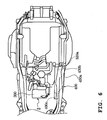
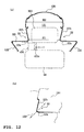
- the footrest regions 22 are each made up of a step portion 22a extending generally horizontally and a (vertical) wall portion 22b rising from the inside end of the step portion 22a.
- the paired left and right vertical wall portions 22b are tilted so that they are slightly more distant from each other as they extend upward.
- An upper cover 120 is placed over the (vertical) wall portions 22b to form a center tunnel 121.
- the center tunnel 121 is formed with an upper width H2 wider than a lower width H 1.
- a side cover 122 is connected to the lower part of each step portion 22a.
- the front portion of the holding box 85 is placed in the center tunnel 121.
- the fuel tank 99 is placed below the center tunnel 121.
- the center tunnel 121 with the wider upper width H2 and the narrower lower width H1 as described above makes it possible to place effectively in the center tunnel 121 the holding box 85 even if its front upper portion has a large volume. It is also possible to improve foot landing comfort and esthetic appearance by keeping a narrow vehicle width while securing a foot placement space H3. It is further possible to improve gripping main body when the wide width portion of the upper portion of the center tunnel 121 is squeezed by legs. As shown in FIG. 12(b), the footrest region 22 is divided into the left and right portions and each has the (vertical) wall portion 22b rising up from the inside end of the step portion 22a.
- the shape in which the (vertical) wall portion 22b slightly tilted to widen up outward can be formed easily by drawing paired press dies 123, 124 in the direction of the bisector of the angle between the step portion 22a and the vertical wall portion 22b.
- a footrest 130 is tightly attached to the upper frame 23 of the vehicle body frame 4 using fitting bolts 131 to 134 in four positions.
- the footrest 130 is tightly attached to a front side of the part where the unit swing type power unit 3 is to be mounted.
- the tight attachment of the footrest 130 increases rigidity of the area around part of the upper frame 23 where the unit swing type power unit 3 is mounted.
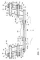
- the unit swing type power unit 3 having a rear wheel 2 is supported on the rear part of the vehicle body frame 4 through links 5 so as to swing up and down freely. As shown in FIGs. 5, 7, and 8, the unit swing type of power unit 3 is elastically supported through rubber dampers 53, 54 with cylindrical bosses 51, 52 provided two for each in positions near the inner sides of the left and right hand longitudinal extension parts 31, 32.
- Each link 5 is made up of side plates 58, 59 formed in a plate shape by a punching process and bosses 55 to 57 made of drawn material and welded to three positions on the side plates 58, 59, two at their longitudinal ends and one in the center.
- the topmost-located boss 55 serves as a swing base S1 of the link 5
- the lower end boss 57 serves as a swinging part S2
- the boss 56 in the middle serves as a middle supporting part S3.
- An attachment plate 200 projecting toward the inside of the vehicle body is welded to the side plate 58 of each of the left and right links 5.
- An engine bracket 201 is secured between the left and right attachment plates 200 using fitting bolts 202, 205.
- a boss 203 welded to the engine bracket 201 serves as a swinging end.
- the attachment plate 200 is welded to the lower end boss 57 welded to the right hand link 5, thereby increasing the supporting strength of the boss 57.
- the cylindrical bosses 51, 52 are each formed on the rear half 26 of the vehicle body frame 4 in upper and lower positions on an extension 26a extending vertically by the side of the link 5 with the upper boss 51 located more forward than the lower boss 52. As a result, the link 5 is tilted to extend down rearward.
- the topmost boss 55 serving as a swinging base and the middle boss 56 are respectively provided with frame connection support shafts 61, 62 projecting toward the outer side of the vehicle body.
- a support shaft 63 for power unit connection is passed through the lowermost boss 57 serving as the swinging end and through the boss 203 of the engine bracket 201.
- the frame connection support shafts 61, 62 are bolts passing through the bosses 55, 56 of the link 5 and through the cylindrical bosses 51, 52 of the vehicle body frame 4, with their heads projecting in the side directions.
- the central portions of the rubber damper assemblies 64, 65 provided inside the cylindrical bosses 51, 52 are tightened to the link 5.
- the rubber damper assemblies 64, 65 are made up of: inner cylinders 66, 67 tightened to the link 5 using support shafts 61, 62 inserted therein, outer cylinders 68, 69 press fit to the inside round surfaces of the cylindrical bosses 51, 52, and rubber dampers 53, 54 interposed between the inner cylinders 66, 67 and the outer cylinders 68, 69.
- Rubber dampers 53, 54 are glued to the outside round surfaces of the inner cylinders 66, 67 and inside round surfaces of the outer cylinders 68, 69 in the state of being solidified and filling the spaces between the inner cylinders 66, 67 and outer cylinders 68, 69.
- the links 5 are elastically supported on the vehicle body frame 4 through the rubber dampers 53, 54 located laterally outer than the links 5, as the rubber damper assemblies 64, 65 are press fit into the cylindrical bosses 51, 52 and tightened to the links 5 using the support shafts 61, 62.
- the support shaft 63 for power unit connection provided at the swinging end of the links 5 is a bolt.
- the boss 203 is located between the bosses 57.
- the support shaft 63 extends from the right hand link 5 to the left hand link 5, passes through the bosses 57 and the boss 203.
- the right hand link 5 and the left hand link 5 are interconnected through the engine bracket 201 and through the power unit connecting support shaft 63 to form a link assembly 74.
- Attachment of the engine bracket 201 is made as follows: First the engine bracket 201 is temporarily stopped between the attachment plates 200 of the right and left hand links 5 using fitting bolts 202, 205. In the state of the engine bracket 201 being stopped temporarily, brackets 75 for connecting the unit swing type of power unit 3 are placed between the bosses 57 of the right and left links 5 and the boss 203 of the engine bracket 201, the support shaft 63 for connecting the power unit is passed from right through the boss 57, the connection bracket 75, the boss 203, the boss 57, a nut 150 is screwed to the projecting end of the support shaft 63 from the left boss 57, and the fitting bolts 202, 205 that were temporarily stopped are tightened.
- the unit swing type of power unit 3 is assembled and supported with good accuracy using the support shaft 63 for connecting the power unit without being affected by tolerances.
- Sleeves 76 connected to the brackets 75 for connecting the unit swing type of power unit 3 are made to be rotatable through sliding bearings 77.
- the unit swing type of power unit 3 swings up and down relative to the links 5 and the vehicle body frame 4 as the sleeves 76 rotate.
- This embodiment is constituted to support the unit swing type of power unit 3 at three points: at the bosses 55 of the left and right links 5, and the boss 203 of the engine bracket 201 interconnecting the left and right links 5.
- This constitution improves driving stability by restricting bend of the support shaft 63 for connecting the power unit and also improves sliding main body of the unit swing type power unit 3 as it swings up and down.
- the vehicle being straddle-type vehicle, in particular a motorcycle such as a scooter-type motorcycle, comprises a rear driving unit which is swingably interconnected to a main body frame of the vehicle.
- a connecting arrangement between the rear drive unit and the body frame comprises a swinging axis being preferably arranged at a front end of the rear drive unit.
- a rear portion of the rear drive unit is supported on the body frame by a combined spring-damping unit such as rear cushion 15.
- the connecting arrangement comprises a number of, preferably three, parallel shafts being firmly interconnected to have a fixed position relative to one another.
- the shafts are symmetrically arranged on both sides of a virtual vertical plane which divides the vehicle in a left and a right half in its longitudinal direction. At least two of the shafts which are preferably arranged vertically to said plane are connected to a body frame member such as an extension part 31, 32 of the body frame of the vehicle, preferably with a flexible member such as a rubber damper interposed between the shafts and the frame member.
- the third shaft is configured to function as a rotating axis for a connecting portion of the rear drive unit, being a unit swing type power unit 3 in the embodiment shown in Figs. 1 and 7.
- the third shaft which itself is not directly connected to the frame member penetrates said virtual plane from one side to the other.
- the third shaft is preferably fixedly connected with reference to its position to the two other shafts via link members 5 which are arranged diagonally with respect to the shafts and/or to that virtual plane.
- the shafts are formed as bolts 61, 62, 63 being held in bosses 55, 56, 57, the bosses connected via links 5, the links being diagonally arranged with respect to the bosses and the bolts, the bolts being held in rubber portions 53, 54 which are themselves supported in holes provided in the body frame members 31, 32. If seen in a lateral view, as shown in Fig. 1, the shafts are arranged diagonally with respect to a second virtual vertical plane being arranged vertically to the first virtual vertical plane.
- the first shaft being the uppermost of the three shafts is also the foremost of the three shafts
- the third shaft which penetrates the first virtual vertical plane is the lowermost and the rearmost of the three shafts.
- the rear drive unit being the unit swing type power unit 3
- the rear drive unit is centrally supported by at least one holding member arrange at said third shaft.
- the unit swing type power unit 3 is a single body made up of an engine main body 300 and a continuously variable transmission (CVT) 301 of a V-belt type.
- the engine main body 300 is made up of: a crankcase 307 made of aluminum alloy, a cylinder block 302 with cylinders directed generally horizontally forward and fit to the front face of the crankcase 307, a cylinder head 303 mated to the cylinder block 302 and tightened, and a head cover 304 removably mated to the front face of the cylinder head 303.
- Pistons 305 inserted to be slidable in the cylinder block 302 are connected through connecting rods 306 to a crankshaft 308 placed in the crankcase 307 and directed in the direction of vehicle width.
- the V-belt type CVT 301 is made by housing a transmission main body in a transmission chamber 320 of the transmission case 310 extending from the left side of the engine main body 300 rearward along the left hand side of the vehicle.
- the transmission main body is constituted by routing a V-belt 313 around a drive pulley 311 and a driven pulley 312, with the former attached to the left end of the crankshaft (drive shaft) 308 located on the side of the engine main body 300 in the transmission case 310 and with the latter attached to the driven shaft 314 located on the side of the rear wheel 2.
- Rotation of the driven shaft 314 is transmitted, while being reduced according to the ratio of cogs of gears, to the rear wheel shaft 316 through an intermediate shaft 315 placed in the transmission chamber 320.
- the transmission case 310 is made up of: a case main body 317 formed integrally with the crankcase 307 and extending to the rear wheel shaft 316, an aluminum alloy-made case cover 318 removably attached to the outer (left) side of the case main body 317 and a resin-made cover 319 placed over the external surface of the case cover 318.
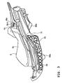
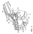
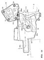
- an air suction duct 400 is provided to suction cooling air into the transmission chamber 320 of the unit swing type of power unit 3.
- the unit swing type of power unit 3 is adapted that the front part of the transmission case 310 is made to project to form an introduction opening 320a on the front side of the transmission chamber 320. Cooling air is drawn by the rotation of a cooling fan 330 provided on the outer side of the drive pulley 311 through the introduction opening 320a, flows and cools the transmission chamber 320 and goes out through a discharge opening 320b formed on the rear side of the transmission case 310.
- the air suction duct 400 is made up of a duct main body 400a with its rear side having a connection opening 400b and with its front side having a fresh air suction opening 400c.
- the rear upper part 400a1 of the duct main body 400a is secured to the step part 130a of the footrest 130 using two bolts 410 and attached through the footrest 130 to the upper frame 23.
- An attachment hole 400a2 is bored through the central part of the duct main body 400a to attach it to a bracket 420 of the lower frame 24 by inserting a fitting bolt 411 from outside through the attachment hole 400a2.
- the air suction duct 400 is supported simply and securely on the vehicle body frame 4 by attaching the air suction duct 400 to the upper frame 23 and to the lower frame 24.
- a clearance 800 is present between the connection opening 400b of the air suction duct 400 and the introduction opening 320a.
- the connection opening 400b covers the introduction opening 320a so that the introduction opening 320a can swing with the unit swing type of power unit 3.
- the fresh air suction opening 400c of the air suction duct 400 extends forward from the duct main body 400a and is open to the interior of the vehicle body. Fresh air is drawn through the fresh air suction opening 400c to the duct main body 400a, through the connection opening 400b and, before exiting through the discharge opening 320b, sent to the transmission chamber 320.
- connection opening 400b of the air suction duct 400 covers the introduction opening 320a so that it can swing, opening area of the air suction passage for drawing cooling air into the transmission chamber 320 of the unit swing type of power unit 3 that swings can be easily secured to improve cooling efficiency.
- the fresh air suction opening 400c of the air suction duct 400 is open to the interior of the vehicle body, mud and water are prevented from entering the vehicle body from outside when the vehicle runs.
- the fresh air suction opening 400c of the air suction duct 400 is located above the fuel tank 99, mud and water are prevented from entering from under the vehicle body by the presence of the fuel tank 99 when the vehicle runs.
- This invention is applicable to a vehicle, such as preferably a scooter type motorcycle, provided with an air suction duct for drawing cooling air into the transmission chamber of a unit swing type of power unit.
- a scooter type of motorcycle has a unit swing type of power unit 3 supported for free swinging on the vehicle body frame 4, with the unit swing type of power unit 3 having an air suction duct 400 for drawing cooling air into the transmission chamber 320 of the unit swing type of power unit 3.
- An introduction opening 320a is formed on the front side of the transmission chamber 320.
- the air suction duct 400 is supported on the vehicle body frame 4.
- the air suction duct 400 has: a connection opening 400b covering the introduction opening 320a so that it can swing, and a fresh air suction opening 400c that is open to the interior of the vehicle body.
- this invention provides amongst others the following effects.
- the air suction duct has the connection opening that covers the introduction opening so that the introduction opening can swing, it is possible to easily secure the opening area of the air suction passage for introducing cooling air into the transmission chamber of the unit swing type of power unit that swings, and to improve cooling efficiency. Moreover, since the air suction duct has the fresh air suction opening that is open to the interior of the vehicle body, it is possible to prevent mud and water from entering from outside the vehicle body while the vehicle is running.
- the fresh air suction opening is located above the fuel tank, it is possible to prevent mud and water from entering the fresh air suction opening from under the vehicle body when the vehicle is running.
- the air suction duct is attached to the upper and lower frames, the air suction duct is supported securely in a simple manner on the vehicle body frame.
Landscapes
- Engineering & Computer Science (AREA)
- Mechanical Engineering (AREA)
- Automatic Cycles, And Cycles In General (AREA)
- Axle Suspensions And Sidecars For Cycles (AREA)
Applications Claiming Priority (2)
| Application Number | Priority Date | Filing Date | Title |
|---|---|---|---|
| JP2003322330A JP4379864B2 (ja) | 2003-09-12 | 2003-09-12 | スクータ型自動二輪車 |
| JP2003322330 | 2003-09-12 |
Publications (2)
| Publication Number | Publication Date |
|---|---|
| EP1514785A1 true EP1514785A1 (de) | 2005-03-16 |
| EP1514785B1 EP1514785B1 (de) | 2006-11-15 |
Family
ID=34132073
Family Applications (1)
| Application Number | Title | Priority Date | Filing Date |
|---|---|---|---|
| EP20040021708 Expired - Lifetime EP1514785B1 (de) | 2003-09-12 | 2004-09-13 | Rollerartiges Motorrad |
Country Status (6)
| Country | Link |
|---|---|
| EP (1) | EP1514785B1 (de) |
| JP (1) | JP4379864B2 (de) |
| CN (1) | CN1330528C (de) |
| DE (1) | DE602004003189T2 (de) |
| ES (1) | ES2275160T3 (de) |
| TW (1) | TWI247704B (de) |
Cited By (2)
| Publication number | Priority date | Publication date | Assignee | Title |
|---|---|---|---|---|
| EP1688343A1 (de) * | 2005-02-02 | 2006-08-09 | Yamaha Hatsudoki Kabushiki Kaisha | Im Grätschsitz zu benutzendes Fahrzeug |
| EP3032143A1 (de) * | 2014-12-09 | 2016-06-15 | Kwang Yang Motor Co., Ltd. | Verteilergetriebe und motorrad damit |
Families Citing this family (3)
| Publication number | Priority date | Publication date | Assignee | Title |
|---|---|---|---|---|
| CN100406339C (zh) * | 2003-05-20 | 2008-07-30 | 雅马哈发动机株式会社 | 具有引擎进气构造的机动二轮车 |
| JP2009161014A (ja) * | 2007-12-28 | 2009-07-23 | Yamaha Motor Co Ltd | 鞍乗型車両 |
| CN103387025B (zh) * | 2012-05-07 | 2017-06-16 | 光阳工业股份有限公司 | 具有散热导风效果的摩托车 |
Citations (2)
| Publication number | Priority date | Publication date | Assignee | Title |
|---|---|---|---|---|
| JPH0565086A (ja) * | 1991-09-06 | 1993-03-19 | Suzuki Motor Corp | スクータのエンジン冷却装置 |
| EP0953501A2 (de) * | 1998-04-27 | 1999-11-03 | Yamaha Hatsudoki Kabushiki Kaisha | Motorkühlungsstruktur für motorrollerartiges Fahrzeug |
Family Cites Families (1)
| Publication number | Priority date | Publication date | Assignee | Title |
|---|---|---|---|---|
| JP3978335B2 (ja) * | 2001-12-20 | 2007-09-19 | ヤマハ発動機株式会社 | スクータ型自動二輪車の新気取入構造 |
-
2003
- 2003-09-12 JP JP2003322330A patent/JP4379864B2/ja not_active Expired - Fee Related
-
2004
- 2004-08-31 TW TW93126273A patent/TWI247704B/zh not_active IP Right Cessation
- 2004-09-10 CN CNB2004100791413A patent/CN1330528C/zh not_active Expired - Lifetime
- 2004-09-13 EP EP20040021708 patent/EP1514785B1/de not_active Expired - Lifetime
- 2004-09-13 DE DE200460003189 patent/DE602004003189T2/de not_active Expired - Lifetime
- 2004-09-13 ES ES04021708T patent/ES2275160T3/es not_active Expired - Lifetime
Patent Citations (2)
| Publication number | Priority date | Publication date | Assignee | Title |
|---|---|---|---|---|
| JPH0565086A (ja) * | 1991-09-06 | 1993-03-19 | Suzuki Motor Corp | スクータのエンジン冷却装置 |
| EP0953501A2 (de) * | 1998-04-27 | 1999-11-03 | Yamaha Hatsudoki Kabushiki Kaisha | Motorkühlungsstruktur für motorrollerartiges Fahrzeug |
Non-Patent Citations (1)
| Title |
|---|
| PATENT ABSTRACTS OF JAPAN vol. 0173, no. 77 (M - 1446) 15 July 1993 (1993-07-15) * |
Cited By (3)
| Publication number | Priority date | Publication date | Assignee | Title |
|---|---|---|---|---|
| EP1688343A1 (de) * | 2005-02-02 | 2006-08-09 | Yamaha Hatsudoki Kabushiki Kaisha | Im Grätschsitz zu benutzendes Fahrzeug |
| US7478697B2 (en) | 2005-02-02 | 2009-01-20 | Yamaha Hatsudoki Kabushiki Kaisha | Straddle type vehicle |
| EP3032143A1 (de) * | 2014-12-09 | 2016-06-15 | Kwang Yang Motor Co., Ltd. | Verteilergetriebe und motorrad damit |
Also Published As
| Publication number | Publication date |
|---|---|
| JP4379864B2 (ja) | 2009-12-09 |
| EP1514785B1 (de) | 2006-11-15 |
| DE602004003189T2 (de) | 2007-09-27 |
| JP2005088661A (ja) | 2005-04-07 |
| DE602004003189D1 (de) | 2006-12-28 |
| TW200512122A (en) | 2005-04-01 |
| CN1597432A (zh) | 2005-03-23 |
| TWI247704B (en) | 2006-01-21 |
| ES2275160T3 (es) | 2007-06-01 |
| CN1330528C (zh) | 2007-08-08 |
Similar Documents
| Publication | Publication Date | Title |
|---|---|---|
| US7270210B2 (en) | Body frame for motorcycle | |
| US7849947B2 (en) | Motorcycle frame structure | |
| US7845451B2 (en) | Motorcycle frame structure | |
| AU2007221901B2 (en) | Saddle ride type vehicle | |
| US20030111283A1 (en) | Frame assembly for scooter-type vehicle | |
| EP0960808A2 (de) | Antriebssystem für Motorräder | |
| EP1304283A1 (de) | Rollerartiges Motorrad | |
| JP3862345B2 (ja) | 2サイクルエンジンのポンプ駆動構造 | |
| EP1514785B1 (de) | Rollerartiges Motorrad | |
| EP0952076B1 (de) | Rollerartiges Fahrzeug | |
| US6397964B1 (en) | Scooter type vehicle | |
| EP0952075B1 (de) | Rollerartiges Fahrzeug | |
| EP0952074B1 (de) | Rollerartiges Fahrzeug | |
| JPH0329966B2 (de) | ||
| CN1935585B (zh) | 低底板型摩托车 | |
| JP2005280508A (ja) | 自動二輪車のドライサンプ式潤滑装置 | |
| JP2005088659A (ja) | 自動二輪車 | |
| US7398755B1 (en) | Mounting plate for internal combustion engine | |
| JP4458991B2 (ja) | スクータ型自動二輪車 | |
| JP4530787B2 (ja) | 自動二輪車 | |
| CN100436242C (zh) | 低底式车辆 | |
| JP4664328B2 (ja) | スクータ型自動二輪車 | |
| JP4070047B2 (ja) | スクータ型車両の足載せ構造 | |
| JPH11301564A (ja) | 自動二輪車の後輪支持構造 | |
| CN1331707C (zh) | 两轮摩托车 |
Legal Events
| Date | Code | Title | Description |
|---|---|---|---|
| PUAI | Public reference made under article 153(3) epc to a published international application that has entered the european phase |
Free format text: ORIGINAL CODE: 0009012 |
|
| AK | Designated contracting states |
Kind code of ref document: A1 Designated state(s): AT BE BG CH CY CZ DE DK EE ES FI FR GB GR HU IE IT LI LU MC NL PL PT RO SE SI SK TR |
|
| AX | Request for extension of the european patent |
Extension state: AL HR LT LV MK |
|
| 17P | Request for examination filed |
Effective date: 20050120 |
|
| 17Q | First examination report despatched |
Effective date: 20050519 |
|
| AKX | Designation fees paid |
Designated state(s): DE ES FR GB IT |
|
| GRAP | Despatch of communication of intention to grant a patent |
Free format text: ORIGINAL CODE: EPIDOSNIGR1 |
|
| GRAS | Grant fee paid |
Free format text: ORIGINAL CODE: EPIDOSNIGR3 |
|
| GRAA | (expected) grant |
Free format text: ORIGINAL CODE: 0009210 |
|
| AK | Designated contracting states |
Kind code of ref document: B1 Designated state(s): DE ES FR GB IT |
|
| REG | Reference to a national code |
Ref country code: GB Ref legal event code: FG4D |
|
| REF | Corresponds to: |
Ref document number: 602004003189 Country of ref document: DE Date of ref document: 20061228 Kind code of ref document: P |
|
| ET | Fr: translation filed | ||
| REG | Reference to a national code |
Ref country code: ES Ref legal event code: FG2A Ref document number: 2275160 Country of ref document: ES Kind code of ref document: T3 |
|
| PLBE | No opposition filed within time limit |
Free format text: ORIGINAL CODE: 0009261 |
|
| STAA | Information on the status of an ep patent application or granted ep patent |
Free format text: STATUS: NO OPPOSITION FILED WITHIN TIME LIMIT |
|
| 26N | No opposition filed |
Effective date: 20070817 |
|
| REG | Reference to a national code |
Ref country code: FR Ref legal event code: PLFP Year of fee payment: 13 |
|
| REG | Reference to a national code |
Ref country code: FR Ref legal event code: PLFP Year of fee payment: 14 |
|
| REG | Reference to a national code |
Ref country code: FR Ref legal event code: PLFP Year of fee payment: 15 |
|
| PGFP | Annual fee paid to national office [announced via postgrant information from national office to epo] |
Ref country code: GB Payment date: 20200922 Year of fee payment: 17 |
|
| PGFP | Annual fee paid to national office [announced via postgrant information from national office to epo] |
Ref country code: ES Payment date: 20201120 Year of fee payment: 17 |
|
| GBPC | Gb: european patent ceased through non-payment of renewal fee |
Effective date: 20210913 |
|
| PG25 | Lapsed in a contracting state [announced via postgrant information from national office to epo] |
Ref country code: GB Free format text: LAPSE BECAUSE OF NON-PAYMENT OF DUE FEES Effective date: 20210913 |
|
| REG | Reference to a national code |
Ref country code: ES Ref legal event code: FD2A Effective date: 20221027 |
|
| PG25 | Lapsed in a contracting state [announced via postgrant information from national office to epo] |
Ref country code: ES Free format text: LAPSE BECAUSE OF NON-PAYMENT OF DUE FEES Effective date: 20210914 |
|
| P01 | Opt-out of the competence of the unified patent court (upc) registered |
Effective date: 20230527 |
|
| PGFP | Annual fee paid to national office [announced via postgrant information from national office to epo] |
Ref country code: FR Payment date: 20230927 Year of fee payment: 20 Ref country code: DE Payment date: 20230920 Year of fee payment: 20 |
|
| PGFP | Annual fee paid to national office [announced via postgrant information from national office to epo] |
Ref country code: IT Payment date: 20230927 Year of fee payment: 20 |
|
| REG | Reference to a national code |
Ref country code: DE Ref legal event code: R071 Ref document number: 602004003189 Country of ref document: DE |