EP1514794A2 - Coque de bateau - Google Patents
Coque de bateau Download PDFInfo
- Publication number
- EP1514794A2 EP1514794A2 EP04021186A EP04021186A EP1514794A2 EP 1514794 A2 EP1514794 A2 EP 1514794A2 EP 04021186 A EP04021186 A EP 04021186A EP 04021186 A EP04021186 A EP 04021186A EP 1514794 A2 EP1514794 A2 EP 1514794A2
- Authority
- EP
- European Patent Office
- Prior art keywords
- hull
- tubular members
- hull according
- tubular member
- boat
- Prior art date
- Legal status (The legal status is an assumption and is not a legal conclusion. Google has not performed a legal analysis and makes no representation as to the accuracy of the status listed.)
- Granted
Links
Images


Classifications
-
- B—PERFORMING OPERATIONS; TRANSPORTING
- B63—SHIPS OR OTHER WATERBORNE VESSELS; RELATED EQUIPMENT
- B63B—SHIPS OR OTHER WATERBORNE VESSELS; EQUIPMENT FOR SHIPPING
- B63B39/00—Equipment to decrease pitch, roll, or like unwanted vessel movements; Apparatus for indicating vessel attitude
-
- B—PERFORMING OPERATIONS; TRANSPORTING
- B63—SHIPS OR OTHER WATERBORNE VESSELS; RELATED EQUIPMENT
- B63B—SHIPS OR OTHER WATERBORNE VESSELS; EQUIPMENT FOR SHIPPING
- B63B7/00—Collapsible, foldable, inflatable or like vessels
- B63B7/06—Collapsible, foldable, inflatable or like vessels having parts of non-rigid material
- B63B7/08—Inflatable
- B63B7/082—Inflatable having parts of rigid material
Definitions
- the present invention relates to a boat hull and particularly to a hull having improved safety and stability characteristics.
- the currently known boats can be essentially divided in two typologies, i.e. boats with a rigid structure without any tubular member and boats with a rigid structure provided with a sole tubular member entirely surrounding the perimeter thereof.
- RIB Ribdenum Inflatable Boat
- the present invention pertains to the field of the boats having a rigid hull, i.e. boats with conventional rigid hulls and boats with RIB hulls. These types of boats have both advantages and drawbacks, or in other words, they are more suitable for certain uses and less to others.
- a conventional rigid-hull boat is ideal with a flat sea surface, or however with a calm sea, and at the same characteristics of the boat, it allows to reach a higher speed than the boats with a RIB hull.
- aerodynamic drag becomes a non-negligible contribution to the hydrodynamic drag and with a rigid hull a smaller resistant section is exposed to the air.
- the boats with a conventional rigid hull generally have a better appearance.
- the boats with a RIB hull are more suitable to sail in rough sea conditions because, at the same width of the rigid hull, the inflatable tubular member surrounding the hull perimeter increase the "support base" in the water and greatly increases the stability and buoyancy of the boat.
- the latter characteristics are useful, regardless of the conditions of the sea, when the hull is stationary or moving at a low speed, i.e. when the hydrodynamic pressure is poor or negligible.
- tubular members are often preferred for those boats intended for dangerous missions, such as the fight against smuggling or clandestine immigration.
- the tubular members are inflatable and provide the boats with particular characteristics, such as greater reliability in terms of buoyancy in case of collision, greater protection against shocks and better stability under rough sea conditions.
- the boats with tubular members are bulkier than those without, and their greater section is a drawback in terms of air resistance upon forward speed increase.
- a particular object of the present invention is to provide a novel type of boat allowing to change the overall width of the hull as desired, while maintaining the size of the rigid hull unchanged.
- Another particular object of the present invention is to provide a novel type of boat provided with a hull to be easily changed into any of the rigid hull boat typologies, as desired.
- a boat hull comprising at least one rigid structure and one or more tubular members to be attached to the rigid structure at the perimeter thereof, characterized in that the shape and size of the tubular members are such as to only partially cover the hull perimeter.
- At least two distinct tubular members are provided which are attached to the respective flanks of the hull.
- Each of the tubular members has a lower length than the flank length.
- the tubular members are assembled at the hull stern portion and have a tapered shape towards the bow.
- the tubular members are removably attached to the hull rigid structure, preferably at respective recessed housings provided in the hull rigid structure.
- Each of the tubular members comprises an inflatable casing made of flexible material and there are preferably provided means to retract the inflatable casing into the corresponding recessed housing when the tubular member is in the deflated condition.
- the hull rigid structure comprises one or more projecting rigid parts at the bow portion. These projecting parts are shaped such as to prevent the bow from sinking in the water under rough sea conditions.
- the width of the boat can be increased while maintaining the width of the rigid hull unchanged, thereby obtaining a better buoyancy and stability performance than a rigid hull without any tubular member.
- the solution provided by the present invention thus combines the advantages of both hull typologies.
- the tubular members are more useful mainly aft of the boat, where most of the boat weight is charged when the bow of the hull does not touch the water.
- the tubular member section is thus preferably tapered, i.e. wider aft and narrower fore of the boat.
- the rigid fore portion optionally provided with the above projecting rigid parts, can be shaped such as to keep the overall increase in the boat drag within acceptable values, and consequently, not prejudice the boat performance.
- a hull with partial tubular members has a number of advantages compared to one provided with a sole tubular member extending all along the flank thereof because that part of the sole tubular member normally unused is eliminated. Indeed, the working tubular part is aft of the boat, whereas the part fore of the boat increases the overall drag of the boat, both from a hydrodynamic and aerodynamic point of view, by increasing the surface exposed to the wind and waves.
- both safety and versatility of use of the boat are increased, thus providing a boat that can be easily manufactured and adapted to the various usage situations and sea conditions in the area of operation.
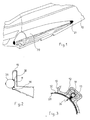
- Figure 1 illustrates a stern portion of a rigid hull 10 at which a tubular member 20 is fixed to the side flank of the hull.
- a corresponding tubular member 20 (not shown) is fixed to the opposite flank, such as to provide a system capable of ensuring improved performance in terms of protection and lateral stability.
- a hull with partial tubular members is thus provided.
- each tubular member 20 is fixed at a recessed housing 11 provided within the rigid structure of the hull 10.
- each tubular member 20 is removably fixed to the hull 10 through particular fixing means ensuring a strong retention.
- the fixing means comprise one or more longitudinal "sliding rods" 30, such as that represented in greater detail in the view from Figure 3.
- Each longitudinal sliding rod 30 is formed by a rope 31 made of a textile material, or in a rubber material which is optionally equipped with a metal insert, which is made integral to the tubular member 20 through a coating layer 32 of a material either consistent with or identical to the tubular member 20.
- the bond between the coating layer 32 and the outer surface of the tubular member 20 is preferably obtained by gluing the mutually contacting surfaces.
- Each sliding rod 30 is fitted within a guide element 12 integral with the hull 10 and provided with a groove 13 having such shape and size as to allow a sliding engagement of the sliding rod 30.
- the guide elements 12 are preferably arranged in the hull 10 in such a position as to allow a same tubular member 20 to be mounted indifferently to the right or left flanks of the hull.
- the tubular members 20 are made such as to be independently mounted to the left or right flanks of the same hull 10, with considerable advantages in terms of cost.
- Figure 4 shows the fixing of the front part of the tubular member 20, at which there is provided an end portion 21 fastened to the hull 10 by means of screws 22 and nuts 23 fitted within corresponding through holes 24 drilled in the same end portion 21.
- the front locking portion 21 of the tubular member 20 consists of a base element 40 made of rubber for an insert 41 made of metal or rigid plastic material to be incorporated therein.
- the rigid insert 41 can be either drowned in the rubber of the base element 40 ( Figure 5), or fitted therein and covered with a rubber layer ( Figure 6) fixed for example by gluing.
- the locking portion 21 provided with the rigid insert 41 enables the fixing to the hull 10 by means of the through screws 22 such that the heads of the screws do not protrude from the upper surface of the flank.
- the rigid insert 41 allows to support the tightening torque that would be otherwise unloaded to the rubber base element 40 which would collapse.
- the locking ensures that each tubular member 20 thus provided may not be inadvertedly released, even in case of boat capsizing.
- the present invention also provides particular advantages during manufacture, which advantages are underlined below with reference to Figures 7A-7C.
- Figure 7A there is schematically illustrated a section of a rigid hull 110 of the conventional type, i.e. without any tubular member
- Figure 7B is a schematic section view of a hull 210 with a sole tubular member of the conventional type, i.e. a tubular member 220 totally surrounding the perimeter of the hull. It should be understood that both hulls 110 and 210 cannot be obtained by the same mould.
- Figure 7C illustrates a hull 10 according to the present invention. From the mould 1 for a conventional rigid hull, of the type represented in Figure 7A, it is possible to obtain a hull with partial tubular members by simply providing suitable inserts 2 within the mould. The inserts 2, fixed from outside the mould 1 by removable means (not illustrated), will be extracted from the mould 1 together with the moulded piece and subsequently removed.
- the modular mould 1 indifferently allows to obtain a boat with a conventional rigid hull or with a RIB type hull, i.e. a boat prearranged for the fixing of a tubular member 20 or any other removable system (for example, fenders) or not.
- a mould 1 will be thus obtained which is prearranged for 'normal' laminations (to obtain conventional rigid hulls), or by using the suitable inserts 2, for laminations intended to obtain housings and guide elements which are suitable to allow the mounting of the tubular members 20.
- Both hull versions for one boat can be thus offered to the customers.
- the tubular member 20 comprises an inflatable casing 27 ( Figure 6) made of a flexible material.
- the connection between the casing 27 and the front locking portion 21 can be for example made by gluing at suitable depressions 28 formed on the outer surface of the base element 40 or the corresponding rubber layer coated thereon, such as to make the outer surface of the tubular member 20 smooth, or however without irregularities or steps.
- the tubular member 20 is preferably inflatable or deflatable as desired and the casing 27 is preferably made with one or more separate airtight chambers.
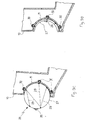
- FIG. 8 shows the stern portion according to a possible embodiment of the present invention, in which each of the flexible casings 27 of the tubular members 20 is partitioned into airtight chambers 27a-27d which are separated by suitable partition walls 25.
- each tubular member 20 can be carried out by using a single inflating valve 62 connected to a single pipe 60 crossing the partition walls 25 of the airtight chambers 27a-27d.
- the valve 62 is arranged aft of the respective tubular member 20, in such a position as to not interfere with the hull 10, whereas along the pipe 60 there are present non-return valves 61 (one for each chamber) to pneumatically isolate each chamber from the others.
- each chamber 27a-27d is provided with a respective air valve 63.
- This inflation/deflation system allows to separately and independently inflate and deflate each of the tubular members 20 while in motion, without any need to stop.
- inner elastic tension wires 29 suitable to limit the bulk thereof when it is deflated.
- the elastic tension wires 29 are arranged with an end thereof which is fastened to each of the sliding rods 30, whereas the other end of each of the elastic tension wires 29 is fastened to a protection profile 26 fixed outside the tubular member 20.
- the protection profile 26 is preferably made of a material having a greater hardness than the material of the inflatable casing 27, for example a rubber or plastic having a greater hardness than casing 27, and can be fixed to the casing for example by gluing.
- the casing 27 in a deflated condition does not droop, thus being instead retracted by the inner elastic tension wires 29 such as to occupy the recessed housing 11 of the flank of hull 10, i.e. the same "natural" housing of the tubular member 20 when in operative conditions.
- the particular nature of the materials composing the protection profile 26 and the arrangement of the elastic tension wires 29 facilitates the retraction of the casing 27 into the recessed housing 11.
- the elastic tension wires 29 which is indicated in Figures 9A and 9B is given by way of illustration only.
- the elastic tension wires 29 can also be fixed such as to obtain a sort of three-dimensional web, and thus not being necessarily fastened at the ends thereof to the sliding rods 30 and/or the protection profile 26.
- the protection profile 26 can also have a smaller sectional size and the retraction efficiency can be essentially delegated only to the geometrical arrangement of the elastic tension wires 29.
- the inner elastic tension wires 29 can be inserted within the inflatable casing 27 in an already pre-tensioned condition.
- the retracting means of casing 27 can however be made with a different inner tensioning system, for example by means of pulleys which are connected to one another through rigid or elastic cables.
- the remaining part of the hull, particularly the bow, being no longer interested by the presence of a sole complete tubular member, can be shaped such as to ensure further safety characteristics.
- the bow portion can be shaped such as to provide a so-called "anti-sink bow”.
- a possible embodiment of the bow portion of a hull 10 according to the present invention is illustrated by way of example in the Figures 10A-10C.
- the anti-sink bow which is represented herein is made by widening the upper part of a conventional pointed bow 51 such that the front end comprises flat surfaces 50, such as shown in the bottom plan view from Figure 10A. Consequently, the deck portion 55 is also widened in order to be joined to the widened surfaces 50.
- the junction of the bow widened end to the hull flank is provided by a convex surface 53 followed by a concave surface 54.
- the latter is upwardly joined, i.e. near the deck 55, to the side surface of the projecting portions 52 until the junction of the hull to the deck. All the surfaces described herein are directly obtained from the hull mould during manufacture.
- the bow shaped in this way is called "anti-sink” not because it ensures buoyancy with the damaged boat, either leaking or flooded by the waves, rather because it prevents the bow from sinking with very rough and head sea.
- the transversal surfaces 53 and 54 ensure the hydrodynamic lift should the bow temporarily sink in the water.
- an upward thrust is generated which causes the bow to emerge faster, thereby providing a safer and more stable boat.
Landscapes
- Chemical & Material Sciences (AREA)
- Engineering & Computer Science (AREA)
- Combustion & Propulsion (AREA)
- Mechanical Engineering (AREA)
- Ocean & Marine Engineering (AREA)
- Toys (AREA)
- Telescopes (AREA)
- Laminated Bodies (AREA)
- Earth Drilling (AREA)
- Preparation Of Compounds By Using Micro-Organisms (AREA)
- Saccharide Compounds (AREA)
- Agricultural Chemicals And Associated Chemicals (AREA)
- Rigid Pipes And Flexible Pipes (AREA)
Applications Claiming Priority (2)
| Application Number | Priority Date | Filing Date | Title |
|---|---|---|---|
| ITMI20031731 | 2003-09-10 | ||
| IT001731A ITMI20031731A1 (it) | 2003-09-10 | 2003-09-10 | Scafo per imbarcazioni. |
Publications (3)
| Publication Number | Publication Date |
|---|---|
| EP1514794A2 true EP1514794A2 (fr) | 2005-03-16 |
| EP1514794A3 EP1514794A3 (fr) | 2005-04-20 |
| EP1514794B1 EP1514794B1 (fr) | 2008-04-23 |
Family
ID=34131219
Family Applications (1)
| Application Number | Title | Priority Date | Filing Date |
|---|---|---|---|
| EP04021186A Expired - Lifetime EP1514794B1 (fr) | 2003-09-10 | 2004-09-07 | Coque de bateau |
Country Status (6)
| Country | Link |
|---|---|
| US (1) | US20050051075A1 (fr) |
| EP (1) | EP1514794B1 (fr) |
| CN (1) | CN1605544A (fr) |
| AT (1) | ATE393085T1 (fr) |
| DE (1) | DE602004013237T2 (fr) |
| IT (1) | ITMI20031731A1 (fr) |
Cited By (4)
| Publication number | Priority date | Publication date | Assignee | Title |
|---|---|---|---|---|
| EP1645500A1 (fr) * | 2004-10-08 | 2006-04-12 | Wings Aktiebolag | Bateau gonflable |
| ITRM20110356A1 (it) * | 2011-07-07 | 2013-01-08 | Icarus Internat S R L | "sistema modulare indipendente di controllo della navigazione" |
| WO2013173886A3 (fr) * | 2012-05-25 | 2014-04-10 | Nikolić Cvjetko | Dispositif de protection de coque contre des obstacles sous-marins |
| ITUB20155583A1 (it) * | 2015-11-13 | 2017-05-13 | Carmelo Marchetta | Scafo planante stabilizzato a sostentamento aeraulico (carena ad unghia) |
Families Citing this family (5)
| Publication number | Priority date | Publication date | Assignee | Title |
|---|---|---|---|---|
| FR2896227B1 (fr) * | 2006-01-13 | 2008-03-28 | Jean Luc Vanoise | Dispositif de protection d'une coque de bateau |
| US7971550B2 (en) * | 2008-05-30 | 2011-07-05 | Hansen John F | Rigid tube buoyancy assembly for boats |
| IT201700064166A1 (it) * | 2017-06-09 | 2018-12-09 | Adragna Yacht Design Studio Pte Ltd | Scafo per imbarcazione, procedimento per realizzarlo e relativa imbarcazione |
| CN110304197B (zh) * | 2019-06-21 | 2021-03-02 | 中船黄埔文冲船舶有限公司 | 一种甲板舷边结构及其线型放样方法 |
| CN110466682B (zh) * | 2019-08-22 | 2021-05-11 | 中船黄埔文冲船舶有限公司 | 一种圆弧过渡甲板的制作方法 |
Family Cites Families (14)
| Publication number | Priority date | Publication date | Assignee | Title |
|---|---|---|---|---|
| US2544599A (en) * | 1947-06-28 | 1951-03-06 | Keelen Festus Aeneas | Rowboat safety pontoon |
| US3566425A (en) * | 1969-09-10 | 1971-03-02 | Bonair Boats Inc | Floorboard apparatus for inflatable boats or the like |
| FR2292926A1 (fr) * | 1974-11-29 | 1976-06-25 | Lair Gilbert | Systeme de renforcement de la rigidite longitudinale des structures gonflables |
| US4416639A (en) * | 1981-06-22 | 1983-11-22 | Gillmer Thomas C | Manageable safety dinghy |
| GB8601401D0 (en) * | 1986-01-21 | 1986-02-26 | Task Force Boats Ltd | Rigid inflatable boat |
| US4962718A (en) * | 1988-04-27 | 1990-10-16 | Westfoil International | Hydrofoil propulsion system |
| US4938162A (en) * | 1988-09-30 | 1990-07-03 | Hanlon Frederick V | Inflatable power catamaran |
| US5617810A (en) * | 1995-06-07 | 1997-04-08 | Sauerwein; William D. | Compact semi-collapsible watercraft |
| CA2354229A1 (fr) * | 2000-07-28 | 2002-01-28 | Donald R. Redman | Vehicule amphibie equipe d'un flotteur pneumatique |
| US6419532B1 (en) * | 2000-09-01 | 2002-07-16 | Edward Bradish, Jr. | Jet-propelled watercraft |
| US20020056409A1 (en) * | 2000-11-14 | 2002-05-16 | Murphree Terry B. | Folding rigid inflatable boat system and method |
| US6470818B1 (en) * | 2001-04-10 | 2002-10-29 | Float Rail, Inc. | Automatic inflating watercraft flotation device |
| KR200242444Y1 (ko) * | 2001-05-17 | 2001-10-15 | 홍광선 | 조립식 고무보트 |
| US6869323B2 (en) * | 2002-08-08 | 2005-03-22 | Larry Norman | Pedal powered watercraft and equipment |
-
2003
- 2003-09-10 IT IT001731A patent/ITMI20031731A1/it unknown
-
2004
- 2004-09-07 DE DE602004013237T patent/DE602004013237T2/de not_active Expired - Lifetime
- 2004-09-07 AT AT04021186T patent/ATE393085T1/de not_active IP Right Cessation
- 2004-09-07 EP EP04021186A patent/EP1514794B1/fr not_active Expired - Lifetime
- 2004-09-09 US US10/936,710 patent/US20050051075A1/en not_active Abandoned
- 2004-09-10 CN CNA2004100899201A patent/CN1605544A/zh active Pending
Cited By (4)
| Publication number | Priority date | Publication date | Assignee | Title |
|---|---|---|---|---|
| EP1645500A1 (fr) * | 2004-10-08 | 2006-04-12 | Wings Aktiebolag | Bateau gonflable |
| ITRM20110356A1 (it) * | 2011-07-07 | 2013-01-08 | Icarus Internat S R L | "sistema modulare indipendente di controllo della navigazione" |
| WO2013173886A3 (fr) * | 2012-05-25 | 2014-04-10 | Nikolić Cvjetko | Dispositif de protection de coque contre des obstacles sous-marins |
| ITUB20155583A1 (it) * | 2015-11-13 | 2017-05-13 | Carmelo Marchetta | Scafo planante stabilizzato a sostentamento aeraulico (carena ad unghia) |
Also Published As
| Publication number | Publication date |
|---|---|
| DE602004013237T2 (de) | 2009-05-20 |
| CN1605544A (zh) | 2005-04-13 |
| DE602004013237D1 (de) | 2008-06-05 |
| EP1514794A3 (fr) | 2005-04-20 |
| ITMI20031731A1 (it) | 2005-03-11 |
| US20050051075A1 (en) | 2005-03-10 |
| EP1514794B1 (fr) | 2008-04-23 |
| ATE393085T1 (de) | 2008-05-15 |
Similar Documents
| Publication | Publication Date | Title |
|---|---|---|
| US4251893A (en) | Inflatable boat for high speed use | |
| EP1349772B1 (fr) | Bateau gonflable a coque rigide avec coussin en mousse | |
| CA2002030C (fr) | Embarcation gonflable a structure modulaire rigide | |
| EP1514794B1 (fr) | Coque de bateau | |
| US8286573B2 (en) | External inflatable keel for portable inflatable boats | |
| US20190263475A1 (en) | Inflatable watercraft and method of making same | |
| US5228407A (en) | Rigid inflatable boat | |
| US6371040B1 (en) | Combined foam and inflatable collar assemblies for watercraft | |
| JP3958046B2 (ja) | カヌー、カヌーのインフレータブルスキン、カヌーのフレーム及びカヌーの組立て方法 | |
| GB1574881A (en) | Dismantlable floating craft | |
| US6860220B2 (en) | Watercraft and inflatable flooring therefor | |
| US6460477B1 (en) | Sponson and rigid inflatable boat incorporating the same | |
| US11584486B2 (en) | Kayak type inflatable watercraft | |
| US4892055A (en) | Reinforced hull for a water craft | |
| US4750448A (en) | Semi-rigid pneumatic boat | |
| US7240634B1 (en) | Foldable rigid frame attachment system for portable inflatable pontoon boats | |
| US3611459A (en) | Composite boat | |
| US5313908A (en) | Car topable catamaran with collapsible frame and universal tiller/rudder-mast daggerboard mounting constructions | |
| US6668744B2 (en) | Vessel floatation aid | |
| KR100805333B1 (ko) | 평탄성을 갖는 공기 주입식 보트 및 그의 제조방법 | |
| US3955229A (en) | Rubber boat | |
| GB2152441A (en) | Inflatable vessels and sails | |
| GB2171652A (en) | Inflatable catamaran | |
| US9738357B2 (en) | Air and foam collar for watercraft | |
| KR101042259B1 (ko) | 인플래터블 카약 |
Legal Events
| Date | Code | Title | Description |
|---|---|---|---|
| PUAI | Public reference made under article 153(3) epc to a published international application that has entered the european phase |
Free format text: ORIGINAL CODE: 0009012 |
|
| PUAL | Search report despatched |
Free format text: ORIGINAL CODE: 0009013 |
|
| AK | Designated contracting states |
Kind code of ref document: A2 Designated state(s): AT BE BG CH CY CZ DE DK EE ES FI FR GB GR HU IE IT LI LU MC NL PL PT RO SE SI SK TR |
|
| AX | Request for extension of the european patent |
Extension state: AL HR LT LV MK |
|
| AK | Designated contracting states |
Kind code of ref document: A3 Designated state(s): AT BE BG CH CY CZ DE DK EE ES FI FR GB GR HU IE IT LI LU MC NL PL PT RO SE SI SK TR |
|
| AX | Request for extension of the european patent |
Extension state: AL HR LT LV MK |
|
| 17P | Request for examination filed |
Effective date: 20050922 |
|
| AKX | Designation fees paid |
Designated state(s): AT BE BG CH CY CZ DE DK EE ES FI FR GB GR HU IE IT LI LU MC NL PL PT RO SE SI SK TR |
|
| RIN1 | Information on inventor provided before grant (corrected) |
Inventor name: BUZZI, FABIO |
|
| GRAP | Despatch of communication of intention to grant a patent |
Free format text: ORIGINAL CODE: EPIDOSNIGR1 |
|
| GRAS | Grant fee paid |
Free format text: ORIGINAL CODE: EPIDOSNIGR3 |
|
| GRAA | (expected) grant |
Free format text: ORIGINAL CODE: 0009210 |
|
| AK | Designated contracting states |
Kind code of ref document: B1 Designated state(s): AT BE BG CH CY CZ DE DK EE ES FI FR GB GR HU IE IT LI LU MC NL PL PT RO SE SI SK TR |
|
| REG | Reference to a national code |
Ref country code: GB Ref legal event code: FG4D |
|
| REG | Reference to a national code |
Ref country code: CH Ref legal event code: EP |
|
| REF | Corresponds to: |
Ref document number: 602004013237 Country of ref document: DE Date of ref document: 20080605 Kind code of ref document: P |
|
| REG | Reference to a national code |
Ref country code: IE Ref legal event code: FG4D Free format text: LANGUAGE OF EP DOCUMENT: FRENCH |
|
| PG25 | Lapsed in a contracting state [announced via postgrant information from national office to epo] |
Ref country code: SI Free format text: LAPSE BECAUSE OF FAILURE TO SUBMIT A TRANSLATION OF THE DESCRIPTION OR TO PAY THE FEE WITHIN THE PRESCRIBED TIME-LIMIT Effective date: 20080423 |
|
| NLV1 | Nl: lapsed or annulled due to failure to fulfill the requirements of art. 29p and 29m of the patents act | ||
| PG25 | Lapsed in a contracting state [announced via postgrant information from national office to epo] |
Ref country code: FI Free format text: LAPSE BECAUSE OF FAILURE TO SUBMIT A TRANSLATION OF THE DESCRIPTION OR TO PAY THE FEE WITHIN THE PRESCRIBED TIME-LIMIT Effective date: 20080423 Ref country code: BG Free format text: LAPSE BECAUSE OF FAILURE TO SUBMIT A TRANSLATION OF THE DESCRIPTION OR TO PAY THE FEE WITHIN THE PRESCRIBED TIME-LIMIT Effective date: 20080723 Ref country code: NL Free format text: LAPSE BECAUSE OF FAILURE TO SUBMIT A TRANSLATION OF THE DESCRIPTION OR TO PAY THE FEE WITHIN THE PRESCRIBED TIME-LIMIT Effective date: 20080423 Ref country code: ES Free format text: LAPSE BECAUSE OF FAILURE TO SUBMIT A TRANSLATION OF THE DESCRIPTION OR TO PAY THE FEE WITHIN THE PRESCRIBED TIME-LIMIT Effective date: 20080803 Ref country code: PT Free format text: LAPSE BECAUSE OF FAILURE TO SUBMIT A TRANSLATION OF THE DESCRIPTION OR TO PAY THE FEE WITHIN THE PRESCRIBED TIME-LIMIT Effective date: 20080923 |
|
| PG25 | Lapsed in a contracting state [announced via postgrant information from national office to epo] |
Ref country code: PL Free format text: LAPSE BECAUSE OF FAILURE TO SUBMIT A TRANSLATION OF THE DESCRIPTION OR TO PAY THE FEE WITHIN THE PRESCRIBED TIME-LIMIT Effective date: 20080423 Ref country code: AT Free format text: LAPSE BECAUSE OF FAILURE TO SUBMIT A TRANSLATION OF THE DESCRIPTION OR TO PAY THE FEE WITHIN THE PRESCRIBED TIME-LIMIT Effective date: 20080423 |
|
| ET | Fr: translation filed | ||
| PG25 | Lapsed in a contracting state [announced via postgrant information from national office to epo] |
Ref country code: CZ Free format text: LAPSE BECAUSE OF FAILURE TO SUBMIT A TRANSLATION OF THE DESCRIPTION OR TO PAY THE FEE WITHIN THE PRESCRIBED TIME-LIMIT Effective date: 20080423 Ref country code: SE Free format text: LAPSE BECAUSE OF FAILURE TO SUBMIT A TRANSLATION OF THE DESCRIPTION OR TO PAY THE FEE WITHIN THE PRESCRIBED TIME-LIMIT Effective date: 20080723 Ref country code: DK Free format text: LAPSE BECAUSE OF FAILURE TO SUBMIT A TRANSLATION OF THE DESCRIPTION OR TO PAY THE FEE WITHIN THE PRESCRIBED TIME-LIMIT Effective date: 20080423 |
|
| PG25 | Lapsed in a contracting state [announced via postgrant information from national office to epo] |
Ref country code: SK Free format text: LAPSE BECAUSE OF FAILURE TO SUBMIT A TRANSLATION OF THE DESCRIPTION OR TO PAY THE FEE WITHIN THE PRESCRIBED TIME-LIMIT Effective date: 20080423 Ref country code: RO Free format text: LAPSE BECAUSE OF FAILURE TO SUBMIT A TRANSLATION OF THE DESCRIPTION OR TO PAY THE FEE WITHIN THE PRESCRIBED TIME-LIMIT Effective date: 20080423 Ref country code: BE Free format text: LAPSE BECAUSE OF FAILURE TO SUBMIT A TRANSLATION OF THE DESCRIPTION OR TO PAY THE FEE WITHIN THE PRESCRIBED TIME-LIMIT Effective date: 20080423 |
|
| PLBE | No opposition filed within time limit |
Free format text: ORIGINAL CODE: 0009261 |
|
| STAA | Information on the status of an ep patent application or granted ep patent |
Free format text: STATUS: NO OPPOSITION FILED WITHIN TIME LIMIT |
|
| 26N | No opposition filed |
Effective date: 20090126 |
|
| PG25 | Lapsed in a contracting state [announced via postgrant information from national office to epo] |
Ref country code: MC Free format text: LAPSE BECAUSE OF NON-PAYMENT OF DUE FEES Effective date: 20080930 Ref country code: EE Free format text: LAPSE BECAUSE OF FAILURE TO SUBMIT A TRANSLATION OF THE DESCRIPTION OR TO PAY THE FEE WITHIN THE PRESCRIBED TIME-LIMIT Effective date: 20080423 |
|
| REG | Reference to a national code |
Ref country code: CH Ref legal event code: PL |
|
| REG | Reference to a national code |
Ref country code: IE Ref legal event code: MM4A |
|
| PG25 | Lapsed in a contracting state [announced via postgrant information from national office to epo] |
Ref country code: IE Free format text: LAPSE BECAUSE OF NON-PAYMENT OF DUE FEES Effective date: 20080907 |
|
| PG25 | Lapsed in a contracting state [announced via postgrant information from national office to epo] |
Ref country code: LI Free format text: LAPSE BECAUSE OF NON-PAYMENT OF DUE FEES Effective date: 20080930 Ref country code: CH Free format text: LAPSE BECAUSE OF NON-PAYMENT OF DUE FEES Effective date: 20080930 |
|
| PG25 | Lapsed in a contracting state [announced via postgrant information from national office to epo] |
Ref country code: HU Free format text: LAPSE BECAUSE OF FAILURE TO SUBMIT A TRANSLATION OF THE DESCRIPTION OR TO PAY THE FEE WITHIN THE PRESCRIBED TIME-LIMIT Effective date: 20081024 Ref country code: LU Free format text: LAPSE BECAUSE OF NON-PAYMENT OF DUE FEES Effective date: 20080907 Ref country code: CY Free format text: LAPSE BECAUSE OF FAILURE TO SUBMIT A TRANSLATION OF THE DESCRIPTION OR TO PAY THE FEE WITHIN THE PRESCRIBED TIME-LIMIT Effective date: 20080423 |
|
| PG25 | Lapsed in a contracting state [announced via postgrant information from national office to epo] |
Ref country code: TR Free format text: LAPSE BECAUSE OF FAILURE TO SUBMIT A TRANSLATION OF THE DESCRIPTION OR TO PAY THE FEE WITHIN THE PRESCRIBED TIME-LIMIT Effective date: 20080423 |
|
| PG25 | Lapsed in a contracting state [announced via postgrant information from national office to epo] |
Ref country code: GR Free format text: LAPSE BECAUSE OF FAILURE TO SUBMIT A TRANSLATION OF THE DESCRIPTION OR TO PAY THE FEE WITHIN THE PRESCRIBED TIME-LIMIT Effective date: 20080724 |
|
| REG | Reference to a national code |
Ref country code: DE Ref legal event code: R082 Ref document number: 602004013237 Country of ref document: DE Representative=s name: GODEMEYER BLUM LENZE PARTNERSCHAFT, PATENTANWA, DE Ref country code: DE Ref legal event code: R082 Ref document number: 602004013237 Country of ref document: DE Representative=s name: GODEMEYER BLUM LENZE PATENTANWAELTE, PARTNERSC, DE |
|
| REG | Reference to a national code |
Ref country code: FR Ref legal event code: PLFP Year of fee payment: 12 |
|
| REG | Reference to a national code |
Ref country code: FR Ref legal event code: PLFP Year of fee payment: 13 |
|
| REG | Reference to a national code |
Ref country code: FR Ref legal event code: PLFP Year of fee payment: 14 |
|
| REG | Reference to a national code |
Ref country code: FR Ref legal event code: PLFP Year of fee payment: 15 |
|
| PGFP | Annual fee paid to national office [announced via postgrant information from national office to epo] |
Ref country code: IT Payment date: 20230913 Year of fee payment: 20 Ref country code: GB Payment date: 20230913 Year of fee payment: 20 |
|
| P01 | Opt-out of the competence of the unified patent court (upc) registered |
Effective date: 20231003 |
|
| PGFP | Annual fee paid to national office [announced via postgrant information from national office to epo] |
Ref country code: FR Payment date: 20230816 Year of fee payment: 20 Ref country code: DE Payment date: 20230901 Year of fee payment: 20 |
|
| REG | Reference to a national code |
Ref country code: DE Ref legal event code: R071 Ref document number: 602004013237 Country of ref document: DE |
|
| REG | Reference to a national code |
Ref country code: GB Ref legal event code: PE20 Expiry date: 20240906 |
|
| PG25 | Lapsed in a contracting state [announced via postgrant information from national office to epo] |
Ref country code: GB Free format text: LAPSE BECAUSE OF EXPIRATION OF PROTECTION Effective date: 20240906 |
|
| PG25 | Lapsed in a contracting state [announced via postgrant information from national office to epo] |
Ref country code: GB Free format text: LAPSE BECAUSE OF EXPIRATION OF PROTECTION Effective date: 20240906 |