EP1514917A1 - Adsorptionsentschwefelungsmittel zur entschwefelung einer erdölfraktion und entschwefelungsverfahren, bei dem dieses zur anwendung kommt - Google Patents
Adsorptionsentschwefelungsmittel zur entschwefelung einer erdölfraktion und entschwefelungsverfahren, bei dem dieses zur anwendung kommt Download PDFInfo
- Publication number
- EP1514917A1 EP1514917A1 EP03733022A EP03733022A EP1514917A1 EP 1514917 A1 EP1514917 A1 EP 1514917A1 EP 03733022 A EP03733022 A EP 03733022A EP 03733022 A EP03733022 A EP 03733022A EP 1514917 A1 EP1514917 A1 EP 1514917A1
- Authority
- EP
- European Patent Office
- Prior art keywords
- gas oil
- adsorptive desulfurization
- desulfurization agent
- distillate products
- sulfur
- Prior art date
- Legal status (The legal status is an assumption and is not a legal conclusion. Google has not performed a legal analysis and makes no representation as to the accuracy of the status listed.)
- Withdrawn
Links
Images




Classifications
-
- B—PERFORMING OPERATIONS; TRANSPORTING
- B01—PHYSICAL OR CHEMICAL PROCESSES OR APPARATUS IN GENERAL
- B01J—CHEMICAL OR PHYSICAL PROCESSES, e.g. CATALYSIS OR COLLOID CHEMISTRY; THEIR RELEVANT APPARATUS
- B01J20/00—Solid sorbent compositions or filter aid compositions; Sorbents for chromatography; Processes for preparing, regenerating or reactivating thereof
- B01J20/02—Solid sorbent compositions or filter aid compositions; Sorbents for chromatography; Processes for preparing, regenerating or reactivating thereof comprising inorganic material
- B01J20/10—Solid sorbent compositions or filter aid compositions; Sorbents for chromatography; Processes for preparing, regenerating or reactivating thereof comprising inorganic material comprising silica or silicate
- B01J20/16—Alumino-silicates
- B01J20/18—Synthetic zeolitic molecular sieves
-
- B—PERFORMING OPERATIONS; TRANSPORTING
- B01—PHYSICAL OR CHEMICAL PROCESSES OR APPARATUS IN GENERAL
- B01J—CHEMICAL OR PHYSICAL PROCESSES, e.g. CATALYSIS OR COLLOID CHEMISTRY; THEIR RELEVANT APPARATUS
- B01J20/00—Solid sorbent compositions or filter aid compositions; Sorbents for chromatography; Processes for preparing, regenerating or reactivating thereof
- B01J20/02—Solid sorbent compositions or filter aid compositions; Sorbents for chromatography; Processes for preparing, regenerating or reactivating thereof comprising inorganic material
- B01J20/10—Solid sorbent compositions or filter aid compositions; Sorbents for chromatography; Processes for preparing, regenerating or reactivating thereof comprising inorganic material comprising silica or silicate
- B01J20/16—Alumino-silicates
- B01J20/165—Natural alumino-silicates, e.g. zeolites
-
- B—PERFORMING OPERATIONS; TRANSPORTING
- B01—PHYSICAL OR CHEMICAL PROCESSES OR APPARATUS IN GENERAL
- B01J—CHEMICAL OR PHYSICAL PROCESSES, e.g. CATALYSIS OR COLLOID CHEMISTRY; THEIR RELEVANT APPARATUS
- B01J20/00—Solid sorbent compositions or filter aid compositions; Sorbents for chromatography; Processes for preparing, regenerating or reactivating thereof
- B01J20/02—Solid sorbent compositions or filter aid compositions; Sorbents for chromatography; Processes for preparing, regenerating or reactivating thereof comprising inorganic material
- B01J20/20—Solid sorbent compositions or filter aid compositions; Sorbents for chromatography; Processes for preparing, regenerating or reactivating thereof comprising inorganic material comprising free carbon; comprising carbon obtained by carbonising processes
-
- B—PERFORMING OPERATIONS; TRANSPORTING
- B01—PHYSICAL OR CHEMICAL PROCESSES OR APPARATUS IN GENERAL
- B01J—CHEMICAL OR PHYSICAL PROCESSES, e.g. CATALYSIS OR COLLOID CHEMISTRY; THEIR RELEVANT APPARATUS
- B01J20/00—Solid sorbent compositions or filter aid compositions; Sorbents for chromatography; Processes for preparing, regenerating or reactivating thereof
- B01J20/28—Solid sorbent compositions or filter aid compositions; Sorbents for chromatography; Processes for preparing, regenerating or reactivating thereof characterised by their form or physical properties
- B01J20/28014—Solid sorbent compositions or filter aid compositions; Sorbents for chromatography; Processes for preparing, regenerating or reactivating thereof characterised by their form or physical properties characterised by their form
- B01J20/28023—Fibres or filaments
-
- B—PERFORMING OPERATIONS; TRANSPORTING
- B01—PHYSICAL OR CHEMICAL PROCESSES OR APPARATUS IN GENERAL
- B01J—CHEMICAL OR PHYSICAL PROCESSES, e.g. CATALYSIS OR COLLOID CHEMISTRY; THEIR RELEVANT APPARATUS
- B01J20/00—Solid sorbent compositions or filter aid compositions; Sorbents for chromatography; Processes for preparing, regenerating or reactivating thereof
- B01J20/28—Solid sorbent compositions or filter aid compositions; Sorbents for chromatography; Processes for preparing, regenerating or reactivating thereof characterised by their form or physical properties
- B01J20/28054—Solid sorbent compositions or filter aid compositions; Sorbents for chromatography; Processes for preparing, regenerating or reactivating thereof characterised by their form or physical properties characterised by their surface properties or porosity
- B01J20/28057—Surface area, e.g. B.E.T specific surface area
-
- B—PERFORMING OPERATIONS; TRANSPORTING
- B01—PHYSICAL OR CHEMICAL PROCESSES OR APPARATUS IN GENERAL
- B01J—CHEMICAL OR PHYSICAL PROCESSES, e.g. CATALYSIS OR COLLOID CHEMISTRY; THEIR RELEVANT APPARATUS
- B01J20/00—Solid sorbent compositions or filter aid compositions; Sorbents for chromatography; Processes for preparing, regenerating or reactivating thereof
- B01J20/28—Solid sorbent compositions or filter aid compositions; Sorbents for chromatography; Processes for preparing, regenerating or reactivating thereof characterised by their form or physical properties
- B01J20/28054—Solid sorbent compositions or filter aid compositions; Sorbents for chromatography; Processes for preparing, regenerating or reactivating thereof characterised by their form or physical properties characterised by their surface properties or porosity
- B01J20/28069—Pore volume, e.g. total pore volume, mesopore volume, micropore volume
-
- B—PERFORMING OPERATIONS; TRANSPORTING
- B01—PHYSICAL OR CHEMICAL PROCESSES OR APPARATUS IN GENERAL
- B01J—CHEMICAL OR PHYSICAL PROCESSES, e.g. CATALYSIS OR COLLOID CHEMISTRY; THEIR RELEVANT APPARATUS
- B01J20/00—Solid sorbent compositions or filter aid compositions; Sorbents for chromatography; Processes for preparing, regenerating or reactivating thereof
- B01J20/30—Processes for preparing, regenerating, or reactivating
- B01J20/34—Regenerating or reactivating
- B01J20/3408—Regenerating or reactivating of aluminosilicate molecular sieves
-
- B—PERFORMING OPERATIONS; TRANSPORTING
- B01—PHYSICAL OR CHEMICAL PROCESSES OR APPARATUS IN GENERAL
- B01J—CHEMICAL OR PHYSICAL PROCESSES, e.g. CATALYSIS OR COLLOID CHEMISTRY; THEIR RELEVANT APPARATUS
- B01J20/00—Solid sorbent compositions or filter aid compositions; Sorbents for chromatography; Processes for preparing, regenerating or reactivating thereof
- B01J20/30—Processes for preparing, regenerating, or reactivating
- B01J20/34—Regenerating or reactivating
- B01J20/3416—Regenerating or reactivating of sorbents or filter aids comprising free carbon, e.g. activated carbon
-
- B—PERFORMING OPERATIONS; TRANSPORTING
- B01—PHYSICAL OR CHEMICAL PROCESSES OR APPARATUS IN GENERAL
- B01J—CHEMICAL OR PHYSICAL PROCESSES, e.g. CATALYSIS OR COLLOID CHEMISTRY; THEIR RELEVANT APPARATUS
- B01J20/00—Solid sorbent compositions or filter aid compositions; Sorbents for chromatography; Processes for preparing, regenerating or reactivating thereof
- B01J20/30—Processes for preparing, regenerating, or reactivating
- B01J20/34—Regenerating or reactivating
- B01J20/345—Regenerating or reactivating using a particular desorbing compound or mixture
- B01J20/3475—Regenerating or reactivating using a particular desorbing compound or mixture in the liquid phase
-
- B—PERFORMING OPERATIONS; TRANSPORTING
- B01—PHYSICAL OR CHEMICAL PROCESSES OR APPARATUS IN GENERAL
- B01J—CHEMICAL OR PHYSICAL PROCESSES, e.g. CATALYSIS OR COLLOID CHEMISTRY; THEIR RELEVANT APPARATUS
- B01J20/00—Solid sorbent compositions or filter aid compositions; Sorbents for chromatography; Processes for preparing, regenerating or reactivating thereof
- B01J20/30—Processes for preparing, regenerating, or reactivating
- B01J20/34—Regenerating or reactivating
- B01J20/3483—Regenerating or reactivating by thermal treatment not covered by groups B01J20/3441 - B01J20/3475, e.g. by heating or cooling
-
- C—CHEMISTRY; METALLURGY
- C10—PETROLEUM, GAS OR COKE INDUSTRIES; TECHNICAL GASES CONTAINING CARBON MONOXIDE; FUELS; LUBRICANTS; PEAT
- C10G—CRACKING HYDROCARBON OILS; PRODUCTION OF LIQUID HYDROCARBON MIXTURES, e.g. BY DESTRUCTIVE HYDROGENATION, OLIGOMERISATION, POLYMERISATION; RECOVERY OF HYDROCARBON OILS FROM OIL-SHALE, OIL-SAND, OR GASES; REFINING MIXTURES MAINLY CONSISTING OF HYDROCARBONS; REFORMING OF NAPHTHA; MINERAL WAXES
- C10G25/00—Refining of hydrocarbon oils in the absence of hydrogen, with solid sorbents
- C10G25/003—Specific sorbent material, not covered by C10G25/02 or C10G25/03
-
- B—PERFORMING OPERATIONS; TRANSPORTING
- B01—PHYSICAL OR CHEMICAL PROCESSES OR APPARATUS IN GENERAL
- B01J—CHEMICAL OR PHYSICAL PROCESSES, e.g. CATALYSIS OR COLLOID CHEMISTRY; THEIR RELEVANT APPARATUS
- B01J2220/00—Aspects relating to sorbent materials
- B01J2220/40—Aspects relating to the composition of sorbent or filter aid materials
- B01J2220/42—Materials comprising a mixture of inorganic materials
-
- B—PERFORMING OPERATIONS; TRANSPORTING
- B01—PHYSICAL OR CHEMICAL PROCESSES OR APPARATUS IN GENERAL
- B01J—CHEMICAL OR PHYSICAL PROCESSES, e.g. CATALYSIS OR COLLOID CHEMISTRY; THEIR RELEVANT APPARATUS
- B01J2220/00—Aspects relating to sorbent materials
- B01J2220/50—Aspects relating to the use of sorbent or filter aid materials
- B01J2220/60—Use in several different columns
- B01J2220/606—Use in several different columns parallel disposed columns
-
- C—CHEMISTRY; METALLURGY
- C10—PETROLEUM, GAS OR COKE INDUSTRIES; TECHNICAL GASES CONTAINING CARBON MONOXIDE; FUELS; LUBRICANTS; PEAT
- C10G—CRACKING HYDROCARBON OILS; PRODUCTION OF LIQUID HYDROCARBON MIXTURES, e.g. BY DESTRUCTIVE HYDROGENATION, OLIGOMERISATION, POLYMERISATION; RECOVERY OF HYDROCARBON OILS FROM OIL-SHALE, OIL-SAND, OR GASES; REFINING MIXTURES MAINLY CONSISTING OF HYDROCARBONS; REFORMING OF NAPHTHA; MINERAL WAXES
- C10G2300/00—Aspects relating to hydrocarbon processing covered by groups C10G1/00 - C10G99/00
- C10G2300/10—Feedstock materials
- C10G2300/1037—Hydrocarbon fractions
- C10G2300/104—Light gasoline having a boiling range of about 20 - 100 °C
-
- C—CHEMISTRY; METALLURGY
- C10—PETROLEUM, GAS OR COKE INDUSTRIES; TECHNICAL GASES CONTAINING CARBON MONOXIDE; FUELS; LUBRICANTS; PEAT
- C10G—CRACKING HYDROCARBON OILS; PRODUCTION OF LIQUID HYDROCARBON MIXTURES, e.g. BY DESTRUCTIVE HYDROGENATION, OLIGOMERISATION, POLYMERISATION; RECOVERY OF HYDROCARBON OILS FROM OIL-SHALE, OIL-SAND, OR GASES; REFINING MIXTURES MAINLY CONSISTING OF HYDROCARBONS; REFORMING OF NAPHTHA; MINERAL WAXES
- C10G2300/00—Aspects relating to hydrocarbon processing covered by groups C10G1/00 - C10G99/00
- C10G2300/10—Feedstock materials
- C10G2300/1037—Hydrocarbon fractions
- C10G2300/1044—Heavy gasoline or naphtha having a boiling range of about 100 - 180 °C
-
- C—CHEMISTRY; METALLURGY
- C10—PETROLEUM, GAS OR COKE INDUSTRIES; TECHNICAL GASES CONTAINING CARBON MONOXIDE; FUELS; LUBRICANTS; PEAT
- C10G—CRACKING HYDROCARBON OILS; PRODUCTION OF LIQUID HYDROCARBON MIXTURES, e.g. BY DESTRUCTIVE HYDROGENATION, OLIGOMERISATION, POLYMERISATION; RECOVERY OF HYDROCARBON OILS FROM OIL-SHALE, OIL-SAND, OR GASES; REFINING MIXTURES MAINLY CONSISTING OF HYDROCARBONS; REFORMING OF NAPHTHA; MINERAL WAXES
- C10G2300/00—Aspects relating to hydrocarbon processing covered by groups C10G1/00 - C10G99/00
- C10G2300/10—Feedstock materials
- C10G2300/1037—Hydrocarbon fractions
- C10G2300/1048—Middle distillates
- C10G2300/1059—Gasoil having a boiling range of about 330 - 427 °C
-
- C—CHEMISTRY; METALLURGY
- C10—PETROLEUM, GAS OR COKE INDUSTRIES; TECHNICAL GASES CONTAINING CARBON MONOXIDE; FUELS; LUBRICANTS; PEAT
- C10G—CRACKING HYDROCARBON OILS; PRODUCTION OF LIQUID HYDROCARBON MIXTURES, e.g. BY DESTRUCTIVE HYDROGENATION, OLIGOMERISATION, POLYMERISATION; RECOVERY OF HYDROCARBON OILS FROM OIL-SHALE, OIL-SAND, OR GASES; REFINING MIXTURES MAINLY CONSISTING OF HYDROCARBONS; REFORMING OF NAPHTHA; MINERAL WAXES
- C10G2300/00—Aspects relating to hydrocarbon processing covered by groups C10G1/00 - C10G99/00
- C10G2300/20—Characteristics of the feedstock or the products
- C10G2300/201—Impurities
- C10G2300/202—Heteroatoms content, i.e. S, N, O, P
-
- C—CHEMISTRY; METALLURGY
- C10—PETROLEUM, GAS OR COKE INDUSTRIES; TECHNICAL GASES CONTAINING CARBON MONOXIDE; FUELS; LUBRICANTS; PEAT
- C10G—CRACKING HYDROCARBON OILS; PRODUCTION OF LIQUID HYDROCARBON MIXTURES, e.g. BY DESTRUCTIVE HYDROGENATION, OLIGOMERISATION, POLYMERISATION; RECOVERY OF HYDROCARBON OILS FROM OIL-SHALE, OIL-SAND, OR GASES; REFINING MIXTURES MAINLY CONSISTING OF HYDROCARBONS; REFORMING OF NAPHTHA; MINERAL WAXES
- C10G2400/00—Products obtained by processes covered by groups C10G9/00 - C10G69/14
- C10G2400/02—Gasoline
-
- C—CHEMISTRY; METALLURGY
- C10—PETROLEUM, GAS OR COKE INDUSTRIES; TECHNICAL GASES CONTAINING CARBON MONOXIDE; FUELS; LUBRICANTS; PEAT
- C10G—CRACKING HYDROCARBON OILS; PRODUCTION OF LIQUID HYDROCARBON MIXTURES, e.g. BY DESTRUCTIVE HYDROGENATION, OLIGOMERISATION, POLYMERISATION; RECOVERY OF HYDROCARBON OILS FROM OIL-SHALE, OIL-SAND, OR GASES; REFINING MIXTURES MAINLY CONSISTING OF HYDROCARBONS; REFORMING OF NAPHTHA; MINERAL WAXES
- C10G2400/00—Products obtained by processes covered by groups C10G9/00 - C10G69/14
- C10G2400/06—Gasoil
Definitions
- the present invention relates to an adsorptive desulfurization agent for adsorbing and removing sulfur compounds contained in petroleum distillate products, especially gas oil distillate products to be used as petroleum-based liquid fuel oils.
- the present invention also relates to a method for producing gas oil by using the adsorptive desulfurization agent, and the gas oil produced by the production method.
- the sulfur content contained in gasoline and gas oil may be regulated to be not more than 10 ppm in near future.
- any petroleum-based liquid fuel oil which has a lower sulfur content, may be possibly demanded as a result of the widespread use of the fuel cell for automobiles or the like which carry the fuel cell of the onboard reforming type. Therefore, at present, the desulfurization technique, which is required to obtain any petroleum-based fuel oil having an extremely low sulfur content, is vigorously investigated at present.
- the method which has been hitherto used as the desulfurization technique for the gas oil, includes the hydrodesulfurization method.
- the reaction temperature in order that the gas oil is desulfurized to have a low sulfur concentration of not more than 15 ppm by using the hydrodesulfurization method, it is necessary to raise the reaction temperature. If the reaction temperature is raised, a problem arises such that the color of the gas oil product is deteriorated.
- a method has been suggested as a method for improving the color of the gas oil, in which the gas oil distillate products having the deteriorated color are brought into contact with activated carbon (see, for example, Japanese Patent Application Laid-open No. 6-136370, pp. 1-2 and Japanese Patent Application Laid-open No. 2000-192054, pp. 3-6).
- PAH'S polycyclic aromatic hydrocarbon chemicals
- the present invention solves the problems involved in the conventional technique described above, a first object of which is to provide an adsorptive desulfurization agent and a method for desulfurizing petroleum distillate products using the adsorptive desulfurization agent which make it possible to remove the sulfur content from the petroleum distillate products sufficiently and especially to be not more than 10 ppm at relatively low equipment cost and running cost.
- a second object of the present invention is to provide a method for producing gas oil in which not only the sulfur content but also PAH'S are reduced.
- a third object of the present invention is to provide an adsorptive desulfurization agent and a method for producing gas oil using the same which make it possible to selectively remove sulfur compounds such as 4,6-DMDBT difficult to be desulfurized from petroleum distillate products.
- an adsorptive desulfurization agent comprising a carbon material having a specific surface area of not less than 500 m 2 /g, wherein organic sulfur compounds, which are contained in petroleum distillate products, are adsorbed by the adsorptive desulfurization agent.
- the inventors have used the adsorptive desulfurization agent composed of the carbon material having the specific surface area of not less than 500 m 2 /g in place of the hydrodesulfurization catalyst in the desulfurization process for petroleum distillate products. Accordingly, the compounds such as 4,6-DMDBT, which are hardly desulfurized, are selectively removed. As a result, the inventors have successfully lowered the sulfur content in the petroleum distillate products to an extremely low level, i.e., not more than 10 ppm. Further, the inventors have found out the fact that the adsorptive desulfurization agent of the present invention makes it possible to remarkably lower the PAH'S concentration in the petroleum distillate products by selectively adsorbing PAH'S.
- activated carbon fiber having a specific surface area of not less than 1,000 m 2 /g and especially 2,000 m 2 /g and an average length of not less than 100 ⁇ m and more preferably not less than 1 mm is used as the carbon material.
- the activated carbon fiber is used for the adsorptive desulfurization agent, it is possible to further increase the adsorption capacity, because the activated carbon fiber has pores extended in the radial directions of the fiber.
- the activated carbon fiber in which a large amount of mesopores having pore diameters of not less than 10 angstroms is presented, is preferably used, because the adsorption speed is high.
- the adsorptive desulfurization according to the present invention is principally based on the physical adsorption. Therefore, the adsorptive desulfurization can be carried out in a liquid state and at a low temperature, preferably at a temperature of not more than 100 °C.
- the activated carbon fiber hardly outflows from the adsorption vessel (tower), and the differential pressure is scarcely varied in the adsorption vessel. Therefore, the activated carbon fiber is preferred in view of the operation as well.
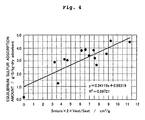
- the inventors have focused on the micropore specific surface area and the mesopore average pore diameter as parameters for the adsorptive desulfurization agent to affect the desulfurization characteristics, and found that the adsorption performance is remarkably improved when the value of the product of both the micropore specific surface area and the mesopore average pore diameter, i.e., Smicro x 2 x Vext/Sext is not less than 3.0 cm 3 /g and preferably not less than 5.0 cm 3 /g.
- the adsorptive desulfurization agent for the sulfur compounds such as hydrogen sulfide include activated carbon, inorganic porous materials such as zeolite and alumina, metals such as nickel, and composites thereof.
- the activated carbon has a small adsorption capacity for the sulfur compounds, and the activated carbon have no sufficient performance as the adsorptive desulfurization agent.
- those based on zeolite are predominantly used in the gas system.
- the carbon material having the specified specific surface area especially the activated carbon fiber, has the excellent adsorptive desulfurization performance with respect to the organic sulfur compounds, especially thiophene, benzothiophene, and dibenzothiophene.
- the adsorptive desulfurization agent of the present invention it is preferable that the petroleum distillate products, which are brought into contact with the adsorptive desulfurization agent, preferably contain major components of hydrocarbons having boiling points of 30 to 400 °C, and it is preferable that the sulfur content in the petroleum distillate products is not more than 200 ppm.
- the adsorptive desulfurization agent further contains a zeolite component.
- a method for desulfurizing petroleum distillate products comprising a step of bringing petroleum distillate products containing organic sulfur compounds into contact with an adsorptive desulfurization agent containing a carbon material having a specific surface area of not less than 500 m 2 /g.
- the petroleum distillate products are brought into contact with the adsorptive desulfurization agent in a liquid phase state.
- the adsorptive desulfurization agent is brought into contact with the petroleum distillate products at a temperature of not more than 100 °C.
- the adsorptive desulfurization agent further contains a zeolite component.
- the desulfurization method of the present invention further comprises a step of desorbing the organic sulfur compounds by heating the adsorptive desulfurization agent in a non-oxidizing atmosphere to regenerate the adsorptive desulfurization agent after bringing the petroleum distillate products into contact with the adsorptive desulfurization agent to effect the desulfurization, and a step of bringing the petroleum distillate products containing the organic sulfur compounds into contact with the regenerated adsorptive desulfurization agent.
- the adsorptive desulfurization agent after the adsorptive desulfurization can be repeatedly used by effecting the desorption and the regeneration with ease, for example, by the washing with a solvent such as toluene, alcohol, and acetone, the heating in a nitrogen atmosphere, and the heating under a reduced pressure.
- the regeneration can be sufficiently performed in a short period of time by effecting the heating in a non-oxidizing atmosphere (usually in a nitrogen atmosphere) and/or under a reduced pressure.
- water or steam as a heating source, although water or steam does not directly function as any desorbing agent or desorbent.
- a method for producing gas oil comprising an adsorptive desulfurization step of bringing gas oil distillate products in a liquid phase state containing sulfur contents of not more than 500 ppm into contact with an adsorptive desulfurization agent which comprises a carbon material having a specific surface area of not less than 500 m 2 /g and which adsorbs sulfur compounds contained in the gas oil distillate products; and a desorption regeneration step of washing the adsorptive desulfurization agent with an aromatic solvent to regenerate the adsorptive desulfurization agent.
- a gas oil which is obtained with the inventive method wherein a sulfur concentration is not more than 15 ppm, a ratio of sulfur of 4,6-dimethylbenzothiophene to a total sulfur content is not more than 10 %, and a 90 % distillation temperature is not less than 310 °C; a gas oil wherein a sulfur concentration is not more than 15 ppm, a ratio of aromatic compounds having two or more rings to a total aromatic compound content is not more than 7 %, and a 90 % distillation temperature is not less than 310 °C; or a gas oil wherein a sulfur concentration is not more than 15 ppm, a ratio of aromatic compounds having three rings to a total aromatic compound content is less than 0.5 %, and a 90 % distillation temperature is not less than 310 °C.
- the adsorptive desulfurization agent of the present invention preferably contains, for example, not less than 80 % by weight of the major component of the carbon material such as the activated carbon.
- the adsorptive desulfurization agent of the present invention may contain other components, for example, a zeolite component as described later on.
- the specific surface area can be measured by the so-called the nitrogen adsorption method.
- the activated carbon is a carbon material in which the pore structure is developed.
- the activated carbon is widely used industrially as adsorptive desulfurization agents and catalyst carriers.
- the carbon material which exhibits the adsorption activity naturally as anthracite as it is, is also known.
- the activated carbon is produced such that an activated carbon raw material as an organic matter (carbonaceous substance) is carbonized, followed by being activated, if necessary.
- the production method is not specifically limited.
- the production condition differs depending on the type of the raw material.
- Those usable as the raw material include, for example, plant wood, sawdust, coconut husk, and pulp spent liquor as well as fossil fuel-based materials such as petroleum heavy oil, and pitch and coke obtained by pyrolysis of the above.
- Starting raw materials for the activated carbon fiber include fibers obtained by spinning synthetic polymers, tar pitches, and petroleum-based pitches. The coal is classified into brown coal, bituminous coal, and anthracite depending on the difference in the degree of coalification.
- the synthetic polymer to serve as the starting material includes raw materials of phenol resin, furan resin, polyvinyl chloride rein, polyvinyl chloride vinylidene resin, and waste plastic.
- the carbonization generally refers to a series of various chemical reactions in which the carbon is subjected to the concentration including, for example, the cleavage of the bond caused by the thermal change of the organic matter as well as the degradation, the polymerization condensation, and the aromatic ring formation to bring about the recombination to provide more stable bonds.
- the coke and the char can be obtained by thermally treating the raw material.
- the liquid is distillated simultaneously with the evaporation of water, carbon oxide, and light hydrocarbons during the carbonization reaction process.
- the pore structure which greatly affects the adsorption characteristic of the activated carbon, is changed depending on the carbonization temperature.
- the carbonization is performed within a range of 600 to 800 °C to produce a carbonized material (carbon material).
- the condition is not specifically limited.
- the activation method which is performed after the carbonization in the production of activated carbon, includes the gas activation and the chemical activation.
- the gas activation method which is based on the use of steam, is predominantly used.
- the chemical activation method which is based on the use of zinc chloride, is also used at present.
- the alkali activation method which is a new chemical activation method, has been also reported.
- the gas activation method is also referred to as "physical activation".
- the carbonized material is allowed to effect the contact reaction, for example, with steam, carbon dioxide, and oxygen at a high temperature to produce the finely porous activated carbon. It is considered that the activation process is advanced in accordance with two stages. In the heating process at the first stage, the portion having no microstructure is selectively decomposed and consumed, the fine pore spaces, which have been closed between the carbon crystals, are opened or released, and the specific surface area is suddenly increased. In the gasifying reaction process at the second stage, for example, the carbon crystals are reacted and exhausted to form mesopores and macropores.
- the raw material is equivalently impregnated with the activating chemical, followed by being heated and calcined in an inert gas atmosphere. Accordingly, the dehydration reaction and the oxidation reaction of the chemical are caused to produce the finely porous activated carbon in accordance with this method.
- Those usable as the activating chemical include zinc chloride, sulfuric acid, boric acid, nitric acid, hydrochloric acid, phosphoric acid, sodium phosphate, calcium chloride, potassium hydroxide, sodium hydroxide, potassium carbonate, sodium carbonate, calcium carbonate, potassium sulfate, sodium sulfate, potassium nitrite, potassium chloride, potassium permanganate, potassium sulfide, and potassium thiocyanate as well as other dehydrating, oxidizing, and eroding chemicals.
- the important criterion of the activation is the mass ratio of the chemical with which the carbonaceous raw material is impregnated. When the mass ratio is small, micropores are formed. As the mass ratio is increased, pores having large pore diameters are developed, and the pore volume is increased as well.
- Sulfuric acid to be used is preferably concentrated sulfuric acid (concentration: about 30 to 40 % by weight).
- the heat treatment after the impregnation is usually performed for about 4 to 6 hours at about 200 to 300 °C in a non-oxidizing atmosphere.
- activated carbon which has a specific surface area of not less than 3,000 m 2 /g, is produced from petroleum coke in accordance with a special chemical activation method using, for example, KOH, and the activated carbon is extremely excellent in the adsorption capacity (H. March, D. Crawford: Carbon, 20, 419 (1982); A. N. Wennerberg, T. M. O'Grady: US Patent 4,082,694). Also in this country, studies have been made by using various carbonaceous materials such as petroleum coke, petroleum pitch, coal pitch, and coconut husk to investigate the realization of highly functional activated carbon.
- this method is effective on soft carbon such as optically anisotropic pitch-based carbon fiber for which it is impossible to form pores, for example, by the steam activation method.
- This production method has such a characteristic feature that alkali (principally KOH) is used in an amount which is about 1-5 times that of the carbonaceous raw material in mass ratio.
- the activation is effected by treating the raw material mixture at a predetermined temperature of 400 to 900 °C in an activating gas atmosphere. After the reaction, the contents are taken out, followed by sufficiently repeating the washing with water. Accordingly, the alkali content is eluted, and the activated carbon is obtained.
- both of the specific surface area and the pore volume have extremely large values.
- the adsorption characteristic based on the activated carbon is intrinsically determined by the contact between the surface of the activated carbon and the adsorbate molecules and the interaction energy in this situation. Therefore, the intensity of the interaction is important depending on the relationship between the pore distribution and the adsorbate molecule diameter and the structure and the physical properties of the adsorbate molecule.
- the competitive adsorption in the multi-component system occurs in many cases, which is complicated as the state of the solute molecules in the solvent relates thereto.
- the inventors have found out the fact that the adsorption capacity for the sulfur compounds is not merely proportional to the specific surface area.
- the adsorption capacity is large in the case of the activated carbon fiber having a relatively small specific surface area as compared with the powder activated carbon having a large specific surface area.
- Various causes may be assumed. However, it is considered that the pore structure of the activated carbon exerts any great influence.
- the activated carbon fiber is based on the use of the carbon fiber as a raw material for the activated carbon.
- the activated carbon fiber is advantageous, for example, in that the adsorption speed is extremely large as compared with the granular activated carbon, and the activated carbon fiber can be processed to have various shapes such as felt shapes in which the adsorption amount is large at a low concentration.
- the carbon fiber is obtained as follows. That is, the thermal oxidizing crosslinking reaction is performed at 200 to 400 °C in the air by using pitch fiber obtained by melting and spinning, for example, PAN (polyacrylonitrile) fiber, high tenacity rayon, petroleum pitch, and coal pitch, followed by being heat-treated in nitrogen at 800 to 1,500 °C and being heat-treated at 2,000 °C.
- the obtained graphite fiber has a high carbon content.
- the pitch includes isotropic pitch and anisotropic pitch.
- the carbon fiber, which is produced from the isotropic pitch, is cheap, but the carbon fiber has a low strength, because the molecular orientation is unsatisfactory.
- the carbon fiber, which is produced from the optically anisotropic (mesophase) pitch has the highly sophisticated molecular orientation, and the carbon fiber exhibits the excellent mechanical properties.
- the orientation of the graphite layer surface in the fiber is approximately controlled in the spinning step including factors of, for example, the pitch viscosity during the spinning, the spinning speed, the cooling speed, and the nozzle structure.
- the orientation of the graphite layer surface in the fiber is the so-called radical orientation.
- the spinning method includes, for example, the melting spinning, the centrifugal spinning, the vortex spinning, and the melt blow spinning. However, any one of the methods is usable.
- the pitch is a thermoplastic organic compound.
- the infusing treatment is usually performed after the spinning to obtain the infusible fiber.
- the infusing treatment can be performed continuously in the liquid phase and the gas phase in accordance with an ordinary method.
- the treatment is usually performed in an oxidizing atmosphere of, for example, air, oxygen, or NO 2 .
- the infusing treatment in the air is performed at an average temperature-raising speed of 1 to 15 °C/minute in a temperature region in which the treatment temperature range is about 100 to 350 °C.
- the infusible fiber can be used for the next activating treatment step as it is. However, it is desirable that the slight carbonization treatment is performed to obtain the slightly carbonized fiber, because the infusible fiber contains a large amount of lower volatile components.
- This treatment is performed in an inert gas such as nitrogen.
- the treatment temperature range is not less than 400 °C and not more than 700 °C.
- the infusible fiber or the slightly carbonized fiber can be activated even in a form of mat or felt to prepare the adsorbent.
- Those effectively usable for the method for forming the milled fiber include, for example, the victory mill, the jet mill, the cross flow mill, and the high speed rotary mill.
- the adsorptive desulfurization agent of the present invention can be used in any one of the forms of fiber not subjected to the pulverization, powder, granules, and formed product. However, when the adsorptive desulfurization agent is continuously used and repeatedly regenerated, it is preferable to make the use of a formed product of the activated carbon. Those adaptable as the form or shape of the formed product include, for example, the granular form, the honeycomb form, the mat form, and the felt form. When the adsorptive desulfurization agent is used in the granular form, it is preferable to use the spherical form having radii of 0.3 to 3 mm in relation to the packing density, the adsorption speed, and the pressure loss.
- the adsorptive desulfurization agent is used in the form of the formed product, it is also preferable that the powder is subjected to the formation and then the carbonization treatment is performed, followed by performing the activation treatment. Alternatively, it is also preferable that the formation is performed after the activation treatment, followed by performing the drying and the calcination. When the formation is performed, it is possible to use a binder (binding agent), if necessary.
- binder examples include, for example, tar pitch, tar compatible resin, expanded graphite, lignin, molasses, sodium alginate, carboxymethyl cellulose (CMC), synthetic resin such as phenol resin, polyvinyl alcohol, organic binding agent such as starch, smectite, and water glass.
- CMC carboxymethyl cellulose
- synthetic resin such as phenol resin, polyvinyl alcohol
- organic binding agent such as starch, smectite, and water glass.
- the binding agent as described above may be used to such an extent that the formation is successfully performed.
- the binding agent is usually used in an amount of 0.05 to 2 % by weight with respect to the raw material.
- the sulfur compounds to which the activated carbon is difficult to be adsorbed by mixing any inorganic matter such as silica, alumina, and zeolite.
- the diffusion speed of the sulfur compounds is improved by increasing the amount of existence of mesopores and macropores.
- the adsorption performance is improved by forming a composite with any metal.
- the adsorptive desulfurization agent is dried at about 100 to 200 °C in an oxidizing atmosphere such as air. If the temperature exceeds 200 °C, the reaction is caused with oxygen to decrease the weight of the adsorptive desulfurization agent, which is not preferred. On the other hand, it is preferable that the adsorptive desulfurization agent is dried at about 100 to 800 °C in a non-oxidizing atmosphere such as nitrogen. In particular, when the heat treatment is performed for the adsorptive desulfurization agent at 400 to 800 °C in the non-oxidizing atmosphere, then the organic matters and the contained oxygen are removed, and the adsorption performance is improved, which is more preferred.
- the adsorptive desulfurization agent after the adsorptive desulfurization can be repeatedly used by desorbing and regenerating the adsorptive desulfurization agent with ease, for example, by the washing with a solvent such as toluene, alcohol, and acetone, the heating in the nitrogen atmosphere, or the heating under the reduced pressure.
- a solvent such as toluene, alcohol, and acetone
- the heating is performed in a non-oxidizing atmosphere (usually in a nitrogen atmosphere) and/or under a reduced pressure
- the regeneration can be sufficiently performed in a short period of time.
- water or steam as the heating source, although water or steam does not directly function as the desorbent.
- the adsorptive desulfurization agent of the present invention that the micropore specific surface area Smicro (m 2 /g), the micropore external pore volume Vext (cm 3 /g), and the micropore external specific surface area Sext (m 2 /g) of the carbon material to be used for the adsorptive desulfurization agent satisfy the following expression (1).
- Smicro x 2 x Vext/Sext 3.0
- the carbon material to be used for the adsorptive desulfurization agent of the present invention has a large specific surface area, and the carbon material has mesopores having pore diameters of about 20 to 500 angstroms.
- Those usable to measure the parameters such as the specific surface area, the pore diameter, and the pore volume to be used to analyze the carbon material generally include the gas adsorption method, especially the nitrogen adsorption method which utilizes the physical adsorption based on the intermolecular force acting between the gas molecules and the solid surface.
- Many carbon materials have average pore diameters of not more than 20 angstroms. Therefore, any attention is required to analyze such carbon materials.
- the BET (Brunouer-Emmett-Teller) method which is generally used in many cases, is the method for determining the specific surface area of the carbon material on the basis of the following expression (2).
- x/V/(1 - x) 1/Vm/C + (C - 1)x/Vm/C
- x represents the relative pressure
- V represents the adsorption amount when the relative pressure is x
- Vm represents the adsorption amount of the single molecule layer
- C represents the constant (> 0). That is, in the BET method, it is necessary that the constant C is a positive value, and any negative value is inappropriate.
- the parameters of the specific surface area, the pore diameter, and the pore volume are determined by the Langmuir method in many cases. In the Langmuir method, the specific surface area of the carbon material is determined on the basis of the following expression (3).
- x/V x/Vm + 1/Vm/C L
- x represents the relative pressure
- V represents the adsorption amount when the relative pressure is x
- Vm represents the adsorption amount of the single molecule layer
- C L represents the constant (> 0). Therefore, also in the case of the Langmuir method, it is not appropriate that the constant C L is negative.
- the micropores can be quantitatively measured by the t-plot method.
- the thickness t of the adsorption layer (function of the relative pressure) is plotted along the horizontal axis, and the adsorption amount is plotted along the vertical axis to plot the change of the adsorption amount of the carbon material with respect to the thickness t of the adsorption layer.
- a thickness area t B in which the slope of the t-plot is continuously decreased, is present.
- fine pores are filled with the adsorption gas (nitrogen) as the multi-molecule layer adsorption is advanced, and no contribution is made as the surface.
- the specific surface area (external specific surface area) of the portion which contributes as the surface other than the micropores of the carbon material is determined from the slope thereof.
- the adsorption amount V of the carbon material, the micropore external specific surface area Sext (m 2 /g), the micropore specific surface area Smicro (m 2 /g), the micropore volume Vmicro (cm 3 /g), and the micropore external pore volume Vext (cm 3 /g) are determined in accordance with the following expressions (4) to (8).
- V ⁇ t + ⁇ (t > t B )
- Sext ⁇ x 10 3 x
- Vmicro ⁇ x D
- ⁇ (cm 3 (STP)/g/nm) represents the slope of the straight line of the t-plot in the area in which the thickness t of the adsorption layer is larger than that in the area t B
- ⁇ (cm 3 (STP)/g) represents the intercept between the vertical axis and the straight line of the t-plot in the area in which the thickness t of the adsorption layer is larger than that in the area t B
- D represents the density conversion coefficient (0.001547 when nitrogen is used as the gas) (cm 3 liq/cm 3 (STP))
- Sa represents the total specific surface area (m 2 /g)
- Va represents the total pore volume (cm 3 /g).
- Va represents the total specific surface area as determined by the BET method or the Langmuir method described above.
- Va can be defined as the value obtained by converting the adsorption gas amount at the pressure approximate to the saturated vapor pressure into the liquid, which is, for example, the value obtained by multiplying the adsorption amount (cm 3 (STP)/g) at a relative pressure of 0.95 by D.
- 2 x Vext/Sext is the index to indicate the value approximately to the average pore radius (Dext/2) or the distance between walls of the mesopores. Further, in the present invention, the following fact has been found out. That is, it is preferable that the micropore specific surface area of the carbon material and the mesopore average pore radius (or the distance between walls) are larger in relation to the adsorption of the sulfur compounds. In particular, the adsorption performance of the carbon material is improved as the value of the product of the both (Smicro x 2 x Vext/Sext) is more increased.
- the adsorption performance of the carbon material is improved when the value of Smicro x 2 x Vext/Sext is not less than 3.0 cm 3 /g and more preferably not less than 5.0 cm 3 /g.
- the cause thereof is not distinct.
- the adsorption performance of the carbon material does not simply depend on the amount of the mesopores, and in order to improve the adsorption performance of the carbon material, it is necessary to provide the mesopores having sufficient diameters so as not to be closed by the adsorption of the sulfur compounds.
- the packing density of the carbon material to be used for the adsorptive desulfurization agent is sufficiently increased. Specifically, it is necessary that at least the following expression (9) is satisfied among the packing density C (g-adsorbent/ml-adsorbent) of the carbon material, the adsorption capacity A (g-S/g-adsorbent) per unit weight of the carbon material when the sulfur concentration of the gas oil in the liquid state is 15 ppm, and the density B (g/ml) of the gas oil.
- C B x k/A
- k 0.000015 (g-S/g) is given.
- the sulfur concentration of the gas oil in the liquid state is 15 ppm
- the adsorption capacity A per unit weight of the carbon material is determined from the absorption isotherm at the temperature of the adsorptive desulfurization step.
- the carbon material as described above is excellent in the adsorption performance for thiophene, benzothiophene, and dibenzothiophene.
- the carbon material is excellent in the adsorption performance for benzothiophene and dibenzothiophene as compared with the zeolite component.
- the carbon material is excellent in the adsorption performance for dibenzothiophene.
- aromatic components exert less influence.
- the zeolite component is excellent in the adsorption performance for mercaptan, chain sulfide, cyclic sulfide, and thiophene.
- the zeolite component is excellent in the adsorption performance for mercaptan, chain sulfide, and cyclic sulfide as compared with the carbon material. Therefore, when the zeolite component is used in combination with the carbon material as the adsorptive desulfurization agent depending on the type and the amount of the organic sulfur compounds contained in the petroleum distillate products, it is possible to efficiently remove the organic sulfur compounds contained in the petroleum distillate products.
- the type of zeolite includes, for example, the X type zeolite, the Y type zeolite, the L type zeolite, mordenite, ferrierite, and ⁇ -zeolite.
- the zeolite generally refers to crystalline water-containing aluminosilicate represented by the general formula xM 2/n O•Al 2 O 3 •ySiO 2 •zH 2 O (in this expression, n represents the number of valencies of cation M, x represents the number of not more than 1, y represents the number of not less than 2, and z represents the number of not less than 0).
- the structure of zeolite is as follows. That is, tetrahedral structures of SiO 4 or AlO 4 , which are formed about the centers of Si or Al, are regularly arranged three-dimensionally.
- the structure is shown in detail, for example, in the web page of http://www.iza-structure.org/ of Structure Commission of International Zeolite Association (IZA).
- IZA Structure Commission of International Zeolite Association
- the tetrahedral structure of AlO 4 is negatively charged. Therefore, electric charge-compensating cations such as those of alkali metals and alkaline earth metals are retained in pores and/or cavities.
- the electric charge-compensating cation can be easily exchanged with another cation such as proton.
- the acid treatment is performed, then the molar ratio of SiO 2 /AlO 4 is increased, the acid strength is increased, and the solid acid amount is decreased. The adsorption of the sulfur compounds is not affected by the acid strength so much. Therefore, it is preferable that the solid acid amount is not decreased.
- the faujasite type zeolite which is preferably usable in the present invention, is represented by the general formula xNa 2 O•Al 2 O 3 •ySiO 2 , and those in which X ⁇ 1 and y ⁇ 10 are given are preferably usable.
- the molar ratio of SiO 2 /Al 2 O 3 those in which the molar ratio is not more than 10 mol/mol are preferably usable.
- the mordenite which is preferably usable in the present invention, is represented by the general formula xNa 2 O•Al 2 O 3 •ySiO 2 , in which X ⁇ 1 and y ⁇ 20 are given.
- the molar ratio of SiO 2 /Al 2 O 3 those in which the molar ratio is not more than 20 mol/mol are preferably usable.
- the properties of the zeolite to be used for the present invention are preferably as follows. That is, the degree of crystallization is not less than 80 % and especially not less than 90 %.
- the crystallite diameter is not more than 5 ⁇ m and especially not more than 1 ⁇ m.
- the average particle diameter is not more than 30 ⁇ m and especially not more than 10 ⁇ m.
- the specific surface area is not less than 300 m 2 /g and especially not less than 400 m 2 /g.
- the NaX type zeolite, the NaY type zeolite, and the Na mordenite are the X type zeolite, the Y type zeolite, and the mordenite in which the electric charge-compensating cation is sodium.
- the KL type zeolite and the K ferrierite are the L type zeolite and the ferrierite in which the electric chargecompensating cation is potassium.
- the electric charge-compensating cation is hydrogen, then thiophene and benzothiophene are reacted even at room temperature with each other and with the aromatic compounds such as toluene to produce oligomer-like heavy matters, and the adsorbent surface is coated therewith to inhibit the adsorption of the sulfur compound, which is not preferred.
- Those preferably usable as the electric charge-compensating cation include, for example, alkali metals such as lithium, sodium, potassium, rubidium, and cerium; alkaline earth metals such as magnesium, calcium, strontium, and barium; and transition elements such as manganese, iron, cobalt, nickel, copper, zinc, ruthenium, lead, silver, and lanthanum.
- zeolite which has the alkali metal ion as the electric charge-compensating cation, is preferably usable.
- the zeolite as described above can be used as it is as the zeolite adsorbent. However, it is preferable to use a formed product which contains the zeolite as described above by not less than 30 % by weight and especially not less than 60 % by weight.
- the shape or form it is preferable to adopt a small form, especially a spherical form within a range in which the differential pressure is not increased in order to increase the concentration gradient.
- the size is preferably such that the diameter is 0.5 to 5 mm and especially 1 to 3 mm.
- the diameter is 0.1 to 4 mm ⁇ and especially 0.12 to 2 mm ⁇ , and the length is 0.5 to 5 times and especially 1 to 2 times the diameter.
- zeolite When the zeolite is used as the formed product, it is also preferable that a semi-processed product is formed, followed by being dried and calcined as described in Japanese Patent Application Laid-open No. 4-198011. Alternatively, it is also preferable that a binder (binding agent) is optionally mixed with zeolite, followed by being formed, dried, and calcined.
- a binder binding agent
- the binder is exemplified, for example, by clay such as alumina and smectite, and inorganic binding agents such as water glass. It is enough that the binding agent as described above is used to such an extent that the formation can be performed. Although there is no special limitation, the binding agent is usually used in an amount of about 0.05 to 30 % by weight with respect to the raw material.
- the following procedures are also available. That is, inorganic particles of, for example, silica, alumina, or another zeolite and/or organic matters such as the activated carbon to be used in the present invention are mixed to improve the adsorption performance for the sulfur compounds which are hardly adsorbed by the zeolite.
- the existing amounts of the mesopores and the macropores are increased to improve the diffusion speed of the sulfur compounds.
- the crashing strength of the carrier is not less than 3.0 kg/pellet and especially not less than 3.5 kg/pellet, because the adsorbent is not cracked or broken.
- the adsorptive desulfurization agent containing the carbon material and the adsorptive desulfurization agent containing the zeolite component are separately arranged.
- the adsorptive desulfurization agent containing the carbon material and the adsorptive desulfurization agent containing the zeolite component are arranged in series with respect to the flow of the petroleum distillate products to successively bring the petroleum distillate products into contact with the carbon material, the hydrocarbon, and the zeolite component.
- the following procedure is also available.
- the adsorptive desulfurization agent containing the carbon material and the adsorptive desulfurization agent containing the zeolite component are physically mixed and used as a mixed adsorptive desulfurization agent. Further alternatively, the following procedure is also available. That is, adsorptive desulfurization agent particles are used, which are produced so that the carbon material and the zeolite component are simultaneously contained in the adsorptive desulfurization agent particles.
- the amount of use or the content of the zeolite component depends on the type of the sulfur compound contained in the gasoline distillate products. However, the amount of use or the content of the zeolite component is preferably 0 to 60 % by weight with respect to the total amount of the carbon material and the zeolite component.
- the petroleum distillate products are the liquid containing major components of hydrocarbons obtained by refining and processing the crude oil.
- the boiling points of the principally contained hydrocarbons are 30 to 400 °C.
- the sulfur content, which is contained in the petroleum distillate products before performing the adsorptive desulfurization of the present invention is not more than 500 ppm, and especially not more than 200 ppm, and more especially not more than 50 ppm. It is more preferable to use the petroleum distillate products having a small content, for example, not more than 10 ppm of the nitrogen compounds which inhibit the adsorption of the sulfur compounds.
- the petroleum distillate products as described above are exemplified, for example, by gas oil distillate products, kerosene distillate products, and gasoline distillate products.
- the distillate products as described above are usable as raw materials for petroleum products such as gas oil, kerosene, gasoline, and hydrocarbon fuels for fuel cells.
- the gas oil distillate products principally contain hydrocarbons having numbers of carbon atoms of about 16 to 20.
- the density (15 °C) is about 0.790 to 0.880 g/cm 3
- the boiling point range is about 100 °C to 400 °C
- the 10 % distillation temperature is about 160 °C to 280 °C
- the 90 % distillation temperature is about 280 °C to not more than 360 °C.
- Paraffinic hydrocarbons are contained in a large amount.
- the 90 % distillation temperature of the gas oil distillate products is not less than 310 °C, especially 320 to 360 °C, and more especially 340 °C to 360 °C.
- the kerosene distillate products principally contain hydrocarbons having numbers of carbon atoms of about 12 to 16.
- the density (15 °C) is about 0.770 to 0.850 g/cm 3
- the boiling point range is about 130 °C to 320 °C
- the 10 % distillation temperature is about 150 °C to 190 °C
- the 95 % distillation temperature is about 200 °C to not more than 300 °C.
- Paraffinic hydrocarbons are contained in a large amount.
- the gasoline distillate products principally contain hydrocarbons having numbers of carbon atoms of about 4 to 11.
- the density (15 °C) is about 0.710 to 0.783 g/cm 3
- the boiling point range is about 20 °C to 220 °C
- the 10 % distillation temperature is about 35 °C to not more than 70 °C
- the 50 % distillation temperature is not less than 75 °C to not more than 110 °C
- the 90 % distillation temperature is about 110 °C to not more than 180 °C.
- the distillate products having the high octane number are obtained, for example, by the catalytic cracking, the catalytic reformation, and the alkylation.
- aromatic compounds and low boiling point isoparaffin, and olefin have high octane numbers.
- the adsorptive desulfurization agent which has a specific surface area of not less than 500 m 2 /g and preferably not less than 2,000 m 2 /g and which more preferably contains the carbon material which satisfies the expression (1) described above, is brought into contact with the gas oil distillate products in the liquid phase state containing the sulfur compounds of not more than 500 ppm in the adsorptive desulfurization tower.
- the temperature in the adsorptive desulfurization tower is controlled to be not more than 80 °C.
- the adsorptive desulfurization agent is washed with an aromatic solvent, preferably toluene preferably heated to not less than 50 °C and more preferably not less than 80 °C. Accordingly, the sulfur compounds are desorbed from the adsorptive desulfurization agent to regenerate the adsorptive desulfurization agent.
- the sulfur compounds and the aromatic solvent which are contained in the outflow liquid outflowed from the adsorptive desulfurization tower in the adsorptive desulfurization step, are separated from each other by the separation operation such as the distillation separation, the membrane separation, the solvent extraction, and the adsorption separation, and preferably the distillation separation.
- the separated sulfur compounds are mixed into heavy oil or the like. Alternatively, the separated sulfur compounds can be consumed with a boiler equipped with an exhaust gas-processing apparatus.
- the separated aromatic solvent can be reused in the desorption regeneration step.
- the adsorptive desulfurization step and the desorption regeneration step are alternately repeated by using, for example, a plurality of adsorptive desulfurization towers. Accordingly, it is possible to produce the gas oil having a sufficiently low sulfur concentration highly efficiently over a long period of time at relatively low equipment cost and running cost.
- the gas oil remaining in the adsorptive desulfurization tower and not desulfurized sufficiently is recovered to return the gas oil to the feed gas oil after the adsorptive desulfurization step. Owing to this step, it is possible to decrease the loss of the gas oil.
- the following method is preferably usable as the method for recovering the gas oil. At first, the interior of the adsorptive desulfurization tower is washed with a paraffinic solvent, preferably hexane or decane which does not desorb the sulfur compounds from the adsorptive desulfurization agent.
- the paraffinic solvent and the petroleum distillate products which are contained in the effluent outflowed from the adsorptive desulfurization tower, are separated from each other by the separation operation such as the distillation separation, the membrane separation, the solvent extraction and the adsorption separation, preferably the distillation separation.
- the separated gas oil distillate products are returned to the feed gas oil, and the separated paraffinic solvent is reused in the washing step in the adsorptive desulfurization tower.
- the following method is also usable as another method for recovering the gas oil.
- any gas such as nitrogen, helium, argon, hydrogen, oxygen, and steam, preferably any inert gas such as nitrogen is supplied into the adsorptive desulfurization tower at ordinary temperature or in a state of being heated, and the gas oil is extruded by the pressure.
- the method for producing the gas oil according to the present invention it is preferable to include a step of removing the aromatic solvent from the inside of the adsorptive desulfurization tower after the desorption regeneration step in order that the aromatic agent, which is used for the washing, is excluded from the product gas oil distillate products, the loss of the product gas oil is decreased, and the sufficient adsorptive desulfurization performance is obtained immediately after the start of the flow of the feed gas oil distillate products.
- the paraffinic solvent preferably hexane or decane is allowed to flow through the adsorptive desulfurization tower.
- the mixture liquid of the aromatic solvent and the paraffinic solvent outflowed from the adsorptive desulfurization tower is subjected to the separation into the aromatic solvent and the paraffinic solvent by the separation operation such as the distillation separation, the membrane separation, the solvent extraction, and the adsorption separation, preferably the distillation separation, and the aromatic solvent and the paraffinic solvent can be reused respectively.
- the following method is also usable as another method for removing the aromatic solvent. That is, any gas such as nitrogen, helium, argon, hydrogen, oxygen, and steam, preferably any inert gas such as nitrogen is supplied into the adsorptive desulfurization tower at ordinary temperature or in a state of being heated, and the aromatic solvent is extruded by the pressure.
- the gas oil distillate products which contain the sulfur compounds
- the paraffinic solvent is mixed with the initial distillate products of the gas oil obtained from the adsorptive desulfurization tower, because the paraffinic solvent remains in the adsorptive desulfurization tower.
- the gas oil initial effluent, which is mixed with the paraffinic solvent can be separated into the paraffinic solvent and the gas oil distillate products by the separation operation such as the distillation separation, the membrane separation, the solvent extraction, and the adsorption separation, preferably distillation separation.
- the separated gas oil distillate products can be mixed into the product gas oil or the feed gas oil, and the separated paraffinic solvent can be reused.
- any form such as the fixed bed and pseudo-moving bed is available for the adsorptive desulfurization tower to be used for the method for producing the gas oil of the present invention.
- the swing system in which two fixed bed adsorptive desulfurization towers are installed to alternately use them, is economic.
- the direction of the flow of the feed gas oil is opposite to that of the aromatic solvent (countercurrent).
- the same direction is also available (concurrent), because the control of the apparatus is complicated if the opposite direction is adopted.
- the differential pressure is raised in the adsorptive desulfurization tower depending on the packing density of the adsorptive desulfurization agent and the operation temperature. Therefore, it is preferable that the direction of the flow of the feed gas oil is directed vertically downwardly.
- the desulfurization process for the gas oil distillate products which is available when one adsorptive desulfurization tower is used, will be specifically explained below with reference to Fig. 1.
- the feed gas oil is supplied from a passage 11 to an adsorptive desulfurization tower 1, and the adsorptive desulfurization is performed for the feed gas oil in the adsorptive desulfurization tower 1 (adsorptive desulfurization step).
- the gas oil, which has been subjected to the adsorptive desulfurization is discharged as the product gas oil via a passage 12 from the adsorptive desulfurization tower 1.
- the supply of the feed gas oil from the passage 11 is stopped, and the paraffinic solvent is allowed to flow to the adsorptive desulfurization tower 1 from a passage 13.
- the paraffinic solvent extrudes the gas oil remaining in the adsorptive desulfurization tower 1 (step of recovering the gas oil).
- the passage 12 is closed immediately before the paraffinic solvent allowed to flow to the adsorptive desulfurization tower 1 is discharged from the adsorptive desulfurization tower 1.
- the mixture liquid of the paraffinic solvent and the gas oil outflowed from the adsorptive desulfurization tower 1 is fed from a passage 14 via a tank 5 to a distillation tower 3.
- the mixture liquid of the gas oil and the paraffinic solvent is distilled and separated in the distillation tower 3.
- the separated gas oil passes through a passage 15, and it is added to the feed gas oil in the passage 11.
- the separated paraffinic solvent is circulated from a passage 16 to a tank 8, and it is reused in the step of recovering the gas oil and the step of removing the adsorptive desulfurization agent as described later on.
- the aromatic solvent which is supplied to the adsorptive desulfurization tower 1, extrudes the paraffinic solvent stored in the adsorptive desulfurization tower 1 and the sulfur compound adsorbed to the adsorptive desulfurization agent to perform the desorption regeneration for the adsorptive desulfurization agent (desorption regeneration step).
- the passage 14 is closed immediately before the aromatic solvent, which is supplied to the adsorptive desulfurization tower 1, is outflowed from the adsorptive desulfurization tower 1.
- the mixture liquid of the aromatic solvent, the paraffinic solvent, and the sulfur compounds, which is outflowed from the adsorptive desulfurization tower 1, is fed from a passage 18 via a tank 6 to a distillation tower 4.
- the mixture liquid of the aromatic solvent, the paraffinic solvent, and the sulfur compounds is distillated and separated in the distillation tower 4.
- the separated aromatic solvent is circulated via a passage 19 to a tank 7, and it is reused.
- the separated paraffinic solvent is fed to the tank 8 via a passage 20 in order to reuse it in the step of recovering the gas oil and the step of removing the desorbent as described later on.
- the separated sulfur compounds are discharged from a passage 21.
- the sulfur compounds are mixed into heavy oil or the like. Alternatively, the separated sulfur compounds are consumed with a boiler equipped with an exhaust gas-processing apparatus.
- the passage 17 is closed, and the paraffinic solvent is allowed to flow again from the passage 13 to the adsorptive desulfurization tower 1.
- the paraffinic solvent which is supplied to the adsorptive desulfurization tower 1, extrudes the aromatic solvent stored in the adsorptive desulfurization tower 1 to wash the adsorptive desulfurization tower 1 (step of removing the desorbent).
- the mixture liquid of the aromatic solvent and the paraffinic solvent outflowed from the adsorptive desulfurization tower 1 is fed from the passage 18 via the tank 6 to the distillation tower 4.
- the mixture liquid of the aromatic solvent and the paraffinic solvent is subjected to the distillation and separation.
- the separated aromatic solvent is fed via a passage 19 to the tank 7 for the purpose of reuse.
- the separated paraffinic solvent is also circulated to the tank 8 via a passage 20 to be reused.
- the passage 13 is closed, and the feed gas oil is supplied again from the passage 11 to the adsorptive desulfurization tower 1.
- the gas oil which is supplied to the adsorptive desulfurization tower 1, extrudes the paraffinic solvent stored in the adsorptive desulfurization tower 1.
- the passage 18 is closed and the passage 14 is opened immediately before the gas oil, which is supplied to the adsorptive desulfurization tower 1, is outflowed from the adsorptive desulfurization tower 1.
- the mixture liquid of the gas oil and the paraffinic solvent, which is outflowed from the adsorptive desulfurization tower 1 is fed from the open passage 14 via the tank 5 to the distillation tower 3.
- the mixture liquid of the gas oil and the paraffinic solvent is distilled and separated in the distillation tower 3.
- the separated gas oil is circulated to the feed gas oil via the passage 15.
- the separated paraffinic solvent is fed via the passage 16 to the tank 8 for the purpose of reuse to be performed later on.
- the paraffinic solvent is sufficiently discharged from the adsorptive desulfurization tower 1.
- the passage 14 is closed, and the product gas oil is discharged from the open passage 12 (adsorptive desulfurization step).
- the most downstream adsorptive desulfurization tower is connected in series to the adsorptive desulfurization tower which is prepared separately from some of the adsorptive desulfurization towers used for the adsorptive desulfurization and which is in a state immediately after the regeneration of the adsorptive desulfurization agent.
- the desorption regeneration step is performed to regenerate the adsorptive desulfurization agent in the most upstream adsorptive desulfurization tower of some of the adsorptive desulfurization towers used for the adsorptive desulfurization.
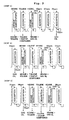
- FIGS. 2 and 3 show an example of the gas oil production apparatus based on the cyclic system.
- Each of Figs. 2 and 3 schematically shows a gas oil production apparatus based on the six tower-cyclic system which uses three towers of adsorptive desulfurization towers, one tower of substitution tower for the gas oil with hexane, one tower of desorption tower with toluene, and one tower of substitution tower for toluene with hexane respectively.
- the towers function, in the following order from the left in the drawing, as three towers of the adsorptive desulfurization towers, the substitution tower for toluene with hexane, the desorption tower with toluene, and the substitution tower for gas oil with hexane.
- the most downstream adsorptive desulfurization tower (3rd tower from the left) is connected to the right-adjoining tower immediately after the regeneration of the adsorptive desulfurization agent has been performed in the right-adjoining tower, i.e., the substitution tower for toluene with hexane (4th tower from the left) as shown in (Step 2) in Fig. 2. That is, at the stage of (Step 2), the substitution tower for toluene with hexane (4th tower from the left) is changed to the most downstream adsorptive desulfurization tower.
- the most upstream adsorptive desulfurization tower (1st tower from the left) is switched to the substitution tower for the gas oil with hexane.
- the gas oil which remains in the tower, is extruded and substituted with hexane.
- the most downstream adsorptive desulfurization tower is connected to the right-adjoining tower immediately after the regeneration of the adsorptive desulfurization agent has been performed in the right-adjoining tower.
- the most upstream adsorptive desulfurization tower is washed with hexane. That is, in the case of gas oil production apparatus based on the six tower-cyclic system shown in Figs. 2 and 3, as shown in (Step 1) to (Step 6) in Figs. 2 and 3, every time when the sulfur concentration of the product gas oil outflowed from the most downstream adsorptive desulfurization tower exceeds the predetermined concentration, the step carried out in the tower (adsorption ⁇ adsorption ⁇ adsorption ⁇ hexane substitution ⁇ desorption ⁇ hexane substitution ⁇ ) is shifted from the left to the right in the drawing one by one.
- the adsorptive desulfurization agent in order to remove a minute amount of adsorbed water as the pretreatment for the adsorptive desulfurization agent, it is preferable that the adsorptive desulfurization agent is dried at about 100 to 200 °C in the case of an oxidizing atmosphere such as air. However, if the temperature exceeds 200 °C, then the reaction occurs with oxygen, and the weight of the adsorptive desulfurization agent is decreased, which is not preferred.
- the adsorptive desulfurization agent is dried at about 100 to 800 °C. If the heat treatment is performed at 400 to 800 °C, then organic matters and contained oxygen are removed, and the adsorption performance is improved, which is especially preferred.
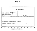
- the activated carbon fiber which is used as the carbon material for the adsorptive desulfurization agent, is capable of selectively adsorbing benzothiophene such as 4-methylbenzothiophene (4-MDBT) and 4,6-dimethylbenzothiophene (4,6-DMDBT) as compounds which are difficult to be desulfurized, of the sulfur compounds contained in the gas oil. Therefore, the composition distribution of the sulfur compounds remaining in the gas oil desulfurized by the method for producing the gas oil of the present invention is different from the composition distribution of the sulfur compounds remaining in the gas oil desulfurized by the conventional hydrotreating process.
- the remaining ratio of 4,6-DMDBT which is difficult to be desulfurized by the hydrotreating process is extremely lowered by the desulfurization method of the present invention. That is, the gas oil, which is obtained in accordance with the present invention, achieves the sulfur concentration of not more than 15 ppm. Further, the 90 % distillation temperature is scarcely changed before and after the desulfurization. It is appreciated that the desulfurization method of the present invention does not exert any harmful influence on the quality of the gas oil.
- the desulfurization method of the present invention When the desulfurization method of the present invention is combined with the conventional hydrotreating, it is possible to reduce the sulfur content more efficiently. Almost all of the sulfur compounds remaining in the gas oil desulfurized by the hydrotreating are alkylbenzothiophene which is the compound difficult to be desulfurized. Therefore, when the gas oil, which has been desulfurized to give a sulfur concentration of not more than 10 ppm by the hydrotreating, is further desulfurized in accordance with the desulfurization method of the present invention, it is possible to selectively adsorb and remove alkylbenzothiophene. Therefore, it is possible to efficiently obtain the gas oil having a sulfur concentration of not more than 1 ppm.
- the nitrogen compounds are removed from the gas oil distillate products. Therefore, the desulfurization effect, which is brought about by the adsorptive desulfurization agent, is further improved.
- the activated carbon, especially the activated carbon fiber, which is used for the adsorptive desulfurization agent of the present invention has such a property that polycyclic aromatic compounds, especially aromatic compounds having two or more rings are selectively adsorbed. Therefore, the ratio of polycyclic aromatic compounds remaining in the gas oil refined by the desulfurizing method of the present invention is lower than the ratio of polycyclic aromatic compounds remaining in the gas oil desulfurized and refined by the conventional hydrotreating. That is, as for the gas oil obtained by the present invention, it is achieved that the sulfur concentration is not more than 15 ppm, and the ratio of aromatic compounds having two or more rings is not more than 7 % with respect to the total aromatic content. It is achieved that the ratio of aromatic compounds having three rings with respect to the total aromatic content is less than 0.5 %. Therefore, it is appreciated that the gas oil, which is desirable in view of the environment, is obtained when the desulfurization method of the present invention is used.
- the adsorption-desulfurized gas oil obtained by the production method of the present invention is mixed with any synthetic gas oil such as GTL (gas to liquid), it is possible to efficiently produce the gas oil in which the sulfur content is extremely small, and the polycyclic aromatic compound content is extremely small.
- GTL gas to liquid
- the sulfur content is removed to be not more than 1 ppm, it is also possible to reduce the sulfur poisoning of the noble metal catalyst for hydrogenizing the benzene ring, i.e., so-called the nuclear hydrogenation catalyst.
- Example 1 those prepared as the adsorptive desulfurization agents (hereinafter referred to as "adsorbents”) respectively were activated carbon fiber A having a specific surface area of about 2,000 m 2 /g, activated carbon fiber B having a specific surface area of about 1,000 m 2 /g, and powder activated carbon Darco KB produced by Aldrich having a specific surface area of 1,500 m 2 /g. The adsorption characteristics of the respective adsorbents were measured.
- adsorbents were dried at 150 °C for 3 hours in a pretreatment for the respective adsorbent prepared in Example 1.
- adsorbents of NaY type zeolite powder HSZ-320 NAA produced by Tosoh Corporation (SiO 2 /Al 2 O, ratio: 5.5 mol/mol, Na 2 O/Al 2 O 3 ratio: 1.01 mol/mol, specific surface area: 700 m 2 /g, crystallite diameter: 0.2 to 0.4 ⁇ m, particle diameter: 7 to 10 ⁇ m)
- HY type zeolite powder HSZ-320 HOA produced by Tosoh Corporation (SiO 2 /Al 2 O, ratio: 5.7 mol/mol, Na 2 O: 3.8 % by weight, specific surface area: 550 m 2 /g, crystallite diameter: 0.2 to 0.4 ⁇ m, particle diameter: 6 to 10 ⁇ m)
- an adsorbent in which NH 4 ⁇ -zeolite powder HSZ-930 NHA produced by Tosoh Corporation (SiO 2 /Al 2 O 3 ratio: 27 mol/mol, Na: 0.02 % by weight, specific surface area after calcination: 630 m 2 /g, crystallite diameter: 0.02 to 0.04 ⁇ m, particle diameter: 3 to 6 ⁇ m) was calcined at 650°C for 3 hours to obtain the proton type, was also prepared.
- the adsorption capacity of DBT was measured for the various adsorbents prepared in this embodiment by using a toluene solution containing dibenzothiophene (DBT) by 10 % by weight as a sample assuming the gas oil distillate products.
- DBT dibenzothiophene
- DBT produced by Tokyo Kasei Kogyo Co., Ltd., special grade dibenzothiophene
- 1.0 g of each of the adsorbents was immersed at room temperature for not less than 24 hours in 4.0 g of 10 % by weight DBT/toluene solution to measure the contents of the sulfur compounds before and after the immersion by the gas chromatography.
- the adsorption capacity was measured.
- the adsorption capacity of the activated carbon fiber B having the specific surface area of about 1,000 m 2 /g is larger than that of the powder activated carbon Darco KB having the specific surface area of 1,500 m 2 /g. It has been revealed that the adsorptive desulfurization performance of the activated carbon fiber is more excellent than that of the powder activated carbon.
- Type of adsorbent Adsorption capacity (g-S/kg-adsorbent) Activated carbon fiber A 52 Activated carbon fiber B 46 Powder activated carbon Darco KB 25 Zeolite HSZ-320 NAA 0 Zeolite HSZ-320 HOA 6 Zeolite HSZ-331 HSA 11 Zeolite HSZ-330 HUA 8 Zeolite HSZ-500 KOA -2 Zeolite HSZ-640 HOA 0 Zeolite HSZ-642 NAA -1 Zeolite HSZ-720 KOA -1 Zeolite F-9 16 Silica gel WAKOGEL-G 1 Activated alumina F-200 3 Copper-carrying alumina NK-311 -1 Zeolite HSZ-930 NHA 4
- Activated carbon fiber A, activated carbon fiber B, zeolite HSZ-320 NAA, zeolite HSZ-331 HSA, zeolite F-9, and zeolite HSZ-930 NHA which were included in the various adsorbents prepared for the adsorptive desulfurization performance 1, were evaluated for the adsorptive desulfurization performance by using actual gas oil. 3.0 g of each of the adsorbents was immersed at room temperature for not less than 24 hours in 20.0 g of super deep desulfurization gas oil A (sulfur content: 37 ppm) and super deep desulfurization gas oil B (sulfur content: 30 ppm) with sulfur concentrations having been previously measured respectively to measure sulfur concentrations after the immersion.
- super deep desulfurization gas oil A sulfur content: 37 ppm
- super deep desulfurization gas oil B sulfur content: 30 ppm
- Type of adsorbent Sulfur content of super deep desulfurization gas oil A (ppm) Sulfur content of super deep desulfurization gas oil B (ppm) Activated carbon fiber A 2 2 Activated carbon fiber B 9 8 Zeolite HSZ-320 NAA 31 28 Zeolite HSZ-331 HSA 27 23 Zeolite F-9 33 26 Zeolite HSZ-930 NHA 24 21
- Activated carbon fiber A, zeolite HSZ-320 NAA, zeolite HSZ-331 HSA, zeolite F-9, and zeolite HSZ-930 NHA which were included in the various adsorbents prepared for the adsorptive desulfurization performance 1, were evaluated for the adsorptive desulfurization performance by using gasoline base.
- 6.0 g of each of the adsorbents was immersed at room temperature for not less than 24 hours in 40.0 g of catalytic cracking (FCC) gasoline (sulfur content: 62 ppm) with a sulfur concentration having been previously measured to measure a sulfur concentration in the FCC gasoline after the immersion. Obtained results are shown in Table 3.
- FCC catalytic cracking
- the activated carbon fiber A has more excellent adsorptive desulfurization performance as compared with zeolite.
- Type of adsorbent Sulfur content of FCC gasoline (ppm) Activated carbon fiber A 25 Zeolite HSZ-320 NAA 47 Zeolite HSZ-331 HSA 38 Zeolite F-9 33 Zeolite HSZ-930 NHA 49
- the activated carbon fiber A was used as the adsorbent for the experiment for the adsorptive desulfurization performance 1 described above. After that, the temperature was raised for the activated carbon fiber A to 500 °C at a temperature-raising speed of 100 °C/hr in a nitrogen atmosphere, and then the activated carbon fiber was heated at 500 °C for 2 hours. After the cooling, an experiment was performed in the same manner as for the adsorptive desulfurization performance 1. As a result, the adsorption capacity was 84 (g-S/kg-adsorbent). The regeneration of the adsorbent was confirmed.
- Example 2 the following thirteen adsorbents A to M were prepared to determine adsorption capacities with respect to the sulfur contents in the gas oil by using the adsorbents respectively.
- the following parameters are used for the adsorbents A to N as described later on.
- Sext represents the micropore external specific surface area (m 2 /g)
- Vext represents the micropore external pore volume (cm 3 /g)
- Smicro represents the micropore specific surface area (m 2 /g)
- Vmicro represents the micropore volume (cm 3 /g)
- D represents the density conversion coefficient (0.001547 when nitrogen is used as the gas) (cm 3 liq/cm 3 (STP))
- Sa represents the total specific surface area (m 2 /g)
- Va represents the total pore volume (cm 3 /g)
- Da represents the average pore diameter.
- the respective parameters were determined by using the results of the measurement based on the nitrogen adsorption method and the expressions (2) to (8) described above.
- Powdery activated carbon fiber was used as the adsorbent A.
- Sa was 2,669 m 2 /g
- Va was 1.36 cm 3 /g
- Da was 20 angstroms
- Smicro was 2,630 m 2 /g
- Vmicro was 1.29 cm 3 /g
- Sext was 40 m 2 /g
- Vext was 0.07 cm 3 /g
- Smicro x 2 x Vext/Sext was 9.2 cm 3 /g.
- Powdery activated carbon fiber was used as the adsorbent B.
- Sa was 1,155 m 2 /g
- Va was 0.44 cm 3 /g
- Da was 15 angstroms
- Smicro was 1,137 m 2 /g
- Vmicro was 0.40 cm 3 /g
- Sext was 18 m 2 /g
- Vext was 0.03 cm 3 /g
- Smicro x 2 x Vext/Sext was 4.3 cm 3 /g.
- Powdery activated carbon fiber was used as the adsorbent C.
- Sa was 2,090 m 2 /g
- Va was 1.04 cm 3 /g
- Da was 20 angstroms
- Smicro was 2,071 m 2 /g
- Vmicro was 1.01 cm 3 /g
- Sext was 19 m 2 /g
- Vext was 0.03 cm 3 /g
- Smicro x 2 x Vext/Sext was 9.2 cm 3 /g.
- the adsorbent C was used in the fibrous state as it was.
- Activated carbon fiber (W-15W produced by Unitica Ltd.) was used as the adsorbent D.
- Sa was 1,390 m 2 /g
- Va was 1.30 cm 3 /g
- Da was 37 angstroms
- Smicro was 1,369 m 2 /g
- Vmicro was 1.26 cm 3 /g
- Sext was 21 m 2 /g
- Vext was 0.04 cm 3 /g
- Smicro x 2 x Vext/Sext was 4.6 cm 3 /g.
- the adsorbent D was used in the fibrous state as it was.
- Activated carbon fiber (FR-15 produced by Kuraray Chemical Co., Ltd.) was used as the adsorbent E.
- Sa was 1,515 m 2 /g
- Va was 0.54 cm 3 /g
- Da was 14 angstroms
- Smicro was 1,513 m 2 /g
- Vmicro was 0.54 cm 3 /g
- Sext was 1 m 2 /g
- Vext was 0.0012 cm 3 /g
- Smicro x 2 x Vext/Sext was 3.7 cm 3 /g.
- the adsorbent E was used in the fibrous state as it was.
- Activated carbon fiber (FR-20 produced by Kuraray Chemical Co., Ltd.) was used as the adsorbent F.
- Sa was 2,454 m 2 /g
- Va was 0.86 cm 3 /g
- Da was 14 angstroms
- Smicro was 2,445 m 2 /g
- Vmicro was 0.85 cm 3 /g
- Sext was 8 m 2 /g
- Vext was 0.01 cm 3 /g
- Smicro x 2 x Vext/Sext was 7.4 cm 3 /g.
- the adsorbent F was used in the fibrous state as it was.
- Activated carbon fiber (FR-20 produced by Kuraray Chemical Co., Ltd.) was used as the adsorbent G.
- Sa was 2,294 m 2 /g
- Va was 0.81 cm 3 /g
- Da was 14 angstroms
- Smicro was 2,285 m 2 /g
- Vmicro was 0.80 cm 3 /g
- Sext was 9 m 2 /g
- Vext was 0.01 cm 3 /g
- Smicro x 2 x Vext/Sext was 7.0 cm 3 /g.
- the adsorbent G was used in the fibrous state as it was.
- Activated carbon fiber (FR-25 produced by Kuraray Chemical Co., Ltd.) was used as the adsorbent H.
- Sa was 2,749 m 2 /g
- Va was 0.96 cm 3 /g
- Da was 14 angstroms
- Smicro was 2,741 m 2 /g
- Vmicro was 0.94 cm 3 /g
- Sext was 8 m 2 /g
- Vext was 0.01 cm 3 /g
- Smicro x 2 x Vext/Sext was 8.8 cm 3 /g.
- the adsorbent H was used in the fibrous state as it was.
- Activated carbon fiber (FE-620-7 produced by Toho Rayon Co., Ltd.) was used as the adsorbent I.
- Sa was 1,916 m 2 /g
- Va was 0.66 cm 3 /g
- Da was 14 angstroms
- Smicro was 1,913 m 2 /g
- Vmicro was 0.66 cm 3 /g
- Sext was 3 m 2 /g
- Vext was 0.01 cm 3 /g
- Smicro x 2 x Vext/Sext was 6.6 cm 3 /g.
- the adsorbent I was used in the fibrous state as it was.
- Activated carbon fiber in felt form (FT-300-20 produced by Kuraray Chemical Co., Ltd.) was used as the adsorbent J.
- Sa was 2,119 m 2 /g
- Va was 0.75 cm 3 /g
- Da was 14 angstroms
- Smicro was 2,115 m 2 /g
- Vmicro was 0.75 cm 3 /g
- Sext was 3 m 2 /g
- Vext was 0.01 cm 3 /g
- Smicro x 2 x Vext/Sext was 7.6 cm 3 /g.
- Powdery activated carbon was used as the adsorbent K.
- Sa was 996 m 2 /g
- Va was 0.35 cm 3 /g
- Da was 14 angstroms
- Smicro was 989 m 2 /g
- Vmicro was 0.34 cm 3 /g
- Sext was 7 m 2 /g
- Vext was 0.01 cm 3 /g
- Smicro x 2 x Vext/Sext was 3.3 cm 3 /g.
- Powdery activated carbon (Max Soap produced by Kansai Coke and Chemicals Co., Ltd.) was used as the adsorbent L.
- Sa was 3,305 m 2 /g
- Va was 1.67 cm 3 /g
- Da was 20 angstroms
- Smicro was 3,264 m 2 /g
- Vmicro was 1.60 cm 3 /g
- Sext was 42 m 2 /g
- Vext was 0.07 cm 3 /g
- Smicro x 2 x Vext/Sext was 11.3 cm 3 /g.
- Powdery activated carbon was used as the adsorbent M.
- Sa was 2,264 m 2 /g
- Va was 0.80 cm 3 /g
- Da was 14 angstroms
- Smicro was 2,260 m 2 /g
- Vmicro was 0.79 cm 3 /g
- Sext was 4 m 2 /g
- Vext was 0.01 cm 3 /g
- Smicro x 2 x Vext/Sext was 7.7 cm 3 /g.
- Activated carbon fiber (FR-10 produced by Kuraray Chemical Co., Ltd.) was used as the adsorbent N.
- Sa was 1,101 m 2 /g
- Va was 0.39 cm 3 /g
- Da was 14 angstroms
- Smicro was 1,090 m 2 /g
- Vmicro was 0.39 cm 3 /g
- Sext was 11 m 2 /g
- Vext was 0.00 cm 3 /g
- Smicro x 2 x Vext/Sext was 0.0 cm 3 /g.
- the adsorbent N was used in the fibrous state as it was.
- the adsorbents A to N were dried at 150 °C for 3 hours. After that, 1.0 g of each of the adsorbents was immersed at 10 °C for not less than 24 hours in 20.0 g of gas oil (sulfur concentration: 370 ppm, density: 0.8421 g/ml (15 °C), nitrogen content (weight after conversion into weight of nitrogen in nitrogen compounds): 10 ppm, boiling point range: 193.5 to 361.5 °C, 10 % distillation temperature: 270.0 °C, 90 % distillation temperature: 343.5 °C) to determine the adsorption capacity by measuring the sulfur concentration after the immersion.
- gas oil sulfur concentration: 370 ppm, density: 0.8421 g/ml (15 °C)
- nitrogen content weight after conversion into weight of nitrogen in nitrogen compounds
- Fig. 4 shows the relationship between Smicro x 2 x Vext/Sext and the adsorption capacity. As clarified from Fig. 4, it has been revealed that as Smicro x 2 x Vext/Sext is larger, the adsorption capacity becomes larger. According to this result, it is appreciated that Smicro x 2 x Vext/Sext, which is the desulfurization adsorption parameter found out by the inventors, determines the adsorption amount of the sulfur content.
- the adsorption capacity is not less than 2.0 g-S/kg-dry adsorbent.
- the adsorption capacity exceeds 2.5 g-S/kg-dry adsorbent. It has been revealed that the adsorbent, which has the excellent adsorptive desulfurization performance, can be obtained.
- Example 3 the adsorbent H prepared in Example 2 was used as the adsorbent. At first, the adsorbent was dried at 150 °C for 3 hours, and then 19.6 g of the adsorbent was charged into an adsorption tower (hereinafter referred to as "column") having a length of 600 mm and an internal volume of 54 ml.
- column an adsorption tower
- gas oil (sulfur concentration: 38 ppm, density: 0.8377 g/ml (15 °C), nitrogen content: 0.6 ppm, boiling point range: 206.0 to 367.0 °C, 10 % distillation temperature: 271.0 °C, 90 % distillation temperature: 347.5 °C) was allowed to flow through the column at 2 ml/min. After that, the sulfur content contained in the gas oil and the concentration of the gas oil with respect to the accumulated outflow amount of the gas oil outflowed from the column were measured. The change is shown in Fig. 5. The sulfur content was measured by the fluorescent X-ray analysis. However, the left vertical axis in Fig.
- the accumulated outflow amount along with the horizontal axis in Fig. 5 means the ratio of the outflow amount of the outflow liquid from the column to the volume of the adsorbent.
- the initial concentration of the sulfur content was 5 ppm which was low. It is appreciated that the sulfur content is sufficiently adsorbed by the adsorbent.
- the adsorption amount was determined from Fig. 5. As a result, the adsorption amount was 26 mg.
- the adsorption amount was determined by integrating the amount of the decrease in the sulfur content of the gas oil outflowed from the column with respect to the sulfur content of the gas disallowed to flow through the column according to Fig. 5.
- a distillate product which was obtained by pooling the outflow liquid until an accumulated outflow liquid amount of 3.3 ml/ml-adsorbents, was regarded as the adsorption-desulfurized gas oil.
- n-decane was allowed to flow through the column at 2 ml/min.
- concentration of the gas oil with respect to the accumulated outflow amount of the mixture liquid outflowed from the column the concentration of n-decane, and the sulfur content contained in the mixture liquid were measured.
- the change is shown in Fig. 6.
- the left vertical axis in Fig. 6 indicates the concentrations of the gas oil and n-decane
- the right vertical axis indicates the concentration of the sulfur content.
- the outflow amount of the gas oil was decreased, and the concentration was finally decreased to approximately zero.
- toluene (desorbent), which was heated to 100 °C, was allowed to flow through the column at 2 ml/min.
- concentration of the desorbent with respect to the accumulated outflow amount of the mixture liquid outflowed from the column the concentration of n-decane, and the sulfur content contained in the mixture liquid were measured.
- the change is shown in Fig. 7.
- the left vertical axis in Fig. 7 indicates the concentrations of the desorbent and n-decane
- the right vertical axis indicates the concentration of the sulfur content.
- the outflow amount of the sulfur content is initially increased.
- n-decane was allowed to flow again through the column at 2 ml/min, and then the gas oil was allowed to flow through the column at 2 ml/min.
- concentration of the gas oil with respect to the accumulated outflow amount of the mixture liquid outflowed from the column, the concentration of n-decane, and the sulfur content contained in the mixture liquid were measured.
- the change is shown in Fig. 8.
- Fig. 8 also shows the change of the sulfur content upon the first flow of the gas oil.
- the left vertical axis in Fig. 8 indicates the concentrations of the gas oil and n-decane
- the right vertical axis indicates the concentration of the sulfur content.
- Table 4 summarizes the properties and the compositions of the feed gas oil used in this embodiment and the adsorption-desulfurized gas oil produced in this embodiment. For the purpose of comparison, Table 4 also shows the properties and the compositions of the hydrotreated gas oil.
- Feed gas oil Adsorption-desulfurized gas oil (first) Adsorption-desulfurized gas oil (second) Hydrorefined gas oil Sulfur content (wt ppm) 38 12 11 8 Sulfur content of 4-MDBT (wt ppm) 0.8 0.2 - 0.4 Sulfur content of 4,6-DMDBT (wt ppm) 7 0.3 - 2 Ratio of 4,6-DMDBT to total sulfur content (%) 18 3 - 20 Total aromatic content (wt %) 17.5 15.5 14.4 14.0 Aromatic compounds with 1 ring (wt %) 16.0 14.9 13.9 12.9 Aromatic compounds with 2 rings (wt %) 1.20 0.49 0.40 0.92 Aromatic compounds with 2.5 rings (wt %) 0.18 0.06 0.03 0.11 Aroma
- the aromatic content, especially the aromatic content of aromatic compounds having two or more rings is reduced as compared with the hydrotreated oil.
- the ratios of the aromatic contents of aromatic compounds having not less than two rings and aromatic compounds having not less than three rings with respect to the total aromatic content are remarkably lowered, although the weight of the total aromatic content is not lowered so much as compared with the feed gas oil. It is appreciated that the color of the gas oil is remarkably improved as compared with the hydrotreated gas oil (not less than +30). Further, the ratio of the sulfur compound of 4,6-DMDBT to the total sulfur content is 3 % which is an extremely low value.
- the adsorbent used in this embodiment can selectively adsorb 4,6-DMDBT.
- the 90 % distillation point is compared such that the 90 % distillation point of the feed gas oil is 347.5 °C, while the 90 % distillation point of the gas oil after the adsorptive desulfurization is 347.0 °C which is approximately the same value as that of the feed gas oil. That is, it has been revealed that the method for producing the gas oil based on the adsorptive desulfurization used in this embodiment makes it possible to produce the gas oil without changing the characteristics of the gas oil itself while reducing the sulfur content contained in the gas oil.
- Example 4 the adsorbent J prepared in Example 2 was used as the adsorbent.
- the adsorbent was dried at 150 °C for 3 hours in the pretreatment, and then 17.3 g in total of the adsorbent was charged to two columns each having a length of 600 mm and an internal volume of 54 ml.
- Gas oil sulfur concentration: 38 ppm, density: 0.8377 g/ml (15 °C), nitrogen content: 0.6 ppm, boiling point range: 206.0 to 367.0 °C, 10 % distillation temperature: 271.0 °C, 90 % distillation temperature: 347.5 °C
- the temperature of the columns was raised by the heating from room temperature to 160 °C.
- the nitrogen gas was supplied to the columns at a pressure of 1.5 kgf/cm 2 G (0.15 MPa G) at a flow rate of 3 ml/min to extrude and recover the gas oil from the columns in accordance with the pressure of the nitrogen gas.
- the recovery amount of the gas oil was 70 ml.
- toluene was allowed to flow through the columns at 2 ml/min. According to the concentration of the gas oil contained in toluene outflowed from the columns, it was revealed that the amount of the gas oil remaining in the columns was 11 ml. Subsequently, the temperature of the columns was raised by the heating from room temperature to 160 °C. The nitrogen gas was supplied to the columns at a pressure of 1.5 kgf/cm 2 G (0.15 MPa G) at a flow rate of 3 ml/min to extrude and recover toluene from the columns in accordance with the pressure of the nitrogen gas. The recovery amount of toluene was 74 ml.
- the gas oil was allowed to flow through the columns again. According to the concentration of toluene contained in the gas oil outflowed from the columns, it was revealed that the amount of toluene remaining in the columns was 10 ml. As described above, it has been confirmed that about 90 % of the liquid in the columns can be recovered by using the pressure of the nitrogen gas.
- the adsorptive desulfurization performance with gasoline base was evaluated for zeolite HSZ-320 NAA, zeolite F-9, activated carbon fiber H, a mixture obtained by mixing zeolite HSZ-320 NAA and activated carbon fiber H at a ratio of 50 mass %: 50 mass %, and a mixture obtained by mixing zeolite F-9 and activated carbon fiber H at a ratio of 50 mass %: 50 mass %.
- the sulfur concentrations after the immersion are shown in Tables 5 and 6.
- the sulfur concentration is lowered in the case of 50 mass % zeolite F-9 + 50 mass % activated carbon fiber H as compared with the case of 100 mass % zeolite F-9 and that the sulfur concentration is lowered in the case of 50 mass % zeolite HSZ-320 NAA + 50 mass % activated carbon fiber H as compared with the case of 100 mass % zeolite HSZ-320 NAA. It is possible to confirm the effectiveness of the combination with the activated carbon fiber.
- Type of adsorbent Sulfur content of FCC gasoline (relative value) 100 mass % zeolite HSZ-320 NAA 100 100 mass % activated carbon fiber H 60 50 mass % zeolite HSZ-320 NAA + 50 mass % activated carbon fiber H 66
- Type of adsorbent Sulfur content of FCC gasoline (relative value) 100 mass % zeolite F-9 100 100 mass % activated carbon fiber H 100 50 mass % zeolite F-9 + 50 mass % activated carbon fiber H 89
- the adsorbent can be subjected to the desorption regeneration to use the adsorbent again for the adsorptive desulfurization after the sulfur content contained in the gas oil is adsorbed and desulfurized. Therefore, the sulfur content can be sufficiently removed for a long period of time at relatively low equipment cost and running cost.
- the sulfur compounds and the polycyclic aromatic compounds can be selectively removed by using the carbon material, especially the activated carbon fiber for the adsorptive desulfurization agent. Therefore, it is possible to provide the gas oil which is more environment-friendly. Further, according to the method for producing the gas oil of the present invention, DBT compounds, especially 4,6-DMDBT, which are difficult to be desulfurized by the hydrotreating, can be selectively reduced as well. Therefore, when the desulfurization method of the present invention is combined with the hydrotreating, it is possible to refine the gas oil to give a sulfur concentration of not more than 10 ppm and especially a sulfur concentration of not more than 1 ppm.
- the adsorption-desulfurized gas oil which is obtained by the method for producing the gas oil of the present invention, has the 90 % distillation point of the value which is approximately the same as that of the feed gas oil. Therefore, according to the method for producing the gas oil of the present invention, it is possible to produce the gas oil without changing the characteristics of the gas oil itself while reducing the sulfur content contained in the gas oil.
Landscapes
- Chemical & Material Sciences (AREA)
- Analytical Chemistry (AREA)
- Organic Chemistry (AREA)
- Chemical Kinetics & Catalysis (AREA)
- Inorganic Chemistry (AREA)
- Engineering & Computer Science (AREA)
- Oil, Petroleum & Natural Gas (AREA)
- Materials Engineering (AREA)
- Physics & Mathematics (AREA)
- Thermal Sciences (AREA)
- General Chemical & Material Sciences (AREA)
- Solid-Sorbent Or Filter-Aiding Compositions (AREA)
- Production Of Liquid Hydrocarbon Mixture For Refining Petroleum (AREA)
Applications Claiming Priority (5)
| Application Number | Priority Date | Filing Date | Title |
|---|---|---|---|
| JP2002147618 | 2002-05-22 | ||
| JP2002147618 | 2002-05-22 | ||
| JP2003044257 | 2003-02-21 | ||
| JP2003044257 | 2003-02-21 | ||
| PCT/JP2003/006336 WO2003097771A1 (en) | 2002-05-22 | 2003-05-21 | Adsorption desulfurization agent for desulfurizing petroleum fraction and desulfurization method using the same |
Publications (2)
| Publication Number | Publication Date |
|---|---|
| EP1514917A1 true EP1514917A1 (de) | 2005-03-16 |
| EP1514917A4 EP1514917A4 (de) | 2007-05-23 |
Family
ID=29552343
Family Applications (1)
| Application Number | Title | Priority Date | Filing Date |
|---|---|---|---|
| EP03733022A Withdrawn EP1514917A4 (de) | 2002-05-22 | 2003-05-21 | Adsorptionsentschwefelungsmittel zur entschwefelung einer erdölfraktion und entschwefelungsverfahren, bei dem dieses zur anwendung kommt |
Country Status (6)
| Country | Link |
|---|---|
| US (1) | US20050173297A1 (de) |
| EP (1) | EP1514917A4 (de) |
| JP (2) | JP4336308B2 (de) |
| AU (1) | AU2003242363A1 (de) |
| CA (1) | CA2486886A1 (de) |
| WO (1) | WO2003097771A1 (de) |
Cited By (8)
| Publication number | Priority date | Publication date | Assignee | Title |
|---|---|---|---|---|
| WO2006136862A1 (en) * | 2005-06-20 | 2006-12-28 | Johnson Matthey Plc | Removal of nitrogen compounds |
| WO2006105456A3 (en) * | 2005-03-30 | 2007-03-08 | Bp Corp North America Inc | Process for removing color bodies from hydrocarbon-based fuels using actived carbon |
| US7550074B2 (en) | 2001-03-29 | 2009-06-23 | Bp Oil International Limited | Process for treating fuel |
| EP1923451A4 (de) * | 2005-08-01 | 2013-03-06 | Japan Energy Corp | Verfahren zur entschwefelung von kohlenwasserstofföl |
| CN104645951A (zh) * | 2013-11-21 | 2015-05-27 | 东营科尔特化工科技有限公司 | 一种液化石油气精脱硫剂的再生方法 |
| CN105219424A (zh) * | 2015-11-03 | 2016-01-06 | 四川省盖亚环保科技有限公司 | 吸附脱硫装置及吸附脱硫方法 |
| CN106590728A (zh) * | 2016-12-15 | 2017-04-26 | 浙江工业大学 | 一种以Cu2O/SiO2‑Al2O3复合气凝胶为吸附剂脱除燃料油中噻吩类硫的方法 |
| CN109331840A (zh) * | 2018-10-24 | 2019-02-15 | 南京工业大学 | 一种酸碱协同碳基催化剂的制备方法及其应用 |
Families Citing this family (49)
| Publication number | Priority date | Publication date | Assignee | Title |
|---|---|---|---|---|
| CA2553713C (en) * | 2004-02-02 | 2013-05-28 | Japan Energy Corporation | Method of desulfurizing hydrocarbon oil |
| FR2878252B1 (fr) * | 2004-11-23 | 2008-08-22 | Inst Francais Du Petrole | Procede de desulfuration d'une coupe hydrocarbonee en lit mobile simule |
| DE102005001793A1 (de) * | 2005-01-13 | 2006-07-27 | Basf Ag | Polyoxymethylen und Zeolith enthaltende Formmasse |
| JP2006348091A (ja) * | 2005-06-14 | 2006-12-28 | National Institute Of Advanced Industrial & Technology | 軽質燃料油中の含硫黄化合物の分離、濃縮方法 |
| JP2009525180A (ja) * | 2006-01-30 | 2009-07-09 | アドバンスド テクノロジー マテリアルズ,インコーポレイテッド | 流体貯留/分配、脱硫、および赤外線放射に有用な炭素材料、ならびにそれを使用する装置および方法 |
| KR101264330B1 (ko) * | 2006-02-18 | 2013-05-14 | 삼성에스디아이 주식회사 | 연료전지용 연료가스의 탈황 장치 및 이를 이용한 탈황방법 |
| JP4854076B2 (ja) * | 2006-06-28 | 2012-01-11 | Jx日鉱日石エネルギー株式会社 | 超低硫黄軽油基材の製造方法及び超低硫黄軽油組成物 |
| US8319145B2 (en) | 2006-07-10 | 2012-11-27 | Lazare Kaplan International, Inc. | System and method for gemstone micro-inscription |
| US7776785B2 (en) * | 2006-10-13 | 2010-08-17 | Idemitsu Kosan Co., Ltd. | Catalyst for carbon monoxide conversion and method of carbon monoxide modification with the same |
| US8246814B2 (en) * | 2006-10-20 | 2012-08-21 | Saudi Arabian Oil Company | Process for upgrading hydrocarbon feedstocks using solid adsorbent and membrane separation of treated product stream |
| US9315733B2 (en) * | 2006-10-20 | 2016-04-19 | Saudi Arabian Oil Company | Asphalt production from solvent deasphalting bottoms |
| US7842181B2 (en) * | 2006-12-06 | 2010-11-30 | Saudi Arabian Oil Company | Composition and process for the removal of sulfur from middle distillate fuels |
| JP5392993B2 (ja) * | 2007-04-06 | 2014-01-22 | Jx日鉱日石エネルギー株式会社 | 超低硫黄軽油基材の製造方法 |
| CA2698366A1 (en) | 2007-09-07 | 2009-03-12 | Japan Energy Corporation | Solid acid, method for preparing the solid acid, and method for desulfurizing hydrocarbon oil using the solid acid as desulfurizing agent |
| US8142646B2 (en) * | 2007-11-30 | 2012-03-27 | Saudi Arabian Oil Company | Process to produce low sulfur catalytically cracked gasoline without saturation of olefinic compounds |
| US20090145808A1 (en) * | 2007-11-30 | 2009-06-11 | Saudi Arabian Oil Company | Catalyst to attain low sulfur diesel |
| US9636662B2 (en) | 2008-02-21 | 2017-05-02 | Saudi Arabian Oil Company | Catalyst to attain low sulfur gasoline |
| US8142647B2 (en) * | 2008-12-16 | 2012-03-27 | Chevron U.S.A. Inc. | Adsorption of dibenzothiophenes from hydrocarbon and model diesel feeds |
| JP2012512735A (ja) * | 2008-12-18 | 2012-06-07 | シエル・インターナシヨナル・リサーチ・マートスハツペイ・ベー・ヴエー | 酸化し、炭酸アンモニウム、水酸化アンモニウムおよび水の混合物を用いて処理することによるフィッシャー・トロプシュ触媒の再生 |
| US9005432B2 (en) | 2010-06-29 | 2015-04-14 | Saudi Arabian Oil Company | Removal of sulfur compounds from petroleum stream |
| CA2813907C (en) | 2010-10-08 | 2018-05-15 | Siemens Industry, Inc. | Mesoporous activated carbon and methods of producing same |
| CN103476489B (zh) * | 2011-01-07 | 2016-08-10 | 阿克伦大学 | 低成本的固定化胺可再生固体吸附剂 |
| US8535518B2 (en) | 2011-01-19 | 2013-09-17 | Saudi Arabian Oil Company | Petroleum upgrading and desulfurizing process |
| US8679231B2 (en) | 2011-01-19 | 2014-03-25 | Advanced Technology Materials, Inc. | PVDF pyrolyzate adsorbent and gas storage and dispensing system utilizing same |
| MX362027B (es) | 2011-10-07 | 2019-01-04 | Teijin Pharma Ltd | Adsorbentes para la administración oral. |
| WO2014002115A2 (en) * | 2012-06-27 | 2014-01-03 | Reliance Industries Limited | A system and a method for measurement of adsorption isotherms and kinetics of hydrocarbons |
| KR101394343B1 (ko) * | 2012-07-05 | 2014-05-13 | 경북대학교 산학협력단 | 유기황 흡착제, 이의 제조방법, 액상 석유유분에서의 유기황 화합물 흡착방법 및 유기황 흡착제의 재생방법 |
| CA2902867C (en) | 2013-03-15 | 2021-06-29 | Evoqua Water Technologies Llc | Mesoporous activated carbon |
| KR101565852B1 (ko) * | 2013-07-18 | 2015-11-05 | 에쓰대시오일 주식회사 | 희토류 및 전이금속이 담지된 유기황 흡착제, 이의 제조방법, 액상 석유유분에서의 유기황 화합물 흡착방법 및 유기황 흡착제의 재생방법 |
| US20150225245A1 (en) * | 2014-02-11 | 2015-08-13 | Corning Incorporated | Method for forming activated carbon |
| US10011779B2 (en) * | 2015-02-04 | 2018-07-03 | China University Of Petroleum-Beijing | Adsorbent for desulfurization of gasoline and method for desulfurization of gasoline |
| US9683183B2 (en) * | 2015-02-04 | 2017-06-20 | China University of Petroleum—Beijing | Method for deep desulfurization of gasoline |
| US10266778B2 (en) * | 2015-02-04 | 2019-04-23 | China University Of Petroleum-Beijing | Method for upgrading fluid catalytic cracking gasoline |
| JP6769597B2 (ja) * | 2015-06-09 | 2020-10-14 | ユニチカ株式会社 | 浄油器フィルター |
| JP6654286B2 (ja) * | 2015-12-28 | 2020-02-26 | 出光興産株式会社 | A重油組成物 |
| CN106378090A (zh) * | 2016-09-29 | 2017-02-08 | 国家电网公司 | 一种劣化的电厂备用柴油的处理方法 |
| US10752847B2 (en) | 2017-03-08 | 2020-08-25 | Saudi Arabian Oil Company | Integrated hydrothermal process to upgrade heavy oil |
| US10703999B2 (en) | 2017-03-14 | 2020-07-07 | Saudi Arabian Oil Company | Integrated supercritical water and steam cracking process |
| GB201711157D0 (en) | 2017-07-11 | 2017-08-23 | Univ Liverpool | Sulfur-Doped Carbonaceous porous materials |
| US10526552B1 (en) | 2018-10-12 | 2020-01-07 | Saudi Arabian Oil Company | Upgrading of heavy oil for steam cracking process |
| US10822549B2 (en) | 2019-01-18 | 2020-11-03 | Baker Hughes Holdings Llc | Methods and compounds for removing non-acidic contaminants from hydrocarbon streams |
| WO2020174610A1 (ja) * | 2019-02-27 | 2020-09-03 | 日揮グローバル株式会社 | 炭素系吸着材の再生方法及び炭素系吸着材の再生システム |
| JP7015622B2 (ja) * | 2019-03-12 | 2022-02-03 | 株式会社オメガ | 排水処理方法 |
| CN110923020B (zh) * | 2019-12-09 | 2025-04-08 | 沈阳环境科学研究院 | 一种分级回收焦油系统 |
| US20210214634A1 (en) * | 2020-01-12 | 2021-07-15 | Vijay Sukhdeo | Nano technology to reduce sulfur content |
| EP4148027B1 (de) | 2020-05-08 | 2025-09-10 | Panasonic Intellectual Property Management Co., Ltd. | Glasscheibeneinheit, gettermaterial und gettermaterialzusammensetzung |
| US11331649B2 (en) | 2020-07-24 | 2022-05-17 | Baker Hughes Oilfield Operations Llc | Regenerated adsorbent beds for sulfur compound removal |
| US11491466B2 (en) | 2020-07-24 | 2022-11-08 | Baker Hughes Oilfield Operations Llc | Ethyleneamines for regenerating adsorbent beds for sulfur compound removal |
| CN113842948B (zh) * | 2021-09-24 | 2023-05-23 | 贵州大学 | 一种纳米酚醛树脂基脱硫催化剂及其制备方法 |
Family Cites Families (16)
| Publication number | Priority date | Publication date | Assignee | Title |
|---|---|---|---|---|
| US4082694A (en) * | 1975-12-24 | 1978-04-04 | Standard Oil Company (Indiana) | Active carbon process and composition |
| US4741819A (en) * | 1984-10-31 | 1988-05-03 | Chevron Research Company | Sulfur removal system for protection of reforming catalyst |
| US4865826A (en) * | 1986-01-10 | 1989-09-12 | Imperial Chemical Industries Plc | Desulphurization |
| JPH02132186A (ja) * | 1988-11-11 | 1990-05-21 | Toyo C C I Kk | 液相脱硫方法 |
| US5454933A (en) * | 1991-12-16 | 1995-10-03 | Exxon Research And Engineering Company | Deep desulfurization of distillate fuels |
| FR2753717B1 (fr) * | 1996-09-24 | 1998-10-30 | Procede et installation pour la production d'essences de craquage catalytique a faible teneur en soufre | |
| US5897768A (en) * | 1997-02-28 | 1999-04-27 | Exxon Research And Engineering Co. | Desulfurization process for removal of refractory organosulfur heterocycles from petroleum streams |
| US5935422A (en) * | 1997-12-29 | 1999-08-10 | Uop Llc | Removal of organic sulfur compounds from FCC gasoline using regenerable adsorbents |
| US6475376B2 (en) * | 1999-06-11 | 2002-11-05 | Chevron U.S.A. Inc. | Mild hydrotreating/extraction process for low sulfur fuel for use in fuel cells |
| EP1104742B1 (de) * | 1999-12-02 | 2003-07-23 | Techspace aero | Behalter fur einen Flüssigkeitkreislauf |
| FR2802939B1 (fr) * | 1999-12-28 | 2005-01-21 | Elf Antar France | Procede de desulfuration des derives du thiophene contenus dans les carburants |
| JP2001279261A (ja) * | 2000-03-31 | 2001-10-10 | Idemitsu Kosan Co Ltd | 脱硫剤、脱硫方法及び燃料電池用水素の製造方法 |
| JP2001279257A (ja) * | 2000-03-31 | 2001-10-10 | Idemitsu Kosan Co Ltd | 脱硫剤、脱硫方法及び燃料電池用水素の製造方法 |
| JP4616497B2 (ja) * | 2001-04-04 | 2011-01-19 | 大阪瓦斯株式会社 | 脱硫装置及び脱硫方法 |
| JP2003049172A (ja) * | 2001-08-08 | 2003-02-21 | Corona Corp | 液体炭化水素燃料の脱硫方法 |
| EP1426334A4 (de) * | 2001-09-11 | 2009-07-29 | Showa Denko Kk | Aktivkohle, herstellungsverfahren dafür und anwendung davon |
-
2003
- 2003-05-21 US US10/515,049 patent/US20050173297A1/en not_active Abandoned
- 2003-05-21 CA CA002486886A patent/CA2486886A1/en not_active Abandoned
- 2003-05-21 AU AU2003242363A patent/AU2003242363A1/en not_active Abandoned
- 2003-05-21 WO PCT/JP2003/006336 patent/WO2003097771A1/ja not_active Ceased
- 2003-05-21 EP EP03733022A patent/EP1514917A4/de not_active Withdrawn
- 2003-05-21 JP JP2004506431A patent/JP4336308B2/ja not_active Expired - Fee Related
-
2009
- 2009-05-12 JP JP2009115105A patent/JP5049998B2/ja not_active Expired - Lifetime
Cited By (13)
| Publication number | Priority date | Publication date | Assignee | Title |
|---|---|---|---|---|
| US7550074B2 (en) | 2001-03-29 | 2009-06-23 | Bp Oil International Limited | Process for treating fuel |
| WO2006105456A3 (en) * | 2005-03-30 | 2007-03-08 | Bp Corp North America Inc | Process for removing color bodies from hydrocarbon-based fuels using actived carbon |
| WO2006104793A3 (en) * | 2005-03-30 | 2007-04-12 | Meadwestvaco Corp | Activated carbon for fuel purification |
| AU2006230531B2 (en) * | 2005-03-30 | 2010-06-03 | Bp Corporation North America Inc. | Process for removing color bodies from hydrocarbon-based fuels using activated carbon |
| CN101155635B (zh) * | 2005-03-30 | 2012-09-05 | Bp北美公司 | 使用活性碳从烃基燃料中去除发色体的方法 |
| WO2006136862A1 (en) * | 2005-06-20 | 2006-12-28 | Johnson Matthey Plc | Removal of nitrogen compounds |
| EP1923451A4 (de) * | 2005-08-01 | 2013-03-06 | Japan Energy Corp | Verfahren zur entschwefelung von kohlenwasserstofföl |
| CN104645951A (zh) * | 2013-11-21 | 2015-05-27 | 东营科尔特化工科技有限公司 | 一种液化石油气精脱硫剂的再生方法 |
| CN105219424A (zh) * | 2015-11-03 | 2016-01-06 | 四川省盖亚环保科技有限公司 | 吸附脱硫装置及吸附脱硫方法 |
| CN106590728A (zh) * | 2016-12-15 | 2017-04-26 | 浙江工业大学 | 一种以Cu2O/SiO2‑Al2O3复合气凝胶为吸附剂脱除燃料油中噻吩类硫的方法 |
| CN106590728B (zh) * | 2016-12-15 | 2018-06-29 | 浙江工业大学 | 一种以Cu2O/SiO2-Al2O3复合气凝胶为吸附剂脱除燃料油中噻吩类硫的方法 |
| CN109331840A (zh) * | 2018-10-24 | 2019-02-15 | 南京工业大学 | 一种酸碱协同碳基催化剂的制备方法及其应用 |
| CN109331840B (zh) * | 2018-10-24 | 2021-09-07 | 南京工业大学 | 一种酸碱协同碳基催化剂的制备方法及其应用 |
Also Published As
| Publication number | Publication date |
|---|---|
| JPWO2003097771A1 (ja) | 2005-09-15 |
| WO2003097771A1 (en) | 2003-11-27 |
| JP5049998B2 (ja) | 2012-10-17 |
| JP4336308B2 (ja) | 2009-09-30 |
| US20050173297A1 (en) | 2005-08-11 |
| EP1514917A4 (de) | 2007-05-23 |
| JP2009221481A (ja) | 2009-10-01 |
| AU2003242363A1 (en) | 2003-12-02 |
| CA2486886A1 (en) | 2003-11-27 |
Similar Documents
| Publication | Publication Date | Title |
|---|---|---|
| EP1514917A1 (de) | Adsorptionsentschwefelungsmittel zur entschwefelung einer erdölfraktion und entschwefelungsverfahren, bei dem dieses zur anwendung kommt | |
| JP4424586B2 (ja) | 有機硫黄化合物を含む液体炭化水素の脱硫方法 | |
| JP2011093774A (ja) | 活性炭及びその製造方法、並びにそれを用いた液体の精製方法、及び燃料電池システム | |
| CN101757830B (zh) | 一种炼厂干气中c2、c3组分及氢气的回收方法 | |
| JP5328655B2 (ja) | 固体酸、その製造方法及び固体酸を脱硫剤として用いる炭化水素油の脱硫方法 | |
| Mhemed et al. | A novel low-cost material for thiophene and toluene removal: Study of the tire pyrolysis volatiles | |
| Li et al. | Adsorptive desulfurization of dibenzothiophene over lignin-derived biochar by one-step modification with potassium hydrogen phthalate | |
| CN102626580A (zh) | 含氢气、硫化氢的多组分气体的两步法变压吸附分离方法 | |
| CN101524641B (zh) | 一种油品脱硫脱氮吸附剂的在线氧化再生方法 | |
| Anjum et al. | Impact of surface modification of activated carbon on BTEX removal from aqueous solutions: a review | |
| CN1215148C (zh) | 脱除液化石油气所含有机硫的方法 | |
| JP5294927B2 (ja) | 炭化水素油の脱硫方法及び燃料電池システム | |
| CN114870795B (zh) | 一种可再生芳烃吸附剂及其制备方法 | |
| JP5334630B2 (ja) | 炭化水素油の脱硫方法及び燃料電池システム | |
| KR101164666B1 (ko) | Fcc 공정 중 c4 유분에 존재하는 황 화합물 및 질소 화합물 동시 제거를 위한 흡착제 및 이의 제조 방법 | |
| JPH10202003A (ja) | 水銀吸着剤およびそれを用いる炭化水素油中の水銀の除去方法 | |
| JP2006110480A (ja) | 炭化水素からの防食剤の除去方法 | |
| CN117945346B (zh) | 一种燃料电池用氢气的净化方法 | |
| CN116764589B (zh) | 一种煤基多孔材料及其制备方法及应用 | |
| Sandugash et al. | Effect of Acid Treatment on the Structure of Natural Zeolite from the Shankanay Deposit | |
| MX2007011753A (es) | Proceso para remover cuerpos de color de combustibles a base de hidrocarburos utilizando carbon activado. | |
| Karimzadeh et al. | Granular Mesoporous Carbon Using Soft Template as a Support for Synthesis of HDS Catalyst | |
| EP4272862A1 (de) | Adsorptionsmittel zur entfernung von verunreinigungen aus pyrolyseöl | |
| MX2007011759A (es) | Proceso para remover cuerpos de color de combustibles a base de hidrocarburos utilizando carbon activado. | |
| JP2005330306A (ja) | ナフサの吸着脱硫方法 |
Legal Events
| Date | Code | Title | Description |
|---|---|---|---|
| PUAI | Public reference made under article 153(3) epc to a published international application that has entered the european phase |
Free format text: ORIGINAL CODE: 0009012 |
|
| 17P | Request for examination filed |
Effective date: 20041222 |
|
| AK | Designated contracting states |
Kind code of ref document: A1 Designated state(s): AT BE BG CH CY CZ DE DK EE ES FI FR GB GR HU IE IT LI LU MC NL PT RO SE SI SK TR |
|
| AX | Request for extension of the european patent |
Extension state: AL LT LV MK |
|
| DAX | Request for extension of the european patent (deleted) | ||
| RBV | Designated contracting states (corrected) |
Designated state(s): DE FR GB |
|
| A4 | Supplementary search report drawn up and despatched |
Effective date: 20070424 |
|
| 17Q | First examination report despatched |
Effective date: 20100915 |
|
| STAA | Information on the status of an ep patent application or granted ep patent |
Free format text: STATUS: THE APPLICATION HAS BEEN WITHDRAWN |
|
| 18W | Application withdrawn |
Effective date: 20110121 |