EP1514965B1 - Machine à laver avec dispositif d'étanchéité - Google Patents
Machine à laver avec dispositif d'étanchéité Download PDFInfo
- Publication number
- EP1514965B1 EP1514965B1 EP04018996A EP04018996A EP1514965B1 EP 1514965 B1 EP1514965 B1 EP 1514965B1 EP 04018996 A EP04018996 A EP 04018996A EP 04018996 A EP04018996 A EP 04018996A EP 1514965 B1 EP1514965 B1 EP 1514965B1
- Authority
- EP
- European Patent Office
- Prior art keywords
- sealing
- washing machine
- suds
- shaft journal
- seal
- Prior art date
- Legal status (The legal status is an assumption and is not a legal conclusion. Google has not performed a legal analysis and makes no representation as to the accuracy of the status listed.)
- Expired - Lifetime
Links
Images




Classifications
-
- D—TEXTILES; PAPER
- D06—TREATMENT OF TEXTILES OR THE LIKE; LAUNDERING; FLEXIBLE MATERIALS NOT OTHERWISE PROVIDED FOR
- D06F—LAUNDERING, DRYING, IRONING, PRESSING OR FOLDING TEXTILE ARTICLES
- D06F37/00—Details specific to washing machines covered by groups D06F21/00 - D06F25/00
-
- F—MECHANICAL ENGINEERING; LIGHTING; HEATING; WEAPONS; BLASTING
- F16—ENGINEERING ELEMENTS AND UNITS; GENERAL MEASURES FOR PRODUCING AND MAINTAINING EFFECTIVE FUNCTIONING OF MACHINES OR INSTALLATIONS; THERMAL INSULATION IN GENERAL
- F16J—PISTONS; CYLINDERS; SEALINGS
- F16J15/00—Sealings
- F16J15/16—Sealings between relatively-moving surfaces
- F16J15/32—Sealings between relatively-moving surfaces with elastic sealings, e.g. O-rings
- F16J15/3204—Sealings between relatively-moving surfaces with elastic sealings, e.g. O-rings with at least one lip
- F16J15/3232—Sealings between relatively-moving surfaces with elastic sealings, e.g. O-rings with at least one lip having two or more lips
-
- F—MECHANICAL ENGINEERING; LIGHTING; HEATING; WEAPONS; BLASTING
- F16—ENGINEERING ELEMENTS AND UNITS; GENERAL MEASURES FOR PRODUCING AND MAINTAINING EFFECTIVE FUNCTIONING OF MACHINES OR INSTALLATIONS; THERMAL INSULATION IN GENERAL
- F16J—PISTONS; CYLINDERS; SEALINGS
- F16J15/00—Sealings
- F16J15/16—Sealings between relatively-moving surfaces
- F16J15/32—Sealings between relatively-moving surfaces with elastic sealings, e.g. O-rings
- F16J15/3204—Sealings between relatively-moving surfaces with elastic sealings, e.g. O-rings with at least one lip
- F16J15/3232—Sealings between relatively-moving surfaces with elastic sealings, e.g. O-rings with at least one lip having two or more lips
- F16J15/3236—Sealings between relatively-moving surfaces with elastic sealings, e.g. O-rings with at least one lip having two or more lips with at least one lip for each surface, e.g. U-cup packings
Definitions
- the invention relates to a washing machine with a substantially cylindrical tub and with a likewise rotatably mounted cylindrical drum, wherein for the rotatable mounting of the drum at the bottom of a shaft journal is arranged, which extends through an opening in the tub bottom and is received by at least two camps which are arranged within a bearing housing, and wherein for sealing the opening, a seal arrangement is provided, which rests with a dynamically stressed seal member on the shaft journal or on the shaft journal arranged race and with a statically stressed seal member on the tub bottom or on the bearing housing and lye side these sealing parts has a pre-shielding.
- the rolling bearings used to support the shaft journal of a washing machine drum can only work without interference and achieve long service lives if they are protected by effective seals during the entire service life, so that the ingress of dirt and leakage of lubricant is prevented.
- leaks occur which allow the penetration of liquid into the bearing and cause its failure.
- a first, substantially annular protective element is arranged to protect the sealing rings from the wash liquor on the shaft journal, which forms a labyrinth-like pre-shielding with a second protective element arranged on the bearing housing or on the tub bottom.
- Such labyrinth seals always require two components, which makes their production and their assembly more expensive.
- a part of the labyrinth is formed by the elastic sealing material itself, causing it to come in contact with alkali. This results in a faster wear of the only slightly alkali-resistant elastomer.
- the invention thus raises the problem of improving a washing machine of the type mentioned in that the elastic and / or only slightly alkali-resistant sealing parts are protected safely and inexpensively from contact with wash liquor.
- the unification region of the two limbs of the pre-shielding which region lies opposite the cross-sectional opening, extends approximately into the region of the shaft journal or of the raceway.
- the pre-shielding acts as a carrier for at least one sealing part (claim 2).
- the pre-shielding can be dispensed with stiffening rings made of metal, so that a total of inexpensive and easy to manufacture seal assembly is feasible.
- lye-side may be behind the first, i. the dynamically stressed, and second, i. the statically stressed, sealing part to be arranged a stiffening ring (claim 3).
- the stiffening ring is attached to the pre-shielding with the interposition of the first and second sealing part in an advantageous manner (claim 4). In this way, results in a very stable, durable arrangement in which no further support mechanisms are required for the stiffening ring.
- the Vorableung is equipped with a drain hole which is in the installed state approximately in the six o'clock position (claim 5). Through the hole condensation or lye, which (s) has passed the Vorableung, drain into the lower portion of the tub.
- the pre-shielding according to the invention is at least partially made of a alkali-resistant plastic. This leads to a free form design is possible.
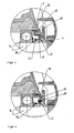
- the washing machine according to FIG. 1 has a substantially cylindrical tub (1) and a rotatably mounted therein, also cylindrical drum (2) for receiving the laundry (not shown).
- the tub (1) is preferably made of alkali-resistant plastic. He has in the center of its bottom (3) has an opening (4), behind which a bearing housing (5) is arranged. It is carried by a bearing cross, not shown, which (not shown) of the tub (1) or directly to the bottom (3) is fixed with its outer ends at the edge of the lateral surface.
- a shaft journal (7) connected to the drum (2) via a flange (6) is passed through the opening (4).
- the bearing for the drum (2) consists of a front and a rear radial ball bearing (8, 9), which are fixed by press fitting in the inner bore (10) of the bearing housing (5) and receive the shaft journal (7).
- the front bearing (8) is protected by a sealing arrangement described below, which is inserted either in the inner bore (10) of the bearing housing (5) or the front opening (4) of the suds container bottom (3).
- Sealing arrangement shown includes a resilient radial shaft seal (11), for example made of NBR, which rests with three dynamically stressed sealing lips (12, 13, 14) on a raceway (15).
- the race (15) is fitted by press fitting on the shaft journal (7).
- the sealing lips (12, 13, 14) are vulcanized to a stiffening ring (19) made of galvanized sheet steel, which has a rectangular profile and thereby a radially directed portion (20) and an axially directed portion (21).
- a circumferential spiral spring (22) on the sealing lip (14) provides better contact with the race (15).
- a pre-shielding which is preceded by the lye side of the radial shaft sealing ring (11).
- This pre-shielding consists of a circumferential ring (24) with a substantially v-shaped, outwardly open cross-section and an edge extension (25) which is formed on the left in the figure, that is, the lye-side rear leg (26).
- the pre-shielding thus formed surrounds the Shaft (7) and protects with its circulating ring (24) the radial shaft sealing ring (11) against a sprinkling with liquor, which is entrained by the rotating drum (2) from the lower portion of the tub (1) in the upper region.
- the union region (28) of the two legs (26, 27) of the pre-shielding therefore extends approximately into the region of the raceway (15).
- the edge projection (25) bears against the edge of the suds container bottom (3) formed by the opening (4) with a seal (29) arranged on its outer peripheral surface.
- the edge is thickened and equipped with an axially directed contact surface (30).
- the seal (29) consists of a thermoplastic elastomer (TPE-O), the remainder of the pre-shielding is made of an alkali-resistant plastic, such as polypropylene.
- the entire pre-shield can be made in a two-component injection molding process.
- the seal (29) forms with respect to the tub base (3) the statically stressed part of the seal assembly.
- the axial region of the stiffening ring (19) on its outer peripheral surface with a vulcanized seal (23) may be provided.
- FIG. 2 shows a sealing arrangement in which instead of a radial shaft sealing ring made of elastic material, a seal (31) made of PTFE is used, which is mounted on a resilient metal ring.
- the pre-shielding is up to the seal (29, s. FIG. 1 a) identical to the one in FIG. 1 illustrated embodiment.
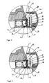
- the seal arrangement in FIG. 4 includes a Vorableung as in the FIGS. 1 and 2 , wherein on the lye-side rear leg (26) a holding web (33) is integrally formed. On this retaining web (33) a radial shaft seal (11) is attached and fixed non-positively with a clamping band (34).
- All four pre-shields described above may have a drainage bore (not shown) which is in the installed state at about the six o'clock position. About this is Liquid which, despite Vorableung has penetrated into the cavity in front of the radial shaft sealing ring (11), returned to the lower region of the tub (1).
- FIGS. 5 and 6 show seal assemblies in which the Vorabminungen have a ring (35) with u-shaped profile. They are also made of alkali-resistant plastic, such as polypropylene. At the lye-side rear leg (36), a fastening pin (37) is integrally formed. Another component of the illustrated sealing arrangements is a stiffening ring (38) which has a rectangular profile. In the radial leg (39) has an opening (40) is arranged, through which the fastening pin (37) extends. As a result, stiffening ring (38) and pre-shielding can be connected to each other, either by welding ( FIG. 5 ) or by latching ( FIG. 6 ). They clamp between them a radial shaft sealing ring (11).
- This radial shaft seal (11) has the from the FIGS. 1 . 3 and 4 known three radial sealing lips (12, 13, 14) as dynamically stressed seals.
- an axially directed portion (42a) of the radial shaft sealing ring (11) is pressed by the axial leg (41) of the stiffening ring (38) to the contact surface at the edge of the tub base (3).
- the bearings can, as in the FIGS. 1a and 3 to 6 shown, between the front bearing (8) and the race (15) one or two disc springs (42) on the shaft journal (7) to be pushed.
- FIGS. 7 to 9 show storage arrangements of washing machines, in which at least the tub base (3) must be made of a resistant alkali plastic.
- the bearing housing (5) extends beyond the front bearing (8) and thus forms an extension (44) around which the edge (45) of the tub bottom (3) is placed in the region of the opening (4). At least part of the pre-shielding is molded onto this edge (45).
- FIG. 7 shows a variant in which the Vorabcanung consists of a circulating ring (46) with a V-shaped profile and is fully molded onto the edge (45).
- FIG. 1 illustrated radial shaft sealing ring (11), wherein the axial region of the stiffening ring (19) with its vulcanized seal (23) directly on the edge (45) of the tub base (3) is applied.
- the pre-shielding is designed as a U-shaped circular ring.
- the web (47) made of alkali-resistant plastic and molded onto the tub bottom (3), the latter itself forms the lye side rear leg of Vorabprocessung.
- a ring (48) made of stainless steel is clamped on the bridge and has a rectangular profile.
- the lye-side front leg (49) of the pre-shielding is formed.
- a web (50) formed in the area outside the bearing housing (5) to the lye container bottom (3) concentric with the opening a web (50) formed.
- radial shaft seal (11) used.
- FIG. 9 the pre-shielding is identical to the one in FIG. 8 shown arrangement.
Landscapes
- Engineering & Computer Science (AREA)
- General Engineering & Computer Science (AREA)
- Textile Engineering (AREA)
- Mechanical Engineering (AREA)
- Main Body Construction Of Washing Machines And Laundry Dryers (AREA)
- Sealing Of Bearings (AREA)
- Sealing Using Fluids, Sealing Without Contact, And Removal Of Oil (AREA)
- Cleaning By Liquid Or Steam (AREA)
- Centrifugal Separators (AREA)
Claims (5)
- Machine à laver avec une cuve de lessivage (1) essentiellement cylindrique et avec un tambour (2) également cylindrique qui y est supporté en rotation, un tourillon d'arbre (7) étant disposé sur le fond du tambour (2) pour le support en tourillon d'arbreement de celui-ci, tourillon d'arbre qui s'étend à travers une ouverture (4) dans le fond de cuve de lessivage (3) et qui est reçu par au moins deux paliers (8, 9) qui sont disposés à l'intérieur d'un logement de palier (5), et un dispositif d'étanchéité étant prévu pour l'étanchéité de l'ouverture (4), dispositif qui appuie, par une partie d'étanchéité (12, 13, 14), soumise à des contraintes dynamiques, contre le tourillon d'arbre (7) ou contre une bague de roulement (15) disposée sur le tourillon d'arbre (7) et, par une partie d'étanchéité (23, 29), soumise à des contraintes statiques, contre le fond de cuve de lessivage (3) ou contre le logement de palier (5), et qui possède côté lessive un pré-bouclier devant ces parties d'étanchéité,
caractérisée en ce que
le pré-bouclier est constitué sous forme d'anneau périphérique (24, 46) entourant le tourillon d'arbre (7) avec une section transversale ouverte vers l'extérieur, essentiellement en forme de v ou de u, de sorte que la zone de jonction face à l'ouverture de section transversale s'étend depuis deux branches (26, 27), formant le U ou le V, du pré-bouclier jusqu'à approximativement dans la zone du tourillon d'arbre (7) ou de la bague de roulement (15), au moins une partie du pré-bouclier étant réalisée dans une matière plastique résistante à la lessive, et au moins cette partie du pré-bouclier étant formée sur le fond de cuve de lessivage (3) qui est réalisé dans une matière plastique résistante à la lessive. - Machine à laver avec un dispositif d'étanchéité selon la revendication 1,
caractérisée en ce que
le pré-bouclier fait office de support pour au moins une partie d'étanchéité. - Machine à laver avec un dispositif d'étanchéité selon au moins une des revendications 1 à 2,
caractérisée en ce que,
côté lessive, il est disposé un anneau de renfort (38) derrière la partie d'étanchéité (12, 13, 14) soumise à des contraintes dynamiques et derrière la partie d'étanchéité (23, 29) soumise à des contraintes statiques. - Machine à laver avec un dispositif d'étanchéité selon la revendication 3,
caractérisée en ce que
l'anneau de renfort (38) est fixé sur le pré-bouclier avec intercalation de la partie d'étanchéité (12, 13, 14) soumise à des contraintes dynamiques et de la partie d'étanchéité (23, 29) soumise à des contraintes statiques. - Machine à laver avec un dispositif d'étanchéité selon au moins une des revendications 1 à 4,
caractérisée en ce que
le pré-bouclier est équipé d'un alésage d'écoulement qui, dans l'état monté, est situé environ dans la position six heures.
Applications Claiming Priority (2)
| Application Number | Priority Date | Filing Date | Title |
|---|---|---|---|
| DE10342262A DE10342262B3 (de) | 2003-09-11 | 2003-09-11 | Waschmaschine mit einer Dichtungsanordnung |
| DE10342262 | 2003-09-11 |
Publications (3)
| Publication Number | Publication Date |
|---|---|
| EP1514965A2 EP1514965A2 (fr) | 2005-03-16 |
| EP1514965A3 EP1514965A3 (fr) | 2007-10-10 |
| EP1514965B1 true EP1514965B1 (fr) | 2010-10-27 |
Family
ID=33305260
Family Applications (1)
| Application Number | Title | Priority Date | Filing Date |
|---|---|---|---|
| EP04018996A Expired - Lifetime EP1514965B1 (fr) | 2003-09-11 | 2004-08-11 | Machine à laver avec dispositif d'étanchéité |
Country Status (4)
| Country | Link |
|---|---|
| EP (1) | EP1514965B1 (fr) |
| AT (1) | ATE486164T1 (fr) |
| DE (2) | DE10342262B3 (fr) |
| ES (1) | ES2351584T3 (fr) |
Families Citing this family (8)
| Publication number | Priority date | Publication date | Assignee | Title |
|---|---|---|---|---|
| DE10342254B3 (de) * | 2003-09-11 | 2004-11-18 | Miele & Cie. Kg | Waschmaschine mit einer Dichtungsanordnung |
| DE102005062891B3 (de) * | 2005-12-29 | 2007-08-30 | Ab Skf | Lageranordnung |
| DE112006003882T5 (de) | 2006-05-02 | 2009-04-16 | Lg Electronics Inc. | Trommelwaschmaschine E |
| EP2708630B1 (fr) | 2012-09-14 | 2019-04-24 | Samsung Electronics Co., Ltd. | Machine à laver à tambour |
| DE102014206634A1 (de) * | 2014-04-07 | 2015-10-08 | BSH Hausgeräte GmbH | Lageranordnung und Waschmaschine mit einer Lageranordnung |
| DE102018202762A1 (de) * | 2018-02-23 | 2019-08-29 | BSH Hausgeräte GmbH | Waschmaschine mit einer Dichtanordnung für eine Lageranordnung eines Laugenbehälters der Waschmaschine |
| CN110791922A (zh) * | 2018-08-01 | 2020-02-14 | 青岛海尔滚筒洗衣机有限公司 | 一种外筒及滚筒洗衣机 |
| CN109652949B (zh) * | 2018-12-06 | 2020-10-23 | 无锡小天鹅电器有限公司 | 衣物处理装置 |
Family Cites Families (5)
| Publication number | Priority date | Publication date | Assignee | Title |
|---|---|---|---|---|
| US2835123A (en) * | 1954-06-28 | 1958-05-20 | Galinski Roman | Washing apparatus with liquid seal for rotating shaft |
| DE3838824C2 (de) * | 1988-11-17 | 1995-06-08 | Kugelfischer G Schaefer & Co | Dichtung, bestehend aus mehreren Dichtringen |
| EP0579849B1 (fr) * | 1992-07-20 | 1997-01-15 | WASCHGERÄTE GmbH i.L. | Machine à laver à tambour avec une cuve en matière plastique |
| DE4422853C2 (de) * | 1994-06-30 | 2003-06-12 | Miele & Cie | Lagerabdichtung für Radial-Wälzlager |
| DE10133892A1 (de) * | 2001-07-12 | 2003-01-30 | Miele & Cie | Dichtungssystem zur Abdichtung von zwei relativ zueinander verdrehbaren Maschinenelementen |
-
2003
- 2003-09-11 DE DE10342262A patent/DE10342262B3/de not_active Expired - Fee Related
-
2004
- 2004-08-11 DE DE502004011817T patent/DE502004011817D1/de not_active Expired - Lifetime
- 2004-08-11 ES ES04018996T patent/ES2351584T3/es not_active Expired - Lifetime
- 2004-08-11 EP EP04018996A patent/EP1514965B1/fr not_active Expired - Lifetime
- 2004-08-11 AT AT04018996T patent/ATE486164T1/de active
Also Published As
| Publication number | Publication date |
|---|---|
| EP1514965A2 (fr) | 2005-03-16 |
| ATE486164T1 (de) | 2010-11-15 |
| DE10342262B3 (de) | 2004-11-18 |
| ES2351584T3 (es) | 2011-02-08 |
| DE502004011817D1 (de) | 2010-12-09 |
| EP1514965A3 (fr) | 2007-10-10 |
Similar Documents
| Publication | Publication Date | Title |
|---|---|---|
| EP1514966B1 (fr) | Machine à laver avec dispositif d'étanchéité | |
| DE69800162T2 (de) | Dichtung für Wälzlager | |
| DE102013218635B4 (de) | Dichtungsanordnung für Radlager mit vorgespanntem Schleuderblech | |
| DE3148530C2 (fr) | ||
| DE69608003T2 (de) | Lager | |
| DE69004080T2 (de) | Kassettendichtung und ihr herstellungsverfahren. | |
| WO2004065806A1 (fr) | Module d'etancheite pour un coussinet | |
| DE3412484A1 (de) | Oeldichtungsanordnung | |
| WO2019114853A1 (fr) | Arrangement d'étanchéité d'un palier de roue | |
| DE102020112044A1 (de) | Wälzlager mit Schleuderscheibe | |
| DE3207488C2 (fr) | ||
| DE4422853A1 (de) | Lagerabdichtung für Radial-Wälzlager | |
| EP2899307B1 (fr) | Lessive pour un lave-linge | |
| DE10342262B3 (de) | Waschmaschine mit einer Dichtungsanordnung | |
| DE69418281T2 (de) | Lagereinheit mit interner Dichtung | |
| DE3616999A1 (de) | Dichtung, insbesondere fuer waelzlager | |
| DE102008006656A1 (de) | Kupplungsausrücklagereinrichtung | |
| WO2002044578A1 (fr) | Joint pour butee d'embrayage | |
| DE602005003239T2 (de) | Mehrstufige Öldichtung für einen Werkzeugmaschinenantrieb | |
| DE4408831A1 (de) | Abdichtung für Gelenkkreuzbüchsen | |
| DE19938246C5 (de) | Dichtungsanordnung für ein Lager | |
| DE8632410U1 (de) | Dichtungsgarnitur, insbesondere für Eisenbahnachsenlager | |
| DE10140837C1 (de) | Dichtungsanordnung | |
| DE102022130974A1 (de) | Vordichtungselement mit einer Rotationsachse für eine dynamische Wellendichtungsanordnung, eine Wellendichtungsanordnung mit einer Rotationsachse für eine dynamische Dichtung, sowie eine Wellenbaugruppe | |
| DE10252011A1 (de) | Waschmaschine mit Dichtungsanordnung |
Legal Events
| Date | Code | Title | Description |
|---|---|---|---|
| PUAI | Public reference made under article 153(3) epc to a published international application that has entered the european phase |
Free format text: ORIGINAL CODE: 0009012 |
|
| AK | Designated contracting states |
Kind code of ref document: A2 Designated state(s): AT BE BG CH CY CZ DE DK EE ES FI FR GB GR HU IE IT LI LU MC NL PL PT RO SE SI SK TR |
|
| AX | Request for extension of the european patent |
Extension state: AL HR LT LV MK |
|
| PUAL | Search report despatched |
Free format text: ORIGINAL CODE: 0009013 |
|
| AK | Designated contracting states |
Kind code of ref document: A3 Designated state(s): AT BE BG CH CY CZ DE DK EE ES FI FR GB GR HU IE IT LI LU MC NL PL PT RO SE SI SK TR |
|
| AX | Request for extension of the european patent |
Extension state: AL HR LT LV MK |
|
| 17P | Request for examination filed |
Effective date: 20071025 |
|
| AKX | Designation fees paid |
Designated state(s): AT BE BG CH CY CZ DE DK EE ES FI FR GB GR HU IE IT LI LU MC NL PL PT RO SE SI SK TR |
|
| 17Q | First examination report despatched |
Effective date: 20090806 |
|
| GRAP | Despatch of communication of intention to grant a patent |
Free format text: ORIGINAL CODE: EPIDOSNIGR1 |
|
| GRAS | Grant fee paid |
Free format text: ORIGINAL CODE: EPIDOSNIGR3 |
|
| GRAA | (expected) grant |
Free format text: ORIGINAL CODE: 0009210 |
|
| AK | Designated contracting states |
Kind code of ref document: B1 Designated state(s): AT BE BG CH CY CZ DE DK EE ES FI FR GB GR HU IE IT LI LU MC NL PL PT RO SE SI SK TR |
|
| REG | Reference to a national code |
Ref country code: GB Ref legal event code: FG4D Free format text: NOT ENGLISH |
|
| REG | Reference to a national code |
Ref country code: CH Ref legal event code: EP |
|
| REG | Reference to a national code |
Ref country code: IE Ref legal event code: FG4D Free format text: LANGUAGE OF EP DOCUMENT: GERMAN Ref country code: GB Ref legal event code: 746 Effective date: 20101102 |
|
| REF | Corresponds to: |
Ref document number: 502004011817 Country of ref document: DE Date of ref document: 20101209 Kind code of ref document: P |
|
| REG | Reference to a national code |
Ref country code: ES Ref legal event code: FG2A Effective date: 20110127 |
|
| REG | Reference to a national code |
Ref country code: NL Ref legal event code: VDEP Effective date: 20101027 |
|
| REG | Reference to a national code |
Ref country code: IE Ref legal event code: FD4D |
|
| PG25 | Lapsed in a contracting state [announced via postgrant information from national office to epo] |
Ref country code: PT Free format text: LAPSE BECAUSE OF FAILURE TO SUBMIT A TRANSLATION OF THE DESCRIPTION OR TO PAY THE FEE WITHIN THE PRESCRIBED TIME-LIMIT Effective date: 20110228 Ref country code: FI Free format text: LAPSE BECAUSE OF FAILURE TO SUBMIT A TRANSLATION OF THE DESCRIPTION OR TO PAY THE FEE WITHIN THE PRESCRIBED TIME-LIMIT Effective date: 20101027 Ref country code: NL Free format text: LAPSE BECAUSE OF FAILURE TO SUBMIT A TRANSLATION OF THE DESCRIPTION OR TO PAY THE FEE WITHIN THE PRESCRIBED TIME-LIMIT Effective date: 20101027 Ref country code: SI Free format text: LAPSE BECAUSE OF FAILURE TO SUBMIT A TRANSLATION OF THE DESCRIPTION OR TO PAY THE FEE WITHIN THE PRESCRIBED TIME-LIMIT Effective date: 20101027 Ref country code: SE Free format text: LAPSE BECAUSE OF FAILURE TO SUBMIT A TRANSLATION OF THE DESCRIPTION OR TO PAY THE FEE WITHIN THE PRESCRIBED TIME-LIMIT Effective date: 20101027 Ref country code: BG Free format text: LAPSE BECAUSE OF FAILURE TO SUBMIT A TRANSLATION OF THE DESCRIPTION OR TO PAY THE FEE WITHIN THE PRESCRIBED TIME-LIMIT Effective date: 20110127 |
|
| PG25 | Lapsed in a contracting state [announced via postgrant information from national office to epo] |
Ref country code: GR Free format text: LAPSE BECAUSE OF FAILURE TO SUBMIT A TRANSLATION OF THE DESCRIPTION OR TO PAY THE FEE WITHIN THE PRESCRIBED TIME-LIMIT Effective date: 20110128 |
|
| PG25 | Lapsed in a contracting state [announced via postgrant information from national office to epo] |
Ref country code: CZ Free format text: LAPSE BECAUSE OF FAILURE TO SUBMIT A TRANSLATION OF THE DESCRIPTION OR TO PAY THE FEE WITHIN THE PRESCRIBED TIME-LIMIT Effective date: 20101027 Ref country code: EE Free format text: LAPSE BECAUSE OF FAILURE TO SUBMIT A TRANSLATION OF THE DESCRIPTION OR TO PAY THE FEE WITHIN THE PRESCRIBED TIME-LIMIT Effective date: 20101027 Ref country code: IE Free format text: LAPSE BECAUSE OF FAILURE TO SUBMIT A TRANSLATION OF THE DESCRIPTION OR TO PAY THE FEE WITHIN THE PRESCRIBED TIME-LIMIT Effective date: 20101027 |
|
| PG25 | Lapsed in a contracting state [announced via postgrant information from national office to epo] |
Ref country code: RO Free format text: LAPSE BECAUSE OF FAILURE TO SUBMIT A TRANSLATION OF THE DESCRIPTION OR TO PAY THE FEE WITHIN THE PRESCRIBED TIME-LIMIT Effective date: 20101027 Ref country code: DK Free format text: LAPSE BECAUSE OF FAILURE TO SUBMIT A TRANSLATION OF THE DESCRIPTION OR TO PAY THE FEE WITHIN THE PRESCRIBED TIME-LIMIT Effective date: 20101027 Ref country code: SK Free format text: LAPSE BECAUSE OF FAILURE TO SUBMIT A TRANSLATION OF THE DESCRIPTION OR TO PAY THE FEE WITHIN THE PRESCRIBED TIME-LIMIT Effective date: 20101027 Ref country code: PL Free format text: LAPSE BECAUSE OF FAILURE TO SUBMIT A TRANSLATION OF THE DESCRIPTION OR TO PAY THE FEE WITHIN THE PRESCRIBED TIME-LIMIT Effective date: 20101027 |
|
| PLBE | No opposition filed within time limit |
Free format text: ORIGINAL CODE: 0009261 |
|
| STAA | Information on the status of an ep patent application or granted ep patent |
Free format text: STATUS: NO OPPOSITION FILED WITHIN TIME LIMIT |
|
| 26N | No opposition filed |
Effective date: 20110728 |
|
| REG | Reference to a national code |
Ref country code: ES Ref legal event code: GC2A Effective date: 20110926 |
|
| REG | Reference to a national code |
Ref country code: DE Ref legal event code: R097 Ref document number: 502004011817 Country of ref document: DE Effective date: 20110728 |
|
| BERE | Be: lapsed |
Owner name: MIELE & CIE. K.G. Effective date: 20110831 |
|
| PG25 | Lapsed in a contracting state [announced via postgrant information from national office to epo] |
Ref country code: MC Free format text: LAPSE BECAUSE OF NON-PAYMENT OF DUE FEES Effective date: 20110831 |
|
| REG | Reference to a national code |
Ref country code: CH Ref legal event code: PL |
|
| PG25 | Lapsed in a contracting state [announced via postgrant information from national office to epo] |
Ref country code: CH Free format text: LAPSE BECAUSE OF NON-PAYMENT OF DUE FEES Effective date: 20110831 Ref country code: LI Free format text: LAPSE BECAUSE OF NON-PAYMENT OF DUE FEES Effective date: 20110831 |
|
| PG25 | Lapsed in a contracting state [announced via postgrant information from national office to epo] |
Ref country code: BE Free format text: LAPSE BECAUSE OF NON-PAYMENT OF DUE FEES Effective date: 20110831 |
|
| REG | Reference to a national code |
Ref country code: AT Ref legal event code: MM01 Ref document number: 486164 Country of ref document: AT Kind code of ref document: T Effective date: 20110811 |
|
| PG25 | Lapsed in a contracting state [announced via postgrant information from national office to epo] |
Ref country code: AT Free format text: LAPSE BECAUSE OF NON-PAYMENT OF DUE FEES Effective date: 20110811 |
|
| PG25 | Lapsed in a contracting state [announced via postgrant information from national office to epo] |
Ref country code: CY Free format text: LAPSE BECAUSE OF EXPIRATION OF PROTECTION Effective date: 20101027 Ref country code: LU Free format text: LAPSE BECAUSE OF NON-PAYMENT OF DUE FEES Effective date: 20110811 |
|
| PG25 | Lapsed in a contracting state [announced via postgrant information from national office to epo] |
Ref country code: TR Free format text: LAPSE BECAUSE OF FAILURE TO SUBMIT A TRANSLATION OF THE DESCRIPTION OR TO PAY THE FEE WITHIN THE PRESCRIBED TIME-LIMIT Effective date: 20101027 |
|
| PG25 | Lapsed in a contracting state [announced via postgrant information from national office to epo] |
Ref country code: HU Free format text: LAPSE BECAUSE OF FAILURE TO SUBMIT A TRANSLATION OF THE DESCRIPTION OR TO PAY THE FEE WITHIN THE PRESCRIBED TIME-LIMIT Effective date: 20101027 |
|
| REG | Reference to a national code |
Ref country code: FR Ref legal event code: PLFP Year of fee payment: 13 |
|
| REG | Reference to a national code |
Ref country code: FR Ref legal event code: PLFP Year of fee payment: 14 |
|
| REG | Reference to a national code |
Ref country code: FR Ref legal event code: PLFP Year of fee payment: 15 |
|
| PGFP | Annual fee paid to national office [announced via postgrant information from national office to epo] |
Ref country code: IT Payment date: 20220819 Year of fee payment: 19 Ref country code: GB Payment date: 20220823 Year of fee payment: 19 Ref country code: ES Payment date: 20220908 Year of fee payment: 19 Ref country code: DE Payment date: 20220831 Year of fee payment: 19 |
|
| PGFP | Annual fee paid to national office [announced via postgrant information from national office to epo] |
Ref country code: FR Payment date: 20220824 Year of fee payment: 19 |
|
| P01 | Opt-out of the competence of the unified patent court (upc) registered |
Effective date: 20230529 |
|
| REG | Reference to a national code |
Ref country code: DE Ref legal event code: R119 Ref document number: 502004011817 Country of ref document: DE |
|
| GBPC | Gb: european patent ceased through non-payment of renewal fee |
Effective date: 20230811 |
|
| PG25 | Lapsed in a contracting state [announced via postgrant information from national office to epo] |
Ref country code: GB Free format text: LAPSE BECAUSE OF NON-PAYMENT OF DUE FEES Effective date: 20230811 |
|
| PG25 | Lapsed in a contracting state [announced via postgrant information from national office to epo] |
Ref country code: IT Free format text: LAPSE BECAUSE OF NON-PAYMENT OF DUE FEES Effective date: 20230811 Ref country code: GB Free format text: LAPSE BECAUSE OF NON-PAYMENT OF DUE FEES Effective date: 20230811 Ref country code: FR Free format text: LAPSE BECAUSE OF NON-PAYMENT OF DUE FEES Effective date: 20230831 Ref country code: DE Free format text: LAPSE BECAUSE OF NON-PAYMENT OF DUE FEES Effective date: 20240301 |
|
| REG | Reference to a national code |
Ref country code: ES Ref legal event code: FD2A Effective date: 20240927 |
|
| PG25 | Lapsed in a contracting state [announced via postgrant information from national office to epo] |
Ref country code: ES Free format text: LAPSE BECAUSE OF NON-PAYMENT OF DUE FEES Effective date: 20230812 |
|
| PG25 | Lapsed in a contracting state [announced via postgrant information from national office to epo] |
Ref country code: ES Free format text: LAPSE BECAUSE OF NON-PAYMENT OF DUE FEES Effective date: 20230812 |