EP1514973A2 - Panneau en treillis et construction de structures avec tels panneaux - Google Patents
Panneau en treillis et construction de structures avec tels panneaux Download PDFInfo
- Publication number
- EP1514973A2 EP1514973A2 EP04020870A EP04020870A EP1514973A2 EP 1514973 A2 EP1514973 A2 EP 1514973A2 EP 04020870 A EP04020870 A EP 04020870A EP 04020870 A EP04020870 A EP 04020870A EP 1514973 A2 EP1514973 A2 EP 1514973A2
- Authority
- EP
- European Patent Office
- Prior art keywords
- engagement
- parts
- skeleton
- panel
- recessed
- Prior art date
- Legal status (The legal status is an assumption and is not a legal conclusion. Google has not performed a legal analysis and makes no representation as to the accuracy of the status listed.)
- Withdrawn
Links
- 238000010276 construction Methods 0.000 title abstract description 7
- 238000009751 slip forming Methods 0.000 claims description 10
- 238000000034 method Methods 0.000 claims description 8
- 125000006850 spacer group Chemical group 0.000 description 10
- XAGFODPZIPBFFR-UHFFFAOYSA-N aluminium Chemical compound [Al] XAGFODPZIPBFFR-UHFFFAOYSA-N 0.000 description 8
- 229910052782 aluminium Inorganic materials 0.000 description 8
- 239000011521 glass Substances 0.000 description 7
- 230000000149 penetrating effect Effects 0.000 description 5
- 230000000694 effects Effects 0.000 description 3
- 239000000853 adhesive Substances 0.000 description 1
- 230000001070 adhesive effect Effects 0.000 description 1
- 238000012986 modification Methods 0.000 description 1
- 230000004048 modification Effects 0.000 description 1
- 239000005011 phenolic resin Substances 0.000 description 1
- 239000011347 resin Substances 0.000 description 1
- 229920005989 resin Polymers 0.000 description 1
- 238000010079 rubber tapping Methods 0.000 description 1
Images


Classifications
-
- E—FIXED CONSTRUCTIONS
- E04—BUILDING
- E04B—GENERAL BUILDING CONSTRUCTIONS; WALLS, e.g. PARTITIONS; ROOFS; FLOORS; CEILINGS; INSULATION OR OTHER PROTECTION OF BUILDINGS
- E04B2/00—Walls, e.g. partitions, for buildings; Wall construction with regard to insulation; Connections specially adapted to walls
- E04B2/74—Removable non-load-bearing partitions; Partitions with a free upper edge
- E04B2/7407—Removable non-load-bearing partitions; Partitions with a free upper edge assembled using frames with infill panels or coverings only; made-up of panels and a support structure incorporating posts
- E04B2/7416—Removable non-load-bearing partitions; Partitions with a free upper edge assembled using frames with infill panels or coverings only; made-up of panels and a support structure incorporating posts with free upper edge, e.g. for use as office space dividers
- E04B2/7422—Removable non-load-bearing partitions; Partitions with a free upper edge assembled using frames with infill panels or coverings only; made-up of panels and a support structure incorporating posts with free upper edge, e.g. for use as office space dividers with separate framed panels without intermediary support posts
- E04B2/7425—Details of connection of panels
-
- E—FIXED CONSTRUCTIONS
- E04—BUILDING
- E04B—GENERAL BUILDING CONSTRUCTIONS; WALLS, e.g. PARTITIONS; ROOFS; FLOORS; CEILINGS; INSULATION OR OTHER PROTECTION OF BUILDINGS
- E04B2/00—Walls, e.g. partitions, for buildings; Wall construction with regard to insulation; Connections specially adapted to walls
- E04B2/74—Removable non-load-bearing partitions; Partitions with a free upper edge
- E04B2/7407—Removable non-load-bearing partitions; Partitions with a free upper edge assembled using frames with infill panels or coverings only; made-up of panels and a support structure incorporating posts
- E04B2/7416—Removable non-load-bearing partitions; Partitions with a free upper edge assembled using frames with infill panels or coverings only; made-up of panels and a support structure incorporating posts with free upper edge, e.g. for use as office space dividers
- E04B2/7422—Removable non-load-bearing partitions; Partitions with a free upper edge assembled using frames with infill panels or coverings only; made-up of panels and a support structure incorporating posts with free upper edge, e.g. for use as office space dividers with separate framed panels without intermediary support posts
- E04B2/7424—Glazing details
-
- E—FIXED CONSTRUCTIONS
- E04—BUILDING
- E04C—STRUCTURAL ELEMENTS; BUILDING MATERIALS
- E04C2/00—Building elements of relatively thin form for the construction of parts of buildings, e.g. sheet materials, slabs, or panels
- E04C2/30—Building elements of relatively thin form for the construction of parts of buildings, e.g. sheet materials, slabs, or panels characterised by the shape or structure
- E04C2/38—Building elements of relatively thin form for the construction of parts of buildings, e.g. sheet materials, slabs, or panels characterised by the shape or structure with attached ribs, flanges, or the like, e.g. framed panels
- E04C2/384—Building elements of relatively thin form for the construction of parts of buildings, e.g. sheet materials, slabs, or panels characterised by the shape or structure with attached ribs, flanges, or the like, e.g. framed panels with a metal frame
Definitions
- the present invention relates to a lattice panel and a lattice panel constructing method. More particularly, the present invention relates to the lattice panel, in which, cross-shaped first skeleton members, L-shaped second skeleton members and frame members are appropriately combined as necessary, so that a wall structure having a desired strength may be obtained easily.
- patent documents 1, 2, 3, 4 and 5 there are several disclosures regarding so-called "panel construction", for example, patent documents 1, 2, 3, 4 and 5, as follows:
- a lattice panel comprising: a panel body, assembled by continuously connecting several numbers of cross-shaped first skeleton members, and by continuously connecting L-shaped second skeleton members to the outer periphery of the first skeleton members; and frame members attached to the outer periphery of the panel body.
- the lattice panel as claimed in claim 1 further characterized in that: the first skeleton member has engagement parts at the end of four elongating parts, so that the first skeleton members adjacent to each other may be connected by engaging the engagement parts with each other.
- the lattice panel as claimed in claim 1 further characterized in that: the second skeleton member also has engagement parts at the end of two elongating parts, respectively in the same shape as that of the engagement part of the first skeleton member, so that the second skeleton member may be connected to the adjacent first skeleton member, by engaging the engagement part of the second skeleton member with the engagement part of the first skeleton member.
- the lattice panel as claimed in claim 2 further characterized in that: the engagement part is comprising, a first recessed part, a half-round shape of a second recessed part continuously formed by following the first recessed part, a first salient part provided at the outer side of the second recessed part, and a second salient part protruding at the end of the engagement part.
- the lattice panel as claimed in claim 3 further characterized in that: the engagement part is comprising, a first recessed part, a half-round shape of a second recessed part continuously formed by following the first recessed part, a first salient part provided at the outer side of the second recessed part, and a second salient part protruding at the end of the engagement part.
- the lattice panel as claimed in claim 4 further characterized in that: the first recessed part is engaged with the second salient part of another first skeleton member to be connected to each other, respectively having hooks at the first recessed part and the second salient part in order to prevent detachment thereof in the elongating direction.
- the lattice panel as claimed in claim 5 further characterized in that: the first recessed part is engaged with the second salient part of another first skeleton member to be connected to each other, respectively having hooks at the first recessed part and the second salient part in order to prevent detachment thereof in the elongating direction.
- the lattice panel as claimed in claim 4 further characterized in that: a hollow circle is formed by the second recessed parts when the engagement parts are connected to each other, and the engagement parts are fixed by inserting and adhering an axial member into the hollow circle.
- the lattice panel as claimed in claim 5 further characterized in that: a hollow circle is formed by the second recessed parts when the engagement parts are connected to each other, and the engagement parts are fixed by inserting and adhering an axial member into the hollow circle.
- the lattice panel as claimed in claim 4 further characterized in that: a hollow circle is formed by the second recessed parts when the engagement parts are connected to each other, and the engagement parts are bound and fixed by engagement with a screw member inserted into the hollow circle.
- the lattice panel as claimed in claim 5 further characterized in that: a hollow circle is formed by the second recessed parts when the engagement parts are connected to each other, and the engagement parts are bound and fixed by engagement with a screw member inserted into the hollow circle.
- the lattice panel as claimed in claim 1 further characterized in that: a flat part is formed at an L-shape corner of the second skeleton member, and the second skeleton member is fixed on the frame member via the flat part.
- a lattice panel comprising: first panels according to any one claim of claims 1 through 12; and second panels formed only by the frame members, characterized in that: several numbers of the first panels and the second panels are connected to each other.
- a lattice panel constructing method comprising steps of: continuously connecting several numbers of cross-shaped first skeleton members, by engaging engagement parts with each other and by fixing through fixing means; continuously connecting L-shaped second skeleton members to the outer periphery of the first skeleton members, by engaging engagement parts with each other and by fixing through fixing means, thus assembling a panel body; constructing first panels by attaching frame members to the outer periphery of the panel body; and continuously connecting several numbers of the first panels.
- the lattice panel constructing method as claimed in claim 14 further comprising steps of: preparing second panels formed only by the frame members and continuously connecting appropriate numbers of the second panels to the first panels.
- the lattice panel according to the present invention has the following merits.
- the lattice panel has the panel body, assembled by continuously connecting several numbers of cross-shaped first skeleton members, and by continuously connecting L-shaped second skeleton members to the outer periphery of the first skeleton members, and the frame members attached to the outer periphery of the panel body.
- the first skeleton member has the engagement parts at the end of four elongating parts, so that the first skeleton members adjacent to each other may be connected by engaging the engagement parts with each other.
- the first skeleton members adjacent to each other may be connected by engaging the engagement parts with each other.
- the second skeleton member also has the engagement parts at the end of two elongating parts, respectively in the same shape as that of the engagement part of the first skeleton member, so that the second skeleton member may be connected to the adjacent first skeleton member, by engaging the engagement part of the second skeleton member with the engagement part of the first skeleton member.
- the engagement part is comprising, the first recessed part, the half-round shape of the second recessed part continuously formed by following the first recessed part, the first salient part provided at the outer side of the second recessed part, and the second salient part protruding at the end of the engagement part.
- the engagement part is comprising, the first recessed part, the half-round shape of the second recessed part continuously formed by following the first recessed part, the first salient part provided at the outer side of the second recessed part, and the second salient part protruding at the end of the engagement part.
- the first recessed part is engaged with the second salient part of another first skeleton member to be connected to each other, respectively having the hooks at the first recessed part and the second salient part in order to prevent detachment thereof in the elongating direction.
- the detachment of the first recessed part from the second salient part may be prevented effectively.
- the hollow circle is formed by the second recessed parts when the engagement parts are connected to each other, and the engagement parts are fixed by inserting and adhering the axial member into the hollow circle.
- the hollow circle is formed by the second recessed parts when the engagement parts are connected to each other, and the engagement parts are fixed by inserting and adhering the axial member into the hollow circle.
- the hollow circle is formed by the second recessed parts when the engagement parts are connected to each other, and the engagement parts are bound and fixed by engagement with the screw member inserted into the hollow circle.
- the hollow circle is formed by the second recessed parts when the engagement parts are connected to each other, and the engagement parts are bound and fixed by engagement with the screw member inserted into the hollow circle.
- the flat part is formed at the L-shape corner of the second skeleton member, and the second skeleton member is fixed on the frame member via the flat part.
- the flat part is formed at the L-shape corner of the second skeleton member, and the second skeleton member is fixed on the frame member via the flat part.
- the lattice panel is comprising, the first panels according to any one claim of claims 1 through 12, and the second panels formed only by the frame members, and the several numbers of the first panels and the second panels are connected to each other.
- the lattice panel constructing method enables the constructing of strong lattice panel easily.
- Fig. 1 (a) is a front view showing a partial structure of a lattice panel according to the first embodiment
- Fig. 1 (b) is a side view of the lattice panel.
- a lattice panel 1 comprises first panels 3 and second panels 5 in a houndstooth check arrangement.
- the first panel 3 has several numbers of cross-shaped first skeleton members 7 connected to each other, and also has several numbers of L-shaped second skeleton members 9 connected to these first skeleton members 7 along the outer periphery of the first skeleton members 7, thus serving as a panel body 10.
- the second panel 5 only comprises the frame members 11.
- the inner part of the frame members 11 of the first panel 3 will accept, for example, a glass panel or an aluminum panel set therein, according to required situations.
- the inner part of the frame members 11 of the second panel 5 will accept, for example, a glass panel or an aluminum panel set therein, according to required situations.
- the glass panel or aluminum panel is not illustrated in Fig. 1, the explanation will be done afterward, with reference to Figs. 8 and 9.
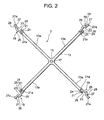
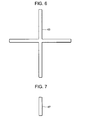
- Fig. 2 illustrates the structure of the first skeleton member 7.
- a cross-shaped skeleton member body 13 There is a cross-shaped skeleton member body 13, a center part 15 provided at the center of the skeleton member body 13, a penetrating hole 17 which is penetrating through the center part 15, and engagement parts 19 respectively provided at the end of four elongating parts 13a of the skeleton member body 13.
- Each of the engagement parts 19 has a first recessed part 21 elongated and formed in the elongating direction of the engagement part 19, a second recessed part 23 substantially in a half-round shape continuously formed by following the first recessed part 21, a third recessed part 26 formed at the end of a protrusive chip 24 comprising the first recessed part 21, a first salient part 25 at the outer part of the second recessed part 23, a second salient part 27 protruding at the and of the engagement part 19, and a third salient part 28 provided at a position between the first salient part 25 and the second salient part 27.
- the shape of the first recessed part 21 is the same as that of the second salient part 27.
- first recessed part 21 may be engaged, with the second salient part 27 of the engagement part 19 of the adjacent other first skeleton member 7.
- the first recessed part 21 has a hook 21a, and similarly, the second salient part 27 has a hook 27a.
- each of the engagement parts 19, respectively provided at the end of the four elongating parts 13a is in the same shape.
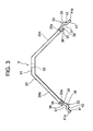
- FIG. 3 There is an L-shaped skeleton member body 29, and a flat part 31 is formed at the corner of the skeleton member body 29. A penetrating hole 32 is provided, penetrating through the flat part 31. Each end of two elongating parts 29a is provided with an engagement part 33.
- the engagement part 33 has the same structure as that of the engagement part 19 of the first skeleton member 7 as discussed above. Accordingly, the engagement part 33 has a first recessed part 35 elongated and formed in the elongating direction of the engagement part 33, a second recessed part 37 substantially in a half-round shape continuously formed by following the first recessed part 35, a third recessed part 38 formed at the end of a protrusive chip 36 comprising the first recessed part 35, a first salient part 39 at the outer part of the second recessed part 37, a second salient part 41 protruding at the and of the engagement part 33, and a third salient part 42 provided at a position between the first salient part 39 and the second salient part 41.
- the shape of the first recessed part 35 is the same as that of the second salient part 41.
- the inside of the first recessed part 35 may be engaged, with the second salient part 27 of the engagement part 19 of the adjacent first skeleton member 7.
- the first recessed part 35 has a hook 35a, and similarly, the second salient part 41 has a hook 41a.
- each of the engagement parts 19, respectively provided at the end of the two elongating parts 29a is in the same shape.
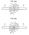
- Fig. 4 (a) shows a state in which the engagement parts 19, 19 of the first skeleton members 7, 7, adjacent to each other, are connected.
- the first recessed part 21 of the first skeleton member 7 on the one side is engaged with the second salient part 27 of the first skeleton member 7 on another side.
- the third recessed part 26 of the first skeleton member 7 on the one side is engaged with the third salient part 28 of the first skeleton member 7 on the other side.
- first recessed part 21 of the first skeleton member 7 on the other side is engaged with the second salient part 27 of the first skeleton member 7 on the one side
- third recessed part 26 of the first skeleton member 7 on the other side is engaged with the third salient part 28 of the first skeleton member 7 on the one side.
- the second recessed parts 23, 23 on the both sides form a hollow circle.
- a screw member 34 instead of the axial member 30, so that the screw member 34 may be engaged with the hollow circle formed by the second recessed parts 23, 23 of the both sides connected to each other.
- the screw member 34 has a hole 36 in which a hexagonal screwdriver (not shown) may be inserted.
- the screw member 34 has a self-tapping function, whereby an engagement thread may be made on the hollow circle formed by the second recessed parts 23, 23 on the both sides.
- FIG. 4 only shows the state in which the engagement parts 19, 19 of the first skeleton member 7, 7 adjacent to each other are connected to each other, the state in which the engagement parts 19, 33 of the first skeleton member 7 and the second skeleton member 9 are connected to each other, is substantially the same.
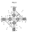
- Fig. 5 is an expanded view of the part V discussed above.
- the first spacer 43 is illustrated in Fig. 6.
- reference numeral 57 shows a seal
- the aluminum honeycomb panel 59 comprises, a frame body 61 comprising an aluminum panel, and a honeycomb member 63, in which phenol resin has been filled, incorporated in the frame body 61.
- Reference numeral 65 shows a resin edge.
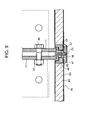
- FIG. 5 there is a second spacer 67, inserted in a position, at which the first panel 3 and the second panel 5 become in contact with each other, and at which the flat part 31 of the second skeleton member 9 is positioned.
- the second spacer 67 is illustrated in Fig. 7.
- the connecting structure of the position at which the second spacer 67 is provided, is illustrated in Figs. 10 and 11.
- a base member 81 comprising a base part 83 and a spacer part 85.
- the base part 83 is grounded, for example on grounding surface G, and fixed by a fixer comprising an anchor bolt 87 and a nut 89.
- the spacer part 85 is substantially in a shape of the letter T, and an elongating part 85a is inserted in a space between the frame members 11, 11 of the first panel 3 and the second panel 5, and is bound and fixed by connectors comprising bolts 91 and nuts 93.
- a wall structure of building may be made, by using the lattice panel 1 having the above structure.
- the pair glass 55 or the aluminum honeycomb panel 59 may be attached to the first panel 3 and the second panel 5.
- the present embodiment has the following merits.
- first skeleton members 7 there are several numbers of the cross-shaped first skeleton members 7 and the L-shaped second skeleton members 9, so that the first skeleton members 7 may be connected to each other, and also the second skeleton members 9 may be connected to the outer periphery of the first skeleton members 7, whereby the panel body is assembled, and the frame members 11 are attached to the outer periphery of the panel body, thus the lattice panel is made. Therefore, it is possible to provide a wall structure, having a relatively simple structure, and also a sufficient strength.
- the first skeleton member 7 has the engagement parts 19 at the end of four elongating parts 13a, so that the first skeleton members 7, 7 adjacent to each other may be connected by engaging the engagement parts 19, 19 with each other.
- the first skeleton members 7, 7 it is possible to connect the first skeleton members 7, 7 to each other easily, and to obtain the reliable connecting structure.
- the hooks 21 and 27 are engaged with each other, so that the detachment in the elongating direction may be prevented. This also applies to the relation of the engagement parts 19 and 33.
- the second skeleton member 9 also has the engagement parts 33 at the end of two elongating parts 29a, respectively in the same shape as that of the engagement part 19 of the first skeleton member 7, so that the second skeleton member 9 may be connected to the adjacent first skeleton member 7, by engaging the engagement part 33 with the engagement part 19.
- the first skeleton member 7 to the second skeleton member 9 easily, and to obtain the reliable connecting structure.
- the hollow circle is formed when the engagement parts 19, 19 or 19, 33 are connected to each other, and the engagement parts are fixed by inserting and adhering the axial member 30 into the hollow circle.
- the engagement parts are fixed by inserting and adhering the axial member 30 into the hollow circle.
- the flat part 31 is formed at the L-shape corner of the second skeleton member 9, and the second skeleton member 9 is fixed on the frame member 11 via the flat part 31.
- the flat part 31 is formed at the L-shape corner of the second skeleton member 9, and the second skeleton member 9 is fixed on the frame member 11 via the flat part 31.
- the first panels 7, and the second panels 9 formed only by the frame members 11, are connected by houndstooth check arrangement.
- the first panels 7, and the second panels 9 formed only by the frame members 11 are connected by houndstooth check arrangement.
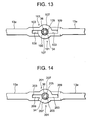
- FIG. 13 illustrates a structure in which the first skeleton members 7, 7 are connected to each other.
- Each of the engagement parts 101 has a first recessed part 103 elongated in the axial direction, a second recessed part 105 substantially in a half-round shape continuously formed by following the first recessed part 103, a first salient part 107 at the outer part of the second recessed part 105, and a second salient part 109 protruding at the and of the engagement part 101.
- the inside of the first recessed part 103 may be engaged, with the second salient part 109 of the engagement part 101 of the adjacent other first skeleton member 7.
- the form of the engagement parts 101 of the first skeleton member 7, provided at the respective ends of the four elongating parts 13a, is in the same shape.
- the form of the engagement parts 101 of the second skeleton members 9 is also in the same shape.
- the both second recessed parts 105, 105 form a hollow circle, with which the screw member 34 is engaged.
- FIG. 14 illustrates a structure in which the first skeleton members 7, 7 are connected to each other.
- engagement parts 201, 201 There are engagement parts 201, 201.
- Each of the engagement parts 201 has a first recessed part 203 elongated in the axial direction, a second recessed part 205 substantially in a half-round shape continuously formed by following the first recessed part 203, a first salient part 207 at the outer part of the second recessed part 205, and a second salient part 209 protruding at the and of the engagement part 201.
- the inside of the first recessed part 203 may be engaged, with the second salient part 209 of the engagement part 201 of the adjacent other first skeleton member 7.
- the form of the engagement parts 201 of the first skeleton member 7, provided at the respective ends of the four elongating parts 13a, is in the same shape.
- the form of the engagement parts 201 of the second skeleton members 9 is also in the same shape.
- the both second recessed parts 205, 205 form a hollow circle, with which the screw member 34 is engaged.
- FIG. 15 A fourth embodiment of the present invention will now be described with reference to Figs. 15 and 16.
- the second skeleton members 9 are fixed on the frame members 11, by the hexagon nut 75 and the fixing bolts 77, 79 (see Fig. 10).
- the fixing is done by rivets 301.
- the other structure is substantially the same as that of the first embodiment, so the identical reference numerals are given to the identical parts, and the detailed explanation will not be done here.
- the lattice panel comprises the first panels and the second panels.
- the lattice panel which comprises only the first panels.
Landscapes
- Engineering & Computer Science (AREA)
- Architecture (AREA)
- Civil Engineering (AREA)
- Structural Engineering (AREA)
- Physics & Mathematics (AREA)
- Electromagnetism (AREA)
- Joining Of Building Structures In Genera (AREA)
- Load-Bearing And Curtain Walls (AREA)
- Panels For Use In Building Construction (AREA)
Applications Claiming Priority (2)
| Application Number | Priority Date | Filing Date | Title |
|---|---|---|---|
| JP2003317043 | 2003-09-09 | ||
| JP2003317043A JP4155895B2 (ja) | 2003-09-09 | 2003-09-09 | ラティスパネルと建築物構築方法と建築物 |
Publications (1)
| Publication Number | Publication Date |
|---|---|
| EP1514973A2 true EP1514973A2 (fr) | 2005-03-16 |
Family
ID=34131967
Family Applications (1)
| Application Number | Title | Priority Date | Filing Date |
|---|---|---|---|
| EP04020870A Withdrawn EP1514973A2 (fr) | 2003-09-09 | 2004-09-02 | Panneau en treillis et construction de structures avec tels panneaux |
Country Status (4)
| Country | Link |
|---|---|
| US (1) | US7398627B2 (fr) |
| EP (1) | EP1514973A2 (fr) |
| JP (1) | JP4155895B2 (fr) |
| SG (2) | SG131117A1 (fr) |
Families Citing this family (5)
| Publication number | Priority date | Publication date | Assignee | Title |
|---|---|---|---|---|
| JP4779419B2 (ja) * | 2005-04-22 | 2011-09-28 | Sus株式会社 | 構造物 |
| US20080005967A1 (en) * | 2006-07-06 | 2008-01-10 | Johnson Douglas M | Stow-away pet barrier for use in a motor vehicle |
| IT1399804B1 (it) * | 2009-03-27 | 2013-05-03 | Fonderie A Doglione & C S P A | Moduli ed elementi d'arredo autoportanti in metallo, in particolare in lega di alluminio pressocolata, e procedimento per la loro eventuale finitura superficiale |
| US10143301B2 (en) * | 2011-01-21 | 2018-12-04 | Anita Brochette Summerville | Cabinet conversion panels |
| CA3228953A1 (fr) * | 2017-01-06 | 2018-07-12 | Valmont Industries, Inc. | Structure de support de bras transversal amelioree |
Family Cites Families (16)
| Publication number | Priority date | Publication date | Assignee | Title |
|---|---|---|---|---|
| US1641523A (en) * | 1925-07-06 | 1927-09-06 | Alvin L Bell | Grille frame |
| US2594864A (en) * | 1948-07-24 | 1952-04-29 | Hopkins & Buckland Ltd | Gate or the like |
| US3086629A (en) * | 1959-07-08 | 1963-04-23 | Blitzer Bud | Structural panels and elements thereof |
| US3155202A (en) * | 1960-02-29 | 1964-11-03 | Mission West Mfg Company | Architectural screen and building unit therefor |
| US3103264A (en) * | 1961-03-16 | 1963-09-10 | Anaconda American Brass Co | Extruded cross sections for architectural screens |
| US3302412A (en) * | 1964-06-29 | 1967-02-07 | William A Hunsucker | Interlocking sheet piles and method of installation |
| US3785098A (en) * | 1969-07-01 | 1974-01-15 | Schweitzer H E Ag | Composite panel structure |
| US4794744A (en) * | 1988-02-01 | 1989-01-03 | Young Holdings Ltd. Corp. | Wall construction for modular woven wire partition |
| JP2552782B2 (ja) * | 1991-10-07 | 1996-11-13 | 錬三 神野 | 格子枠組構造体 |
| US5241799A (en) * | 1991-12-10 | 1993-09-07 | Chicago Metallic Corporation | Open cell lay-in panel |
| JPH07324524A (ja) * | 1994-05-31 | 1995-12-12 | Takiron Co Ltd | ネットフェンス用パネル |
| JPH09302809A (ja) | 1996-05-09 | 1997-11-25 | Japan Idea Home:Kk | 壁パネルと開口部付き壁パネルを用いたパネル工法 |
| JPH11247337A (ja) | 1998-03-04 | 1999-09-14 | Misawa Homes Co Ltd | 壁パネルの割付構造及び壁パネルの割付設計方法 |
| JP3971836B2 (ja) | 1998-03-16 | 2007-09-05 | ミサワホーム株式会社 | 壁パネル |
| JP2001317156A (ja) | 2000-05-10 | 2001-11-16 | Higashi Nippon House Kk | 軸組パネル工法家屋建築用木質パネル |
| JP4008220B2 (ja) | 2001-09-28 | 2007-11-14 | Jfeシビル株式会社 | 外壁パネル、外壁パネル組立工法、および、パネル接合用のクリップ |
-
2003
- 2003-09-09 JP JP2003317043A patent/JP4155895B2/ja not_active Expired - Lifetime
-
2004
- 2004-08-30 SG SG200701783-3A patent/SG131117A1/en unknown
- 2004-08-30 SG SG200405613A patent/SG110192A1/en unknown
- 2004-09-02 EP EP04020870A patent/EP1514973A2/fr not_active Withdrawn
- 2004-09-09 US US10/936,488 patent/US7398627B2/en not_active Expired - Lifetime
Also Published As
| Publication number | Publication date |
|---|---|
| US20050050826A1 (en) | 2005-03-10 |
| US7398627B2 (en) | 2008-07-15 |
| SG110192A1 (en) | 2005-04-28 |
| JP2005083089A (ja) | 2005-03-31 |
| JP4155895B2 (ja) | 2008-09-24 |
| SG131117A1 (en) | 2007-04-26 |
Similar Documents
| Publication | Publication Date | Title |
|---|---|---|
| US8739493B2 (en) | Interlocking joint system for emergency structures | |
| US6708455B1 (en) | Polyhedral fabricated structure and method of constructing the same | |
| CN109610768B (zh) | 面板安装总成及方法 | |
| US7398627B2 (en) | Lattice panel and a lattice panel constructing method | |
| LT6370B (lt) | Sijos komponentai, skirti techniniam konstravimui, konstravimo rinkinys ir sijos komponentų sujungimo būdas | |
| WO2012081994A1 (fr) | Structure de verrouillage à système d'assemblage de construction modulaire associé | |
| US9097003B1 (en) | Saddle bracket assemblies | |
| WO2012099531A1 (fr) | Structure modulaire mobile multifonctionnelle | |
| KR101707529B1 (ko) | 유리 커튼 월 시스템 | |
| CN108933225A (zh) | 电池端子 | |
| KR100889360B1 (ko) | 커튼 월의 3차원 조립식 연결재의 시공방법 | |
| JPH10317547A (ja) | 壁パネルの上端結合構造 | |
| JP6484752B1 (ja) | 耐力パネル及び木造軸組建築物 | |
| JP2016108895A (ja) | パネルの連結構造 | |
| CN219931307U (zh) | 装配墙 | |
| JPH0451198Y2 (fr) | ||
| JP4811113B2 (ja) | 透明パネル装置 | |
| JP2972156B2 (ja) | 集合表示灯 | |
| KR0125993Y1 (ko) | 공기조화기용 케이스 | |
| CN219087063U (zh) | 一种组合式光伏组件 | |
| CN219973644U (zh) | 一种装饰板及吊顶 | |
| CN217841383U (zh) | 一种组合门结构 | |
| JP2006170310A (ja) | パネルを連結するためのクリップ及びパネル連結構造 | |
| CN211007196U (zh) | 一种组装式轻质隔墙板 | |
| JPH0792926A (ja) | 広告構造物 |
Legal Events
| Date | Code | Title | Description |
|---|---|---|---|
| PUAI | Public reference made under article 153(3) epc to a published international application that has entered the european phase |
Free format text: ORIGINAL CODE: 0009012 |
|
| AK | Designated contracting states |
Kind code of ref document: A2 Designated state(s): AT BE BG CH CY CZ DE DK EE ES FI FR GB GR HU IE IT LI LU MC NL PL PT RO SE SI SK TR |
|
| AX | Request for extension of the european patent |
Extension state: AL HR LT LV MK |
|
| STAA | Information on the status of an ep patent application or granted ep patent |
Free format text: STATUS: THE APPLICATION HAS BEEN WITHDRAWN |
|
| 18W | Application withdrawn |
Effective date: 20080812 |