EP1515020B1 - Brennkraftmaschine mit Abgasturbolader - Google Patents
Brennkraftmaschine mit Abgasturbolader Download PDFInfo
- Publication number
- EP1515020B1 EP1515020B1 EP04104369A EP04104369A EP1515020B1 EP 1515020 B1 EP1515020 B1 EP 1515020B1 EP 04104369 A EP04104369 A EP 04104369A EP 04104369 A EP04104369 A EP 04104369A EP 1515020 B1 EP1515020 B1 EP 1515020B1
- Authority
- EP
- European Patent Office
- Prior art keywords
- compressor
- internal combustion
- exhaust gas
- combustion engine
- norm
- Prior art date
- Legal status (The legal status is an assumption and is not a legal conclusion. Google has not performed a legal analysis and makes no representation as to the accuracy of the status listed.)
- Expired - Lifetime
Links
- 238000002485 combustion reaction Methods 0.000 title claims description 41
- 238000000034 method Methods 0.000 claims description 6
- 238000011144 upstream manufacturing Methods 0.000 claims description 5
- 238000002347 injection Methods 0.000 claims description 4
- 239000007924 injection Substances 0.000 claims description 4
- 239000002699 waste material Substances 0.000 claims 1
- 239000007789 gas Substances 0.000 description 51
- 238000006073 displacement reaction Methods 0.000 description 6
- 238000010586 diagram Methods 0.000 description 3
- 230000006835 compression Effects 0.000 description 2
- 238000007906 compression Methods 0.000 description 2
- 238000001816 cooling Methods 0.000 description 2
- 230000001419 dependent effect Effects 0.000 description 2
- 101100194363 Schizosaccharomyces pombe (strain 972 / ATCC 24843) res2 gene Proteins 0.000 description 1
- 238000010521 absorption reaction Methods 0.000 description 1
- 238000009825 accumulation Methods 0.000 description 1
- 239000003054 catalyst Substances 0.000 description 1
- 238000010438 heat treatment Methods 0.000 description 1
- 238000005086 pumping Methods 0.000 description 1
Images
Classifications
-
- F—MECHANICAL ENGINEERING; LIGHTING; HEATING; WEAPONS; BLASTING
- F02—COMBUSTION ENGINES; HOT-GAS OR COMBUSTION-PRODUCT ENGINE PLANTS
- F02D—CONTROLLING COMBUSTION ENGINES
- F02D41/00—Electrical control of supply of combustible mixture or its constituents
- F02D41/0002—Controlling intake air
- F02D41/0007—Controlling intake air for control of turbo-charged or super-charged engines
-
- F—MECHANICAL ENGINEERING; LIGHTING; HEATING; WEAPONS; BLASTING
- F02—COMBUSTION ENGINES; HOT-GAS OR COMBUSTION-PRODUCT ENGINE PLANTS
- F02B—INTERNAL-COMBUSTION PISTON ENGINES; COMBUSTION ENGINES IN GENERAL
- F02B37/00—Engines characterised by provision of pumps driven at least for part of the time by exhaust
-
- F—MECHANICAL ENGINEERING; LIGHTING; HEATING; WEAPONS; BLASTING
- F02—COMBUSTION ENGINES; HOT-GAS OR COMBUSTION-PRODUCT ENGINE PLANTS
- F02B—INTERNAL-COMBUSTION PISTON ENGINES; COMBUSTION ENGINES IN GENERAL
- F02B37/00—Engines characterised by provision of pumps driven at least for part of the time by exhaust
- F02B37/12—Control of the pumps
- F02B37/18—Control of the pumps by bypassing exhaust from the inlet to the outlet of turbine or to the atmosphere
-
- F—MECHANICAL ENGINEERING; LIGHTING; HEATING; WEAPONS; BLASTING
- F02—COMBUSTION ENGINES; HOT-GAS OR COMBUSTION-PRODUCT ENGINE PLANTS
- F02D—CONTROLLING COMBUSTION ENGINES
- F02D2200/00—Input parameters for engine control
- F02D2200/02—Input parameters for engine control the parameters being related to the engine
- F02D2200/04—Engine intake system parameters
- F02D2200/0406—Intake manifold pressure
-
- F—MECHANICAL ENGINEERING; LIGHTING; HEATING; WEAPONS; BLASTING
- F05—INDEXING SCHEMES RELATING TO ENGINES OR PUMPS IN VARIOUS SUBCLASSES OF CLASSES F01-F04
- F05B—INDEXING SCHEME RELATING TO WIND, SPRING, WEIGHT, INERTIA OR LIKE MOTORS, TO MACHINES OR ENGINES FOR LIQUIDS COVERED BY SUBCLASSES F03B, F03D AND F03G
- F05B2220/00—Application
- F05B2220/40—Application in turbochargers
-
- Y—GENERAL TAGGING OF NEW TECHNOLOGICAL DEVELOPMENTS; GENERAL TAGGING OF CROSS-SECTIONAL TECHNOLOGIES SPANNING OVER SEVERAL SECTIONS OF THE IPC; TECHNICAL SUBJECTS COVERED BY FORMER USPC CROSS-REFERENCE ART COLLECTIONS [XRACs] AND DIGESTS
- Y02—TECHNOLOGIES OR APPLICATIONS FOR MITIGATION OR ADAPTATION AGAINST CLIMATE CHANGE
- Y02T—CLIMATE CHANGE MITIGATION TECHNOLOGIES RELATED TO TRANSPORTATION
- Y02T10/00—Road transport of goods or passengers
- Y02T10/10—Internal combustion engine [ICE] based vehicles
- Y02T10/12—Improving ICE efficiencies
Definitions
- Turbocharged engines are primarily used to increase the displacement specific peak power. This is accompanied by the use of relatively large-volume turbocharger with turbine or compressor, which achieve a high degree of supercharging at high speeds and exhaust gas mass flows, but at low speeds and exhaust gas mass flows have a sluggish response to load requirements (so-called turbo lag). Many drivers find the steady-state torque characteristics of a supercharged direct-injection diesel engine pleasant, but the turbo lag is there as well.
- a valve device for controlling an exhaust gas turbocharger turbine for internal combustion engines with at least two exhaust gas flows is known.
- a valve device is provided in an exhaust system and has two valve elements. By the first valve element, an opening between the one exhaust gas flow and the other exhaust gas flow is closable. Through the second valve, an opening between the one exhaust gas flow and a connecting line can be closed.
- the arrangement of the second valve element of the valve device between the one exhaust gas flow and the connecting line it is possible to open the connecting line at a certain pressure, which in addition to the accumulation charging of the turbine, which is achieved by opening the first valve element, a partial flow of the exhaust gas is guided past the turbine.
- the invention has for its object to provide a exhaust-gas-charged internal combustion engine with good response even at low speeds available.
- the boost pressure of the turbocharger for example by opening a wastegate of the exhaust gas turbocharger is lowered.
- the stroke volume of the internal combustion engine is 700 cm 3 to 5,100 cm 3 , in particular 950 cm 3 to 2250 cm 3 , preferably 990 cm 3 to 1,800 cm 3 and the rated speed of the internal combustion engine 4,800 rev / min to 6,200 rev / min, in particular 5,200 rev / min to 5,700 rpm.
- the combination of exhaust-gas turbocharger and internal combustion engine is selected such that it has a relatively low compressor pressure ratio, in particular in the upper engine speed range in comparison to conventionally supercharged engines.
- the response of the exhaust gas turbocharger is improved at low speeds, since the boost pressure is raised in the range of low engine speeds of the internal combustion engine.
- the boost pressure In the range of medium to high engine speeds of the boost pressure by appropriate selection of the components and possibly by a correspondingly executed control, for example by means of a wastegate, the boost pressure additionally lowered significantly.
- the maximum airflow to be managed by the compressor or the exhaust gas mass flow to be handled by the turbine can be significantly reduced, whereas in a conventional design the charge pressure is kept virtually constant over a wide speed range up to the rated speed or even increases. In the conventional design, this leads to a significant increase in engine performance and thus the combustion air and the exhaust gas mass flow.
- the turbomachinery ie compressors and turbines, must be designed to handle high mass flows as large units, in the design according to the invention small geometric dimensions of turbine and compressor are sufficient.
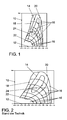
- FIG. 1 shows a compressor map for a compressor of an exhaust gas turbocharger for a combination of exhaust gas turbocharger and internal combustion engine according to the invention.
- FIG. 2 shows a compressor map for a compressor of an exhaust gas turbocharger for a conventional combination of exhaust gas turbocharger and internal combustion engine.
- p Compressor pressure ratio p 2 ⁇ t p 1 ⁇ t where p 1t is a pressure before the compressor and p 2t is a pressure downstream of the compressor.
- V NORM a standardized fresh air volume flow
- V Norm takes into account a design of the exhaust gas turbocharger with respect to the characteristic quantities n nominal and V H of the internal combustion engine.
- Denoted by 14 are lines of constant maximum efficiency of the compressor, 16 being lines of constant value for n V / n Vmax , where n V is a speed of the compressor of the exhaust gas turbocharger and n Vmax is a predetermined maximum speed of the compressor of the exhaust gas turbocharger is, and at 18 is a surge limit, below which the compressor of the exhaust gas turbocharger can not be operated without being damaged.
- a line 24 indicates a full-load operating line of the internal combustion engine.
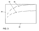
- FIG. 3 shows a turbine characteristic diagram for a turbine of an exhaust gas turbocharger.
- a reduced turbine mass flow mredT On the vertical axis 26 is a reduced turbine mass flow mredT and on the horizontal axis 28, a relaxation ratio of the turbine p 3t / p 4t is plotted, where p 3t is a pressure upstream of the turbine of the exhaust gas turbocharger and p 4t is a pressure downstream of the turbine of the exhaust gas turbocharger.
- At 30 is a course of mredT on the expansion ratio for a conventional design of the exhaust gas turbocharger according to the compressor map of Fig. 2 and 32 is a course of mredT on the relaxation ratio for an inventive design of the exhaust gas turbocharger according to the compressor map of Fig. 1 plotted.
- a corresponding control for example a wastegate control
- the inventive design of the exhaust gas turbocharger with respect to the internal combustion engine achieves the following: A higher turbine power at low engine speeds; a lower mass moment of inertia of the rotor of the exhaust gas turbocharger; lower bearing friction losses due to a smaller shaft diameter; lower thermal inertia of the turbine housing; less heat loss in the turbine due to smaller surface area; smaller size; an increase in steady state torque at low engine speeds over conventional turbo engines; a much better response of the turbocharger with good dynamic torque build-up (turbo lag reduction); an improved heating behavior of a catalyst disposed in the exhaust line downstream of the exhaust gas turbocharger; a smaller footprint and a lower weight.
- an exhaust gas turbocharger designed according to the invention is combined with a direct-injection gasoline engine.
- This engine is preferably operated at least in the idling speed range ( ⁇ 1,500 rpm, ⁇ 1.5 bar) in the stratified operation mode.
- the engine preferably has four valves per cylinder.
- the internal combustion engine according to the invention has for example a maximum liter power of 50 kW to 70 kW, optimally from 55 kW to 65 kW, in the rated speed band of preferably 4,800 rpm to 6,200 rpm, optimally 5,200 rpm to 5,700 rpm.
Landscapes
- Engineering & Computer Science (AREA)
- Chemical & Material Sciences (AREA)
- Combustion & Propulsion (AREA)
- Mechanical Engineering (AREA)
- General Engineering & Computer Science (AREA)
- Supercharger (AREA)
Description
- Die Erfindung betrifft eine Brennkraftmaschine, insbesondere einen direkteinspritzenden Dieselmotor oder Ottomotor, insbesondere eines Kraftfahrzeuges, mit einem Abgasturbolader, welcher einen Verdichter und eine Turbine aufweist, wobei die Brennkraftmaschine eine vorbestimmte Nenndrehzahl nNenn sowie ein vorbestimmtes Hubvolumen VH aufweist, wobei ferner ein Verdichterdruckverhältnis pVerdichterdruckerhältnis des Verdichters des Abgasturboladers definiert ist als der Quotient eines Druckes p2t nach dem Verdichter zu einem Druck p1t vor dem Verdichter gemäß der Formel


- Turbomotoren werden primär zur Steigerung der hubraumspezifischen Spitzenleistung eingesetzt. Damit einher geht die Verwendung vergleichsweise großvolumiger Turbolader mit Turbine bzw. Verdichter, die bei hohen Drehzahlen und Abgasmassenströmen einen hohen Aufladegrad erreichen, aber bei kleinen Drehzahlen und Abgasmassenströmen ein träges Ansprechverhalten bei Lastanforderung aufweisen (sogen. Turboloch). Von vielen Fahrern wird die stationäre Drehmomentcharakteristik eines aufgeladenen direkteinspritzenden Dieselmotors als angenehm empfunden, das Turboloch ist jedoch auch dort vorhanden.
- Aus der
DE 695 19 306 T2 ist es zur Reduzierung des Turboloches bekannt, eine Hilfsverbrennungskammer vorzusehen, welche Gase zum Antrieb der Turbine des Turboladers erzeugt. - Aus der
DE 198 26 355 A1 ist eine Vorrichtung zur Steuerung einer Abgasturboladerturbine für Brennkraftmaschinen mit wenigstens zwei Abgasfluten bekannt. Eine Ventileinrichtung ist in einem Abgassystem vorgesehen und weist zwei Ventilelemente auf. Durch das erste Ventilelement ist eine Öffnung zwischen der einen Abgasflut und der anderen Abgasflut verschließbar. Durch das zweite Ventil ist eine Öffnung zwischen der einen Abgasflut und einer Verbindungsleitung verschließbar. Durch die Anordnung des zweiten Ventilelementes der Ventileinrichtung zwischen der einen Abgasflut und der Verbindungsleitung ist es möglich, die Verbindungsleitung bei einem bestimmten Druck zu öffnen, wodurch zusätzlich zu der Stauaufladung der Turbine, welche durch das Öffnen des ersten Ventilelementes erzielt wird, ein Teilstrom des Abgases an der Turbine vorbeigeleitet wird. Dadurch wird einem Anstieg der Ladungswechselarbeit bzw. Gaswechselarbeit entgegengewirkt, weil der Durchsatz von Abgas in der zu der Turbine führenden Abgasleitung begrenzt wird. Die Schluckfähigkeit der Turbine wird stark erhöht und es kann eine Turbine mit sehr kleinem Querschnitt verwendet werden, was bei niedrigen Motordrehzahlen durch die erzielbaren höheren Ladedrücke eine bessere Turbinenleistung zur Folge hat. Die Turbine kann dadurch so ausgelegt werden, dass sie im unteren Drehzahlbereich noch ein möglichst akzeptables Ansprechverhalten aufweist und somit ein höchstmögliches Ladedruckniveau und eine damit verbundene hohe Leistung der Turbine erbracht wird. - Aus der
DE 197 06 859 A1 ist ein Verfahren und eine Vorrichtung zur Steigerung des Wirkungsgrades von aufgeladenen Ottomotoren über eine Erhöhung der Grundverdichtung bekannt. Mittels einer zwei- oder mehrstufigen Ladeluftverdichtung und mehrstufiger Ladeluftkühlung kann der Ladedruck über das Niveau bisheriger aufgeladener Brennkraftmaschinen mit einstufiger Ladeluftkühlung angehoben werden. - Der Erfindung liegt die Aufgabe zugrunde, eine abgasturboaufgeladene Brennkraftmaschine mit gutem Ansprechverhalten auch bei kleinen Drehzahlen zur Verfügung zu stellen.
- Diese Aufgabe wird erfindungsgemäß durch eine Brennkraftmaschine der o.g. Art mit den in Anspruch 1 gekennzeichneten Merkmalen sowie durch ein Verfahren der o.g. Art mit den in Anspruch 6 gekennzeichneten Merkmalen gelöst. Vorteilhafte Ausgestaltungen der Erfindung sind in den abhängigen Ansprüchen angegeben.
- Dazu ist es bei einer Brennkraftmaschine der o.g. Art erfindungsgemäß vorgesehen, dass der Abgasturbolader derart ausgebildet ist, dass eine ein Verdichterkennfeld, in dem das Verdichterdruckverhältnis pVerdichterdruckerhältnis über dem normierten Frischluftvolumenstrom VNORM aufgetragen ist, begrenzende Funktion des Verdichterdruckverhältnisses pVerdichterdruckernältnis in Abhängigkeit von dem normierten Frischluftvolumenstrom VNORM für eine konstante Verdichterdrehzahl nV = nVmax, wobei nV eine Drehzahl des Verdichters des Abgasturboladers und nVmax eine vorbestimmte maximale Drehzahl des Verdichters des Abgasturboladers ist, einen Wert pVerdichterdruckerhältnis (VNORM) =1 bei einem Wert VNORM<0,7, insbesondere VNORM<0,65, vorzugsweise VNORM<0,60, erreicht.
- Ferner ist es bei einem Verfahren der o.g. Art erfindungsgemäß vorgesehen, dass in einem mittleren bis oberen Drehzahlbereich entsprechend VNorm > 0,35 der Ladedruck des Turboladers, beispielsweise durch Öffnen eines Wastegates des Abgasturboladers, abgesenkt wird.
- Dies hat den Vorteil, dass eine Auslegung des Abgasturboladers relativ zu den wesentlichen Kenndaten der Brennkraftmaschine, nämlich Hubraum und Nennrehzahl, derart getroffen ist, dass in einem oberen Drehzahlbereich ein relativ geringes Verdichterdruckverhältnis vorliegt, während ein Ladedruck bei niedrigen Drehzahlen angehoben ist. Gleichzeitig wird eine Verbrauchsminderung bei besserer Fahrleistung erzielt.
- Dadurch, dass der Abgasturbolader derart ausgebildet ist, dass eine Funktionenschar pVerdichterdruckerhältnis (VNORM) für

- Beispielsweise beträgt das Hubvolumen der Brennkraftmaschine 700 cm3 bis 5.100 cm3, insbesondere 950 cm3 bis 2250 cm3, vorzugsweise 990 cm3 bis 1.800 cm3 und die Nenndrehzahl der Brennkraftmaschine 4.800 U/min bis 6.200 U/min, insbesondere 5.200 U/min bis 5.700 U/min.
- Weitere Merkmale, Vorteile und vorteilhafte Ausgestaltungen der Erfindung ergeben sich aus den abhängigen Ansprüchen, sowie aus der nachstehenden Beschreibung der Erfindung anhand der beigefügten Zeichnungen. Diese zeigen in
- Fig. 1
- ein Verdichterkennfeld für einen Verdichter eines Abgasturboladers einer erfindungsgemäßen Brennkraftmaschine,
- Fig. 2
- ein Verdichterkennfeld für einen Verdichter eines Abgasturboladers einer herkömmlichen Brennkraftmaschine und
- Fig. 3
- Turbinenkennfelder für eine Turbine eines Abgasturboladers einer erfindungsgemäßen und einer herkömmlichen Brennkraftmaschine.
- Erfindungsgemäß ist die Kombination von Abgasturbolader und Brennkraftmaschine derart gewählt, dass diese insbesondere im oberen Motordrehzahlbereich im Vergleich zu herkömmlich aufgeladenen Motoren ein relativ geringes Verdichterdruckverhältnis aufweist. Das Ansprechverhalten des Abgasturboladers ist bei niedrigen Drehzahlen verbessert, da der Ladedruck im Bereich niedriger Motordrehzahlen der Brennkraftmaschine angehoben ist. Im Bereich von mittleren bis hohen Motordrehzahlen wird der Ladedruck durch geeignete Auswahl der Komponenten und ggf. durch eine entsprechend ausgeführte Regelung, beispielsweise mittels eines Wastegates, der Ladedruck zusätzlich signifikant abgesenkt. Dadurch kann der maximal vom Verdichter zu bewältigende Luftstrom bzw. der maximal von der Turbine zu bewältigende Abgasmassenstrom deutlich reduziert werden, wogegen bei einer herkömmlichen Auslegung der Ladedruck über einen weiten Drehzahlbereich bis zur Nenndrehzahl nahezu konstant gehalten wird oder sogar ansteigt. Bei der konventionellen Auslegung führt dies zu einer deutlichen Anhebung der Motorleistung und damit des Verbrennungsluft- und des Abgasmassenstromes. Während daher herkömmlicherweise die Turbomaschinen, d.h. Verdichter und Turbinen, zur Bewältigung hoher Massenströme als große Einheiten ausgebildet sein müssen, genügen bei der erfindungsgemäßen Auslegung kleine geometrische Abmessungen von Turbine und Verdichter.
- Fig. 1 zeigt ein Verdichterkennfeld für einen Verdichter eines Abgasturboladers für eine erfindungsgemäße Kombination von Abgasturbolader und Brennkraftmaschine. Fig. 2 zeigt ein Verdichterkennfeld für einen Verdichter eines Abgasturboladers für eine herkömmliche Kombination von Abgasturbolader und Brennkraftmaschine. Hierbei ist auf der vertikalen Achse 10 ein Verdichterdruckverhältnis pVerdicherdruckverhältnis aufgetragen, welches gemäß der Formel


- Im Vergleich der Verdichterkennfelder gemäß Fig. 1 und Fig. 2 ist ersichtlich, dass sich bei dem Verdichterkennfeld gemäß Fig. 1 durch Absenkung des Ladedruckes im oberen Drehzahlbereich der durchzusetzende Volumenstrom bei gleichem Hubraum und gleicher Nenndrehzahl deutlich verringert, so dass ein kleinerer Verdichter eingesetzt werden kann. Die Pumpgrenze 18 des kleineren Verdichters liegt bei kleineren Volumenströmen, wodurch ein größerer Ladedruck und damit ein größeres Motormoment bei kleiner Motordrehzahl erreichbar sind. Das Verdichterkennfeld gemäß Fig. 1 ist schmäler. Der Verlauf gemäß der Funktion pVer dichterdruckverhältnis(VNorm) für einen Wert nV/nVmax = 1 gemäß Linie 20 begrenzt das Verdichterkennfeld in Richtung höhere Werte für VNorm. Wie sich unmittelbar im Vergleich der Verdichterkennfelder gemäß Fig. 1 und Fig. 2 ergibt, befindet sich diese Grenzlinie 20 bei Fig. 1 bei deutlich niedrigeren Werten für VNorm.
- Fig. 3 zeigt ein Turbinenkennfeld für eine Turbine eines Abgasturboladers. Auf der vertikalen Achse 26 ist ein reduzierter Turbinenmassenstrom mredT und auf der horizontalen Achse 28 ist ein Entspannungsverhältnis der Turbine p3t/p4t aufgetragen, wobei p3t ein Druck stromauf der Turbine des Abgasturboladers und p4t ein Druck stromab der Turbine des Abgasturboladers ist. Bei 30 ist ein Verlauf von mredT über das Entspannungsverhältnis für eine herkömmliche Auslegung des Abgasturboladers gemäß Verdichterkennfeld von Fig. 2 und bei 32 ist ein Verlauf von mredT über das Entspannungsverhältnis für eine erfindungsgemäße Auslegung des Abgasturboladers gemäß Verdichterkennfeld von Fig. 1 aufgetragen. Hieraus ist ersichtlich, dass bei gleichem Entspannungsverhältnis auch der Abgasmassenstrom 26 bei einer erfindungsgemäßen Turbinenauslegung gemäß Linie 32 geringer ist als bei einer herkömmlichen Auslegung gemäß Linie 30. Umgekehrt erreicht die kleinere Turbine der erfindungsgemäßen Auslegung gemäß Linie 32 bei gleicher Motordrehzahl einen höheren Abgasgegendruck, so dass die Leistung der Turbine im unteren Bereich der Motordrehzahl steigt, wie aus Fig. 1, Linie 24 ersichtlich ist. Ein Wastegate der Turbine kann eine überschüssige Abgasmenge trotz der geringen Abmessungen auch im oberen Drehzahlbereich an der Turbine vorbeiführen, da im Vergleich zum konventionellen Turbomotor weniger Abgasstrom anfällt.
- Optional wird, wie unmittelbar von der Volllastkennlinie 24 in Fig. 1 ersichtlich, durch eine entsprechende Regelung, beispielsweise eine Wastegate-Regelung, der Ladedruck von mittleren bis zu hohen Motordrehzahlen, entsprechend Werten von VNorm von 0,35 bis 0,55, signifikant abgesenkt.
- Durch die erfindungsgemäße Auslegung des Abgasturboladers in Bezug auf die Brennkraftmaschine wird folgendes erreicht: Eine höhere Turbinenleistung bei kleinen Motordrehzahlen; ein geringeres Massenträgheitsmoment des Rotors des Abgasturboladers; geringere Lagerreibungsverluste aufgrund eines kleineren Wellendurchmessers; geringere thermische Trägheit des Turbinengehäuses; weniger Wärmeverluste in der Turbine wegen kleinerer Oberfläche; geringere Baugröße; eine Anhebung des stationären Drehmomentes bei niedrigen Motordrehzahlen gegenüber herkömmlichen Turbomotoren; ein wesentlich besseres Ansprechverhalten des Abgasturboladers mit gutem dynamischen Drehmomentaufbau (Verringerung des Turboloches); ein verbessertes Aufheizverhalten eines im Abgasstrang stromab des Abgasturboladers angeordneten Katalysators; ein geringerer Platzbedarf und ein geringeres Gewicht.
- Mit der erfindungsgemäßen Auslegung des Abgasturboladers in Bezug auf die Brennkraftmaschine werden beispielsweise folgende stationäre Mitteldrücke erreicht bzw. überschritten:
- >10,5 bar, insbesondere >11 bar, bevorzugt >11,5 bar, optimal >12 bar bei einer Motordrehzahl von 1.000 U/min; und/oder
- >15 bar, insbesondere >15,5 bar, bevorzugt >16 bar, optimal >16,5 bar bei einer Motordrehzahl von 1.350 U/min; und/oder
- >15,5 bar, insbesondere >16 bar, bevorzugt >16,5 bar, optimal >17 bar bei einer Motordrehzahl von 1.500 U/min.
- Dynamisch. d.h. bei einer dem Kleinlastbetrieb folgenden Volllast-Wunschvorgabe, wird folgender Mitteldruckverlauf erreicht bzw. überschritten: Motordrehzahl konstant 1.320 U/min, stationärer Betrieb 3,5 bar, diesem folgend die Volllast-Wunschvorgabe:
- Nach 250 ms >5 bar, insbesondere >5,5 bar, bevorzugt >6 bar, optimal >6,5 bar; und/oder
- nach 500 ms >6 bar, insbesondere >6,5 bar, bevorzugt >7 bar, optimal >7,5 bar; und/oder
- nach 1.000 ms >9 bar, insbesondere >9,5 bar, bevorzugt >10 bar, optimal >10,5 bar (im Stand der Technik werden hier nur 5,5 bis 7 bar erreicht).
- Bevorzugt wird ein erfindungsgemäß ausgelegter Abgasturbolader mit einem direkteinspritzenden Ottomotor kombiniert. Dieser Motor wird vorzugsweise zumindest im leerlaufnahen Drehzahlbereich (<1.500 U/min, <1,5 bar) im Schichtbetriebsmodus betrieben. Der Motor weist bevorzugt vier Ventile pro Zylinder auf.
- Die erfindungsgemäße Brennkraftmaschine hat beispielsweise eine maximale Literleistung von 50 kW bis 70 kW, optimal von 55 kW bis 65 kW, im Nenndrehzahlband von vorzugsweise 4.800 U/min bis 6.200 U/min, optimal 5.200 U/min bis 5.700 U/min.
Claims (7)
- Brennkraftmaschine, insbesondere einen direkteinspritzenden Dieselmotor oder Ottomotor, insbesondere eines Kraftfahrzeuges, mit einem Abgasturbolader, welcher einen Verdichter und eine Turbine aufweist, wobei die Brennkraftmaschine eine vorbestimmte Nenndrehzahl nNenn sowie ein vorbestimmtes Hubvolumen VH aufweist, wobei ferner ein Verdichterdruckverhältnis pVerdichterdruckerhältnis (10) des Verdichters des Abgasturboladers definiert ist als der Quotient eines Druckes p2t nach dem Verdichter zu einem Druck p1t vor dem Verdichter gemäß der Formel


dadurch gekennzeichnet,
dass der Abgasturbolader derart ausgebildet ist, dass eine ein Verdichterkennfeld, in dem das Verdichterdruckverhältnis pVerdichterdruckerhältnis (10) über dem normierten Frischluftvolumenstrom VNORM (12) aufgetragen ist, begrenzende Funktion (20) des Verdichterdruckverhältnisses pVerdichterdruckerhältnis (10) in Abhängigkeit von dem normierten Frischluftvolumenstrom VNORM (12) für eine konstante Verdichterdrehzahl nV= nVmax, wobei nV eine Drehzahl des Verdichters des Abgasturboladers und nVmax eine vorbestimmte maximale Drehzahl des Verdichters des Abgasturboladers ist, einen Wert pVerdichterdruckerhältnis (VNORM) =1 bei einem Wert VNORM<0,7 erreicht. - Brennkraftmaschine nach Anspruch 1, dadurch gekennzeichnet, dass der Abgasturbolader derart ausgebildet ist, dass die Funktion pVerdichterdruckerhältnis (VNORM) für nV=nVmax den Wert 1 bei VNORM<0,65, insbesondere bei VNORM<0,60, erreicht.
- Brennkraftmaschine nach Anspruch 1 oder 2, dadurch gekennzeichnet, dass der Abgasturbolader derart ausgebildet ist, dass eine Funktionenschar pVerdichterdruckerhältnis(VNORM) für

- Brennkraftmaschine nach wenigstens einem der vorhergehenden Ansprüche, dadurch gekennzeichnet, dass das Hubvolumen der Brennkraftmaschine 700 cm3 bis 5.100 cm3, insbesondere 950 cm3 bis 2.250 cm3, vorzugsweise 990 cm3 bis 1.800 cm3 beträgt.
- Brennkraftmaschine nach wenigstens einem der vorhergehenden Ansprüche, dadurch gekennzeichnet, dass die Nenndrehzahl der Brennkraftmaschine 4.800 U/min bis 6.200 U/min, insbesondere 5.200 U/min bis 5.700 U/min beträgt.
- Verfahren zum Betreiben einer Brennkraftmaschine, welche gemäß wenigstens einem der vorhergehenden Ansprüche ausgebildet ist,
dadurch gekennzeichnet,
dass in einem mittleren bis oberen Drehzahlbereich entsprechend VNorm > 0,35 der Ladedruck des Turboladers abgesenkt wird. - Verfahren nach Anspruch 6, dadurch gekennzeichnet, dass der Ladedruck durch Öffnen eines Wastgates des Abgasturboladers abgesenkt wird.
Applications Claiming Priority (2)
| Application Number | Priority Date | Filing Date | Title |
|---|---|---|---|
| DE10342018 | 2003-09-11 | ||
| DE10342018A DE10342018A1 (de) | 2003-09-11 | 2003-09-11 | Brennkraftmaschine mit Abgasturbolader |
Publications (2)
| Publication Number | Publication Date |
|---|---|
| EP1515020A1 EP1515020A1 (de) | 2005-03-16 |
| EP1515020B1 true EP1515020B1 (de) | 2007-09-26 |
Family
ID=34129761
Family Applications (1)
| Application Number | Title | Priority Date | Filing Date |
|---|---|---|---|
| EP04104369A Expired - Lifetime EP1515020B1 (de) | 2003-09-11 | 2004-09-10 | Brennkraftmaschine mit Abgasturbolader |
Country Status (4)
| Country | Link |
|---|---|
| EP (1) | EP1515020B1 (de) |
| AT (1) | ATE374309T1 (de) |
| DE (2) | DE10342018A1 (de) |
| WO (1) | WO2006034728A1 (de) |
Family Cites Families (4)
| Publication number | Priority date | Publication date | Assignee | Title |
|---|---|---|---|---|
| US5025629A (en) * | 1989-03-20 | 1991-06-25 | Woollenweber William E | High pressure ratio turbocharger |
| DE10007669B4 (de) * | 2000-02-19 | 2005-09-15 | Daimlerchrysler Ag | Verfahren zur Regelung eines Verdichters, insbesondere eines Verdichters im Ansaugtrakt einer Brennkraftmaschine |
| DE10043760B4 (de) * | 2000-09-05 | 2007-09-20 | Siemens Ag | Begrenzer für ein Zusatzgerät einer Brennkraftmaschine sowie zugehöriges Verfahren |
| JP3873742B2 (ja) * | 2001-12-28 | 2007-01-24 | いすゞ自動車株式会社 | 可変容量ターボチャージャの制御装置 |
-
2003
- 2003-09-11 DE DE10342018A patent/DE10342018A1/de not_active Withdrawn
-
2004
- 2004-09-10 DE DE502004005067T patent/DE502004005067D1/de not_active Expired - Lifetime
- 2004-09-10 EP EP04104369A patent/EP1515020B1/de not_active Expired - Lifetime
- 2004-09-10 AT AT04104369T patent/ATE374309T1/de not_active IP Right Cessation
- 2004-09-29 WO PCT/EP2004/010897 patent/WO2006034728A1/de not_active Ceased
Also Published As
| Publication number | Publication date |
|---|---|
| DE10342018A1 (de) | 2005-06-23 |
| EP1515020A1 (de) | 2005-03-16 |
| DE502004005067D1 (de) | 2007-11-08 |
| WO2006034728A1 (de) | 2006-04-06 |
| ATE374309T1 (de) | 2007-10-15 |
Similar Documents
| Publication | Publication Date | Title |
|---|---|---|
| WO2003083275A1 (de) | Variabler abgasturbolader | |
| EP0735253A2 (de) | Verfahren und Vorrichtung zur Registeraufladung einer Brennkraftmaschine | |
| EP1388654B1 (de) | Aufgeladene Brennkraftmaschine | |
| DE102004003378B4 (de) | Regelungs- und Steuerungsvorrichtung und Regelungs- und Steuerungsverfahren für einen mehrstufigen Turbolader | |
| DE202015102239U1 (de) | Abgasturboaufgeladene Brennkraftmaschine mit Teilabschaltung und parallel angeordneten Turbinen | |
| EP0091139B2 (de) | Abgasturbolader an aufgeladenem Dieselmotor | |
| EP1788220B1 (de) | Verfahren zur Steuerung eines Turboladers mit turbinenseitiger Ladedruck-Regelung und einem Umluftventil | |
| DE102014221331A1 (de) | Verfahren zum Betreiben einer aufgeladenen Brennkraftmaschine und Brennkraftmaschine zur Durchführung eines derartigen Verfahrens umfassend eine variable Turbine | |
| EP1640595A1 (de) | Aufgeladene Brennkraftmaschine und Verfahren zum Betreiben einer derartigen Brennkraftmaschine | |
| DE102014211127B4 (de) | Aufgeladene Brennkraftmaschine mit in Reihe angeordneten Abgasturboladern und Abgasrückführung und Verfahren zum Betreiben einer derartigen Brennkraftmaschine | |
| EP2058485B1 (de) | Aufgeladene Brennkraftmaschine und Verfahren zum Betreiben einer derartigen Brennkraftmaschine | |
| EP1515020B1 (de) | Brennkraftmaschine mit Abgasturbolader | |
| DE102015207539A1 (de) | Abgasturboaufgeladene Brennkraftmaschine mit Teilabschaltung und parallel angeordneten Turbinen und Verfahren zum Betreiben einer derartigen Brennkraftmaschine | |
| DE102016200918B3 (de) | Aufgeladene Brennkraftmaschine mit Verdichter und Verfahren zum Betreiben einer derartigen Brennkraftmaschine | |
| DE29723421U1 (de) | Aufladeeinrichtung eines Verbrennungsmotors | |
| DE202014104419U1 (de) | Aufgeladene Brennkraftmaschine mit in Reihe angeordneten Abgasturboladern | |
| DE102014218345A1 (de) | Aufgeladene Brennkraftmaschine mit in Reihe angeordneten Abgasturboladern | |
| DE202015103551U1 (de) | Abgasturboaufgeladene Brennkraftmaschine mit Teilabschaltung und Zusatzverdichter | |
| EP1626169A1 (de) | Regelungsvorrichtung für einen Verbrennungsmotor | |
| EP2058486B1 (de) | Aufgeladene Brennkraftmaschine und Verfahren zum Betreiben einer derartigen Brennkraftmaschine | |
| DE202014102710U1 (de) | Aufgeladene Brennkraftmaschine mit in Reihe angeordneten Abgasturboladern | |
| DE202015101927U1 (de) | Aufgeladene Brennkraftmaschine mit Kompressor und Elektromaschine | |
| DE102015205676B4 (de) | Aufgeladene Brennkraftmaschine mit Abgasturbolader und Zusatzverdichter und Verfahren zum Betreiben einer derartigen Brennkraftmaschine | |
| DE102015211228A1 (de) | Abgasturboaufgeladene Brennkraftmaschine mit Teilabschaltung und Zusatzverdichter und Verfahren zum Betreiben einer derartigen Brennkraftmaschine | |
| DE102014220680A1 (de) | Brennkraftmaschine mit Mixed-Flow-Turbine umfassend eine Leiteinrichtung |
Legal Events
| Date | Code | Title | Description |
|---|---|---|---|
| PUAI | Public reference made under article 153(3) epc to a published international application that has entered the european phase |
Free format text: ORIGINAL CODE: 0009012 |
|
| AK | Designated contracting states |
Kind code of ref document: A1 Designated state(s): AT BE BG CH CY CZ DE DK EE ES FI FR GB GR HU IE IT LI LU MC NL PL PT RO SE SI SK TR |
|
| AX | Request for extension of the european patent |
Extension state: AL HR LT LV MK |
|
| RIN1 | Information on inventor provided before grant (corrected) |
Inventor name: POTT, EKKEHARD Inventor name: THEOBALD, JOERG Inventor name: STIEBELS, BERND Inventor name: EBUS, FEITSE Inventor name: HAGELSTEIN, DIRK Inventor name: KLOFT, MANFRED |
|
| 17P | Request for examination filed |
Effective date: 20050916 |
|
| AKX | Designation fees paid |
Designated state(s): AT BE BG CH CY CZ DE DK EE ES FI FR GB GR HU IE IT LI LU MC NL PL PT RO SE SI SK TR |
|
| GRAP | Despatch of communication of intention to grant a patent |
Free format text: ORIGINAL CODE: EPIDOSNIGR1 |
|
| GRAS | Grant fee paid |
Free format text: ORIGINAL CODE: EPIDOSNIGR3 |
|
| GRAA | (expected) grant |
Free format text: ORIGINAL CODE: 0009210 |
|
| AK | Designated contracting states |
Kind code of ref document: B1 Designated state(s): AT BE BG CH CY CZ DE DK EE ES FI FR GB GR HU IE IT LI LU MC NL PL PT RO SE SI SK TR |
|
| REG | Reference to a national code |
Ref country code: GB Ref legal event code: FG4D Free format text: NOT ENGLISH |
|
| REG | Reference to a national code |
Ref country code: CH Ref legal event code: EP |
|
| REF | Corresponds to: |
Ref document number: 502004005067 Country of ref document: DE Date of ref document: 20071108 Kind code of ref document: P |
|
| REG | Reference to a national code |
Ref country code: IE Ref legal event code: FG4D Free format text: LANGUAGE OF EP DOCUMENT: GERMAN |
|
| PG25 | Lapsed in a contracting state [announced via postgrant information from national office to epo] |
Ref country code: FI Free format text: LAPSE BECAUSE OF FAILURE TO SUBMIT A TRANSLATION OF THE DESCRIPTION OR TO PAY THE FEE WITHIN THE PRESCRIBED TIME-LIMIT Effective date: 20070926 |
|
| ET | Fr: translation filed | ||
| PG25 | Lapsed in a contracting state [announced via postgrant information from national office to epo] |
Ref country code: PL Free format text: LAPSE BECAUSE OF FAILURE TO SUBMIT A TRANSLATION OF THE DESCRIPTION OR TO PAY THE FEE WITHIN THE PRESCRIBED TIME-LIMIT Effective date: 20070926 |
|
| NLV1 | Nl: lapsed or annulled due to failure to fulfill the requirements of art. 29p and 29m of the patents act | ||
| GBV | Gb: ep patent (uk) treated as always having been void in accordance with gb section 77(7)/1977 [no translation filed] | ||
| PG25 | Lapsed in a contracting state [announced via postgrant information from national office to epo] |
Ref country code: NL Free format text: LAPSE BECAUSE OF FAILURE TO SUBMIT A TRANSLATION OF THE DESCRIPTION OR TO PAY THE FEE WITHIN THE PRESCRIBED TIME-LIMIT Effective date: 20070926 Ref country code: GR Free format text: LAPSE BECAUSE OF FAILURE TO SUBMIT A TRANSLATION OF THE DESCRIPTION OR TO PAY THE FEE WITHIN THE PRESCRIBED TIME-LIMIT Effective date: 20071227 Ref country code: ES Free format text: LAPSE BECAUSE OF FAILURE TO SUBMIT A TRANSLATION OF THE DESCRIPTION OR TO PAY THE FEE WITHIN THE PRESCRIBED TIME-LIMIT Effective date: 20080106 |
|
| REG | Reference to a national code |
Ref country code: IE Ref legal event code: FD4D |
|
| PG25 | Lapsed in a contracting state [announced via postgrant information from national office to epo] |
Ref country code: PT Free format text: LAPSE BECAUSE OF FAILURE TO SUBMIT A TRANSLATION OF THE DESCRIPTION OR TO PAY THE FEE WITHIN THE PRESCRIBED TIME-LIMIT Effective date: 20080226 Ref country code: CZ Free format text: LAPSE BECAUSE OF FAILURE TO SUBMIT A TRANSLATION OF THE DESCRIPTION OR TO PAY THE FEE WITHIN THE PRESCRIBED TIME-LIMIT Effective date: 20070926 Ref country code: SK Free format text: LAPSE BECAUSE OF FAILURE TO SUBMIT A TRANSLATION OF THE DESCRIPTION OR TO PAY THE FEE WITHIN THE PRESCRIBED TIME-LIMIT Effective date: 20070926 |
|
| PG25 | Lapsed in a contracting state [announced via postgrant information from national office to epo] |
Ref country code: RO Free format text: LAPSE BECAUSE OF FAILURE TO SUBMIT A TRANSLATION OF THE DESCRIPTION OR TO PAY THE FEE WITHIN THE PRESCRIBED TIME-LIMIT Effective date: 20070926 Ref country code: SE Free format text: LAPSE BECAUSE OF FAILURE TO SUBMIT A TRANSLATION OF THE DESCRIPTION OR TO PAY THE FEE WITHIN THE PRESCRIBED TIME-LIMIT Effective date: 20071226 |
|
| PG25 | Lapsed in a contracting state [announced via postgrant information from national office to epo] |
Ref country code: DK Free format text: LAPSE BECAUSE OF FAILURE TO SUBMIT A TRANSLATION OF THE DESCRIPTION OR TO PAY THE FEE WITHIN THE PRESCRIBED TIME-LIMIT Effective date: 20070926 |
|
| PLBE | No opposition filed within time limit |
Free format text: ORIGINAL CODE: 0009261 |
|
| STAA | Information on the status of an ep patent application or granted ep patent |
Free format text: STATUS: NO OPPOSITION FILED WITHIN TIME LIMIT |
|
| 26N | No opposition filed |
Effective date: 20080627 |
|
| PG25 | Lapsed in a contracting state [announced via postgrant information from national office to epo] |
Ref country code: IE Free format text: LAPSE BECAUSE OF FAILURE TO SUBMIT A TRANSLATION OF THE DESCRIPTION OR TO PAY THE FEE WITHIN THE PRESCRIBED TIME-LIMIT Effective date: 20070926 |
|
| PG25 | Lapsed in a contracting state [announced via postgrant information from national office to epo] |
Ref country code: GB Free format text: LAPSE BECAUSE OF FAILURE TO SUBMIT A TRANSLATION OF THE DESCRIPTION OR TO PAY THE FEE WITHIN THE PRESCRIBED TIME-LIMIT Effective date: 20070926 |
|
| BERE | Be: lapsed |
Owner name: VOLKSWAGEN AG Effective date: 20080930 |
|
| PG25 | Lapsed in a contracting state [announced via postgrant information from national office to epo] |
Ref country code: MC Free format text: LAPSE BECAUSE OF NON-PAYMENT OF DUE FEES Effective date: 20080930 Ref country code: EE Free format text: LAPSE BECAUSE OF FAILURE TO SUBMIT A TRANSLATION OF THE DESCRIPTION OR TO PAY THE FEE WITHIN THE PRESCRIBED TIME-LIMIT Effective date: 20070926 |
|
| REG | Reference to a national code |
Ref country code: CH Ref legal event code: PL |
|
| PG25 | Lapsed in a contracting state [announced via postgrant information from national office to epo] |
Ref country code: SI Free format text: LAPSE BECAUSE OF FAILURE TO SUBMIT A TRANSLATION OF THE DESCRIPTION OR TO PAY THE FEE WITHIN THE PRESCRIBED TIME-LIMIT Effective date: 20070926 |
|
| PG25 | Lapsed in a contracting state [announced via postgrant information from national office to epo] |
Ref country code: BE Free format text: LAPSE BECAUSE OF NON-PAYMENT OF DUE FEES Effective date: 20080930 Ref country code: CY Free format text: LAPSE BECAUSE OF FAILURE TO SUBMIT A TRANSLATION OF THE DESCRIPTION OR TO PAY THE FEE WITHIN THE PRESCRIBED TIME-LIMIT Effective date: 20070926 |
|
| PG25 | Lapsed in a contracting state [announced via postgrant information from national office to epo] |
Ref country code: BG Free format text: LAPSE BECAUSE OF FAILURE TO SUBMIT A TRANSLATION OF THE DESCRIPTION OR TO PAY THE FEE WITHIN THE PRESCRIBED TIME-LIMIT Effective date: 20071226 |
|
| PG25 | Lapsed in a contracting state [announced via postgrant information from national office to epo] |
Ref country code: CH Free format text: LAPSE BECAUSE OF NON-PAYMENT OF DUE FEES Effective date: 20080930 Ref country code: LI Free format text: LAPSE BECAUSE OF NON-PAYMENT OF DUE FEES Effective date: 20080930 Ref country code: AT Free format text: LAPSE BECAUSE OF NON-PAYMENT OF DUE FEES Effective date: 20080910 |
|
| PG25 | Lapsed in a contracting state [announced via postgrant information from national office to epo] |
Ref country code: LU Free format text: LAPSE BECAUSE OF NON-PAYMENT OF DUE FEES Effective date: 20080910 Ref country code: HU Free format text: LAPSE BECAUSE OF FAILURE TO SUBMIT A TRANSLATION OF THE DESCRIPTION OR TO PAY THE FEE WITHIN THE PRESCRIBED TIME-LIMIT Effective date: 20080327 |
|
| PG25 | Lapsed in a contracting state [announced via postgrant information from national office to epo] |
Ref country code: TR Free format text: LAPSE BECAUSE OF FAILURE TO SUBMIT A TRANSLATION OF THE DESCRIPTION OR TO PAY THE FEE WITHIN THE PRESCRIBED TIME-LIMIT Effective date: 20070926 |
|
| PG25 | Lapsed in a contracting state [announced via postgrant information from national office to epo] |
Ref country code: IT Free format text: LAPSE BECAUSE OF NON-PAYMENT OF DUE FEES Effective date: 20080930 |
|
| REG | Reference to a national code |
Ref country code: DE Ref legal event code: R084 Ref document number: 502004005067 Country of ref document: DE Effective date: 20110706 Ref country code: DE Ref legal event code: R084 Ref document number: 502004005067 Country of ref document: DE Effective date: 20110603 |
|
| REG | Reference to a national code |
Ref country code: FR Ref legal event code: PLFP Year of fee payment: 12 |
|
| REG | Reference to a national code |
Ref country code: FR Ref legal event code: PLFP Year of fee payment: 13 |
|
| REG | Reference to a national code |
Ref country code: FR Ref legal event code: PLFP Year of fee payment: 14 |
|
| REG | Reference to a national code |
Ref country code: FR Ref legal event code: PLFP Year of fee payment: 15 |
|
| PGFP | Annual fee paid to national office [announced via postgrant information from national office to epo] |
Ref country code: FR Payment date: 20180928 Year of fee payment: 15 |
|
| PGFP | Annual fee paid to national office [announced via postgrant information from national office to epo] |
Ref country code: DE Payment date: 20180930 Year of fee payment: 15 |
|
| REG | Reference to a national code |
Ref country code: DE Ref legal event code: R119 Ref document number: 502004005067 Country of ref document: DE |
|
| PG25 | Lapsed in a contracting state [announced via postgrant information from national office to epo] |
Ref country code: DE Free format text: LAPSE BECAUSE OF NON-PAYMENT OF DUE FEES Effective date: 20200401 |
|
| PG25 | Lapsed in a contracting state [announced via postgrant information from national office to epo] |
Ref country code: FR Free format text: LAPSE BECAUSE OF NON-PAYMENT OF DUE FEES Effective date: 20190930 |