EP1515058A1 - Ensemble pour système de débrayage de véhicule automobile. - Google Patents
Ensemble pour système de débrayage de véhicule automobile. Download PDFInfo
- Publication number
- EP1515058A1 EP1515058A1 EP04300576A EP04300576A EP1515058A1 EP 1515058 A1 EP1515058 A1 EP 1515058A1 EP 04300576 A EP04300576 A EP 04300576A EP 04300576 A EP04300576 A EP 04300576A EP 1515058 A1 EP1515058 A1 EP 1515058A1
- Authority
- EP
- European Patent Office
- Prior art keywords
- support
- pad
- assembly
- assembly according
- fork
- Prior art date
- Legal status (The legal status is an assumption and is not a legal conclusion. Google has not performed a legal analysis and makes no representation as to the accuracy of the status listed.)
- Granted
Links
Images


Classifications
-
- F—MECHANICAL ENGINEERING; LIGHTING; HEATING; WEAPONS; BLASTING
- F16—ENGINEERING ELEMENTS AND UNITS; GENERAL MEASURES FOR PRODUCING AND MAINTAINING EFFECTIVE FUNCTIONING OF MACHINES OR INSTALLATIONS; THERMAL INSULATION IN GENERAL
- F16D—COUPLINGS FOR TRANSMITTING ROTATION; CLUTCHES; BRAKES
- F16D23/00—Details of mechanically-actuated clutches not specific for one distinct type
- F16D23/12—Mechanical clutch-actuating mechanisms arranged outside the clutch as such
- F16D23/14—Clutch-actuating sleeves or bearings; Actuating members directly connected to clutch-actuating sleeves or bearings
- F16D2023/141—Clutch-actuating sleeves or bearings; Actuating members directly connected to clutch-actuating sleeves or bearings characterised by using a fork; Details of forks
Definitions
- the present invention relates to an assembly intended to be put in place on the fork of a motor vehicle disengaging system, and such a system, especially for a manual gearbox.
- a system of motor vehicle release includes a release fork 1, an axle of ball 2 having a tip 3 having a spherical segment surface and a support 4 forming a housing in which the tip 3 engages, so as to define a connection of ball type 8 between the fork 1 and the ball pin 2.
- the end piece 3 is applied to a pad 5, in the form of a spherical cap, arranged in a recess 6 of the fork 1, this pad 5 forming a sliding surface for the mouthpiece 3.
- This clutch system operates as follows.
- the declutching fork 1 When a user of the motor vehicle presses the pedal of disengagement, the declutching fork 1, or via a cable connected to the pedal of disengagement, either by means of a hydraulic mechanism such as a jack actuated by a distributor connected to the clutch pedal, tilts around the ball joint 8. This tilting movement of the spouts 9 of the declutching fork 1, cause the disengagement discs to disengage.
- the fork 1 may be made of steel, for example stamped sheet metal or forged steel.
- the ball pin 2 fixed on the casing of the gearbox for example by screwing, can be made of steel.
- the pad 5 may be made of a flexible material such as a material containing PTFE and a metal or rigid grid such as a PTFE-containing material and a metal plate.
- the shoe 5 is not fixed on the fork 1 or on the support 4.
- the pad 5 is stuck on the tip 3.
- the different parts constituting the clutch release system are delivered usually without being assembled.
- the present invention aims at providing a vehicle release system automobile allowing easy assembly.
- the assembly of the pad on the support can also be carried out automated, especially on a machine designed for this purpose.
- the retaining means provided on the support are arranged to provide a clearance between the pad and the support allowing a relative movement of the pad in relation to the support.
- the invention thus makes it possible to ensure automatic centering of the skid by relative to the declutching fork and relative to the ball axis, during assembly the complete clutch system.
- the retaining means of the support shall include one or more staves to which at least one a portion of the pad, and one or more attachment reliefs arranged to hold the pad resting on the staves.
- the fixing relief or reliefs may each be formed by a leg elastically deformable.
- the relief or reliefs may each be formed by a pin able to be flattened, in particular by snapping.
- the fixing relief may be formed by an annular lip able to be deformed, in particular by bouterollage.
- the portion of the pad resting on the bearing or staves is preferably a portion peripheral of the pad, which may comprise an annular peripheral portion substantially flat.
- the support comprises a cylindrical inner wall, and the one or more staves are formed on one or more shapes protruding from this inner wall.
- the support can be made in one piece of thermoplastic material, especially by injection molding.
- the pad may be made of a material chosen from: a material containing PTFE and a metal grid, a thermoplastic material, in particular a polyamide charged, a polyimide, POM, PPS or PEEK, this list is not limiting.
- the declutching fork has one or more orifices and the support comprises one or more tabs, in particular elastically deformable, capable of engaging in the orifices of the fork, allowing the attachment of the support on the fork.
- the support may comprise one or more fixing reliefs capable of being deformed, in particular by interlocking, in order to allow the skate to remain on the support.
- the deformation of the fixing relief can be carried out at ambient temperature.
- the support prior to the deformation of the fixing relief, can be heated.
- the deformation of the fixing relief can be carried out using a preheated tool or a tool on which ultrasound is generated.
- FIG. 3 shows a set 11 according to the invention for to equip a motor vehicle disengaging system similar to that described in reference to Figures 1 and 2.
- This assembly 11 comprises a support 12 comprising a ring 13 provided with of a cylindrical inner wall 14, as can be seen in FIG.
- the support 12 is made by injection molding of a material thermoplastic.
- the ring 13 defines a housing 17 for the tip 3 of the ball axis 2 and is provided with a plurality of tabs 15 forming stops to retain the tip 3 in the housing 17.
- the support 12 comprises, on either side of the ring 13, two legs of fixing 16 adapted to engage in orifices 19 of the release fork 1.
- the support 12 further includes teeth 18 projecting from the wall cylindrical interior 14 and forming spans on which is applied a portion substantially flat annular device 21 of a pad 20.
- This pad 20 has a general spherical cap shape and can be made of a flexible material, in particular containing PTFE and a metal grid, or alternatively, a thermoplastic material having tribological properties satisfactory, in particular a filled polyamide, POM, PPS or PEEK.
- the pad 20 is positioned on the bearing surfaces 18 and held thereon with the aid of a a plurality of fixing reliefs 23 made in one piece with the support 12.
- These fixing reliefs 23, in this example, are each formed by an elastically deformable tab so that the pad 20 can be put in place on the support 12 by snapping.
- the pad 20 may, in a variant, be put in place on the support 12 while spreading previously the elastically deformable legs 23 with the aid of a suitable tool, then by arranging the pad 20 on the seats 18 before allowing the elastic return of the legs 23.
- the assembly 11 consisting of the support 12 and the pad 20 can be delivered in the assembled state.
- the pad 20 is fixed on the support 12 with a set allowing the pad 20 to be automatically centered during the assembly of the system of complete release.
- the pad 20 can be fixed on the support 12 in a different manner.
- the support 12 comprises a plurality of pins 25 adapted to be flattened, in particular by pegging, which pins allow, after placing the pad 20 on the bearing surfaces 18 and deformation of the pins 25, to retain this pad 20.
- the pins 25 have a shape substantially cylindrical over their entire height.
- the pins may have a different shape, for example nail head, round or oblong, or be constituted by a folded leg.
- FIGS. 7 and 8 show a support 12 comprising a relief of fastener consisting of an annular lip 27 which can be deformed, in particular by bouterollage, and allowing, in the deformed state, to retain the pad 20 on the bearings 18.
- annular lip 27 is uninterrupted.
- it can be interrupted in one or more locations.
- the deformation of the fixing relief or reliefs can be carried out from different ways.
- the deformation of the fixing relief can for example be carried out at a temperature room.
- the support prior to the deformation of the fixing relief, can be heated.
- the deformation of the fixing relief can be effected with the aid of a preheated tool or using a tool on which ultrasound is generated.
Landscapes
- Engineering & Computer Science (AREA)
- General Engineering & Computer Science (AREA)
- Mechanical Engineering (AREA)
- Mechanical Operated Clutches (AREA)
- Pivots And Pivotal Connections (AREA)
- Footwear And Its Accessory, Manufacturing Method And Apparatuses (AREA)
- Connection Of Motors, Electrical Generators, Mechanical Devices, And The Like (AREA)
- Arrangement And Mounting Of Devices That Control Transmission Of Motive Force (AREA)
- Clamps And Clips (AREA)
Abstract
Description
- un patin formant une surface de glissement pour un embout d'un axe de rotule du système de débrayage,
- un support comprenant un logement pour recevoir l'embout de l'axe de rotule,
- une fourchette de débrayage,
- un axe de rotule comportant un embout,
- un ensemble tel que défmi plus haut, fixé sur la fourchette de débrayage.
- fournir un patin formant une surface de glissement pour un embout d'un axe de rotule du système de débrayage,
- fournir un support comportant un logement pour recevoir l'embout de l'axe de rotule et agencé pour permettre la fixation du patin sur le support,
- fixer le patin sur le support, de préférence préalablement au montage dudit ensemble sur une fourchette de débrayage du système de débrayage.
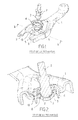
- la figure 1 représente, schématiquement et partiellement, en perspective, différentes pièces constitutives d'un système de débrayage connu de l'état de la technique, avant assemblage,
- la figure 2 est une vue schématique et partielle, en coupe selon II-II, du système de débrayage de la figure 1, après assemblage,
- les figures 3 et 4 représentent, schématiquement et partiellement, en perspective, respectivement de dessous et de dessus, un ensemble conforme à l'invention comportant un support et un patin,
- la figure 5 représente, schématiquement et partiellement, en perspective, un support conforme à un autre exemple de mise en oeuvre de l'invention,
- la figure 6 représente, schématiquement et partiellement, en perspective, le support de la figure 5, avec un patin fixé dessus,
- la figure 7 représente, schématiquement et partiellement, en perspective, un support conforme à un autre exemple de mise en oeuvre de l'invention, et
- la figure 8 représente, schématiquement et partiellement, en perspective, le support de la figure 7, avec un patin fixé dessus.
Claims (19)
- Ensemble (11) destiné à être mis en place sur la fourchette d'un système de débrayage de véhicule automobile, ledit ensemble comportant :caractérisé par le fait que le support (12) comporte des moyens de retenue (18 ; 23 ; 25 ; 27) pour permettre la fixation du patin (20) sur le support (12).un patin (20) formant une surface de glissement pour un embout (3) d'un axe de rotule (2) du système de débrayage,un support (12) comprenant un logement (17) pour recevoir l'embout (3) de l'axe de rotule (2),
- Ensemble selon la revendication 1, caractérisé par le fait que les moyens de retenue prévus sur le support (12) sont agencés de manière à ménager un jeu entre le patin et le support permettant un déplacement relatif du patin (20) par rapport au support (12).
- Ensemble selon l'une des revendications 1 et 2, caractérisé par le fait que les moyens de retenue comportent une ou plusieurs portées (18) sur laquelle ou lesquelles s'applique au moins une portion du patin, et un ou plusieurs reliefs de fixation (23 ; 25 ; 27) agencés pour maintenir le patin en appui sur la ou les portées (18).
- Ensemble selon la revendication 3, caractérisé par le fait que le ou les reliefs de fixation sont formés chacun par une patte élastiquement déformable (23).
- Ensemble selon la revendication 3, caractérisé par le fait que le ou les reliefs sont formés chacun par un picot (25) apte à être aplati, notamment par bouterollage.
- Ensemble selon la revendication 3, caractérisé par le fait que le relief de fixation est formé par une lèvre annulaire (27) apte à être déformée, notamment par bouterollage.
- Ensemble selon l'une quelconque des revendications 3 à 6, caractérisé par le fait que la portion du patin en appui sur la ou les portées est une portion périphérique (21) du patin (20).
- Ensemble selon l'une quelconque des revendications précédentes, caractérisé par le fait que le patin (20) comporte une portion périphérique annulaire sensiblement plane (21).
- Ensemble selon l'une quelconque des revendications 3 à 8, le support comportant une paroi intérieure cylindrique (14), caractérisé par le fait que la ou les portées (18) sont formées sur une ou plusieurs formes en saillie de la paroi intérieure (14).
- Ensemble selon l'une quelconque des revendications précédentes, caractérisé par le fait que le support (12) est réalisé d'un seul tenant en matière thermoplastique, notamment par moulage par injection.
- Ensemble selon l'une quelconque des revendications précédentes, caractérisé par le fait que le patin (20) est réalisé en un matériau choisi parmi : un matériau contenant du PTFE et une grille métallique, une matière thermoplastique, notamment un polyamide chargé, un polyimide, du POM, du PPS ou du PEEK.
- Système de débrayage de véhicule automobile, comportant :une fourchette de débrayage (1),un axe de rotule (2) comportant un embout (3),un ensemble (11) tel que défini dans l'une quelconque des revendications 1 à 11, fixé sur la fourchette de débrayage (1).
- Système de débrayage selon la revendication 12, caractérisé par le fait que la fourchette de débrayage (1) comporte un ou plusieurs orifices et par le fait que le support comporte une ou plusieurs pattes (16), notamment élastiquement déformables, aptes à s'engager dans le ou les orifices (19) de la fourchette, permettant la fixation du support sur la fourchette.
- Procédé de fabrication d'un ensemble (11) destiné à équiper un système de débrayage de véhicule automobile, caractérisé par le fait qu'il comporte les étapes suivantes :fournir un patin (20) formant une surface de glissement pour un embout (3) d'un axe de rotule (2) du système de débrayage,fournir un support (12) comportant un logement (17) pour recevoir l'embout (3) de l'axe de rotule (2) et agencé pour permettre la fixation du patin sur le support,fixer le patin sur le support.
- Procédé selon la revendication 14, caractérisé par le fait que le support (12) comporte un ou plusieurs reliefs de fixation (25 ; 27) aptes à être déformés, notamment par bouterollage, afin de permettre le maintien du patin sur le support.
- Procédé selon la revendication 15, caractérisé par le fait que la déformation du relief de fixation s'effectue à température ambiante.
- Procédé selon la revendication 15, caractérisé par le fait que, préalablement à la déformation du relief de fixation, le support est chauffé.
- Procédé selon la revendication 15, caractérisé par le fait que la déformation du relief de fixation s'effectue à l'aide d'un outil préchauffé.
- Procédé selon la revendication 15, caractérisé par le fait que la déformation du relief de fixation s'effectue à l'aide d'un outil sur lequel sont générés des ultrasons.
Applications Claiming Priority (2)
| Application Number | Priority Date | Filing Date | Title |
|---|---|---|---|
| FR0310696 | 2003-09-11 | ||
| FR0310696A FR2859772B1 (fr) | 2003-09-11 | 2003-09-11 | Ensemble pour systeme de debrayage de vehicule automobile |
Publications (2)
| Publication Number | Publication Date |
|---|---|
| EP1515058A1 true EP1515058A1 (fr) | 2005-03-16 |
| EP1515058B1 EP1515058B1 (fr) | 2006-07-26 |
Family
ID=34130793
Family Applications (1)
| Application Number | Title | Priority Date | Filing Date |
|---|---|---|---|
| EP04300576A Expired - Lifetime EP1515058B1 (fr) | 2003-09-11 | 2004-09-07 | Ensemble pour système de débrayage de véhicule automobile. |
Country Status (7)
| Country | Link |
|---|---|
| US (1) | US20050056517A1 (fr) |
| EP (1) | EP1515058B1 (fr) |
| AT (1) | ATE334320T1 (fr) |
| BR (1) | BRPI0403785A (fr) |
| DE (1) | DE602004001645T2 (fr) |
| FR (1) | FR2859772B1 (fr) |
| MX (1) | MXPA04008825A (fr) |
Families Citing this family (1)
| Publication number | Priority date | Publication date | Assignee | Title |
|---|---|---|---|---|
| JP2015001268A (ja) * | 2013-06-14 | 2015-01-05 | トヨタ自動車株式会社 | クラッチ装置 |
Citations (4)
| Publication number | Priority date | Publication date | Assignee | Title |
|---|---|---|---|---|
| US4773516A (en) * | 1986-04-12 | 1988-09-27 | Ina Walzlager Schaeffler Kg | Novel clutch lever support means |
| DE3801460C1 (en) * | 1988-01-20 | 1989-08-24 | Adam Opel Ag, 6090 Ruesselsheim, De | Motor-vehicle friction clutch that can be operated by means of a release lever |
| EP0379392A1 (fr) * | 1989-01-19 | 1990-07-25 | Automobiles Peugeot | Articulation à rotule |
| FR2722262A1 (fr) * | 1994-07-07 | 1996-01-12 | Renault Regie Nationale Usines | Dispositif de commande d'embrayage |
Family Cites Families (3)
| Publication number | Priority date | Publication date | Assignee | Title |
|---|---|---|---|---|
| JPH01172610A (ja) * | 1987-12-25 | 1989-07-07 | Ishikawa Tekko Kk | ポールジョイント及びその製造方法 |
| DE4433762C2 (de) * | 1994-09-22 | 1998-09-24 | Trw Fahrwerksyst Gmbh & Co | Kugelgelenk |
| US6123181A (en) * | 1998-07-28 | 2000-09-26 | Mannesmann Sachs Ag | Articulation head for a clutch-release rocker arm of a friction clutch |
-
2003
- 2003-09-11 FR FR0310696A patent/FR2859772B1/fr not_active Expired - Fee Related
-
2004
- 2004-09-07 EP EP04300576A patent/EP1515058B1/fr not_active Expired - Lifetime
- 2004-09-07 DE DE602004001645T patent/DE602004001645T2/de not_active Expired - Lifetime
- 2004-09-07 AT AT04300576T patent/ATE334320T1/de not_active IP Right Cessation
- 2004-09-09 US US10/937,743 patent/US20050056517A1/en not_active Abandoned
- 2004-09-09 BR BR0403785-5A patent/BRPI0403785A/pt not_active IP Right Cessation
- 2004-09-10 MX MXPA04008825A patent/MXPA04008825A/es unknown
Patent Citations (4)
| Publication number | Priority date | Publication date | Assignee | Title |
|---|---|---|---|---|
| US4773516A (en) * | 1986-04-12 | 1988-09-27 | Ina Walzlager Schaeffler Kg | Novel clutch lever support means |
| DE3801460C1 (en) * | 1988-01-20 | 1989-08-24 | Adam Opel Ag, 6090 Ruesselsheim, De | Motor-vehicle friction clutch that can be operated by means of a release lever |
| EP0379392A1 (fr) * | 1989-01-19 | 1990-07-25 | Automobiles Peugeot | Articulation à rotule |
| FR2722262A1 (fr) * | 1994-07-07 | 1996-01-12 | Renault Regie Nationale Usines | Dispositif de commande d'embrayage |
Also Published As
| Publication number | Publication date |
|---|---|
| FR2859772B1 (fr) | 2005-11-11 |
| DE602004001645D1 (de) | 2006-09-07 |
| US20050056517A1 (en) | 2005-03-17 |
| DE602004001645T2 (de) | 2007-08-09 |
| FR2859772A1 (fr) | 2005-03-18 |
| EP1515058B1 (fr) | 2006-07-26 |
| ATE334320T1 (de) | 2006-08-15 |
| MXPA04008825A (es) | 2005-04-19 |
| BRPI0403785A (pt) | 2005-05-24 |
Similar Documents
| Publication | Publication Date | Title |
|---|---|---|
| FR2544429A1 (fr) | Procede pour le montage d'une butee de debrayage, et butee de debrayage correspondante, notamment pour vehicule automobile | |
| FR2817596A1 (fr) | Systeme d'assemblage au moyen d'un dispositif d'ancrage a billes | |
| FR2565644A1 (fr) | Fixation d'un roulement dans un logement ou analogue | |
| FR2619880A1 (fr) | Butee de debrayage, notamment pour vehicules automobiles | |
| FR2538058A1 (fr) | Mecanisme d'embrayage, notamment pour vehicule automobile | |
| EP1080317B1 (fr) | Butee de debrayage a auto-alignement par manchon | |
| FR2626053A1 (fr) | Embrayage de verrouillage pour appareil d'accouplement hydrocinetique, notamment pour vehicule automobile | |
| FR2745616A1 (fr) | Dispositif de maintien, notamment pour vehicule automobile | |
| EP0845615B1 (fr) | Dispositif débrayeur | |
| EP0220982B1 (fr) | Montage de butée de débrayage, notamment pour véhicule automobile | |
| FR2777328A1 (fr) | Dispositif de manoeuvre pour un embrayage | |
| EP1918606B1 (fr) | Frein à disque | |
| EP1515058A1 (fr) | Ensemble pour système de débrayage de véhicule automobile. | |
| FR2791406A1 (fr) | Dispositif de montage d'un diaphragme sur un couvercle d'embrayage | |
| EP3234396B1 (fr) | Dispositif pour embrayage pour vehicule automobile | |
| EP4487025B1 (fr) | Mecanisme d'embrayage notamment pour vehicule motorise | |
| EP0111204B1 (fr) | Butée d'embrayage à amortissement de bruit et de vibrations | |
| FR2902476A1 (fr) | Ensemble de couvercle d'embrayage | |
| EP3346306A1 (fr) | Dispositif de raccordement amovible pour un guide de lumière et application dans un véhicule automobile, module à transmission optique pourvu du dispositif | |
| FR2722262A1 (fr) | Dispositif de commande d'embrayage | |
| FR2575251A1 (fr) | Embrayage a friction | |
| FR2671147A1 (fr) | Dispositif d'immobilisation de deux pieces assemblees par pression de l'une sur l'autre, en particulier pour vehicule automobile. | |
| FR2733808A1 (fr) | Embrayage a friction a rattrapage d'usure | |
| EP0213002A1 (fr) | Montage de butée de débrayage | |
| EP1914437A1 (fr) | Frein à disque de véhicule automobile comportant des moyens de rappel élastique d'une plaque de découplage dans une position centrale de repos. |
Legal Events
| Date | Code | Title | Description |
|---|---|---|---|
| PUAI | Public reference made under article 153(3) epc to a published international application that has entered the european phase |
Free format text: ORIGINAL CODE: 0009012 |
|
| AK | Designated contracting states |
Kind code of ref document: A1 Designated state(s): AT BE BG CH CY CZ DE DK EE ES FI FR GB GR HU IE IT LI LU MC NL PL PT RO SE SI SK TR |
|
| AX | Request for extension of the european patent |
Extension state: AL HR LT LV MK |
|
| 17P | Request for examination filed |
Effective date: 20050604 |
|
| AKX | Designation fees paid |
Designated state(s): AT BE BG CH CY CZ DE DK EE ES FI FR GB GR HU IE IT LI LU MC NL PL PT RO SE SI SK TR |
|
| GRAP | Despatch of communication of intention to grant a patent |
Free format text: ORIGINAL CODE: EPIDOSNIGR1 |
|
| GRAS | Grant fee paid |
Free format text: ORIGINAL CODE: EPIDOSNIGR3 |
|
| GRAA | (expected) grant |
Free format text: ORIGINAL CODE: 0009210 |
|
| AK | Designated contracting states |
Kind code of ref document: B1 Designated state(s): AT BE BG CH CY CZ DE DK EE ES FI FR GB GR HU IE IT LI LU MC NL PL PT RO SE SI SK TR |
|
| PG25 | Lapsed in a contracting state [announced via postgrant information from national office to epo] |
Ref country code: FI Free format text: LAPSE BECAUSE OF FAILURE TO SUBMIT A TRANSLATION OF THE DESCRIPTION OR TO PAY THE FEE WITHIN THE PRESCRIBED TIME-LIMIT Effective date: 20060726 Ref country code: IT Free format text: LAPSE BECAUSE OF FAILURE TO SUBMIT A TRANSLATION OF THE DESCRIPTION OR TO PAY THE FEE WITHIN THE PRESCRIBED TIME-LIMIT;WARNING: LAPSES OF ITALIAN PATENTS WITH EFFECTIVE DATE BEFORE 2007 MAY HAVE OCCURRED AT ANY TIME BEFORE 2007. THE CORRECT EFFECTIVE DATE MAY BE DIFFERENT FROM THE ONE RECORDED. Effective date: 20060726 Ref country code: CZ Free format text: LAPSE BECAUSE OF FAILURE TO SUBMIT A TRANSLATION OF THE DESCRIPTION OR TO PAY THE FEE WITHIN THE PRESCRIBED TIME-LIMIT Effective date: 20060726 Ref country code: GB Free format text: LAPSE BECAUSE OF FAILURE TO SUBMIT A TRANSLATION OF THE DESCRIPTION OR TO PAY THE FEE WITHIN THE PRESCRIBED TIME-LIMIT Effective date: 20060726 Ref country code: SI Free format text: LAPSE BECAUSE OF FAILURE TO SUBMIT A TRANSLATION OF THE DESCRIPTION OR TO PAY THE FEE WITHIN THE PRESCRIBED TIME-LIMIT Effective date: 20060726 Ref country code: AT Free format text: LAPSE BECAUSE OF FAILURE TO SUBMIT A TRANSLATION OF THE DESCRIPTION OR TO PAY THE FEE WITHIN THE PRESCRIBED TIME-LIMIT Effective date: 20060726 Ref country code: SK Free format text: LAPSE BECAUSE OF FAILURE TO SUBMIT A TRANSLATION OF THE DESCRIPTION OR TO PAY THE FEE WITHIN THE PRESCRIBED TIME-LIMIT Effective date: 20060726 Ref country code: RO Free format text: LAPSE BECAUSE OF FAILURE TO SUBMIT A TRANSLATION OF THE DESCRIPTION OR TO PAY THE FEE WITHIN THE PRESCRIBED TIME-LIMIT Effective date: 20060726 Ref country code: IE Free format text: LAPSE BECAUSE OF FAILURE TO SUBMIT A TRANSLATION OF THE DESCRIPTION OR TO PAY THE FEE WITHIN THE PRESCRIBED TIME-LIMIT Effective date: 20060726 Ref country code: PL Free format text: LAPSE BECAUSE OF FAILURE TO SUBMIT A TRANSLATION OF THE DESCRIPTION OR TO PAY THE FEE WITHIN THE PRESCRIBED TIME-LIMIT Effective date: 20060726 Ref country code: NL Free format text: LAPSE BECAUSE OF FAILURE TO SUBMIT A TRANSLATION OF THE DESCRIPTION OR TO PAY THE FEE WITHIN THE PRESCRIBED TIME-LIMIT Effective date: 20060726 |
|
| REG | Reference to a national code |
Ref country code: GB Ref legal event code: FG4D Free format text: NOT ENGLISH |
|
| REG | Reference to a national code |
Ref country code: CH Ref legal event code: EP |
|
| REG | Reference to a national code |
Ref country code: IE Ref legal event code: FG4D Free format text: LANGUAGE OF EP DOCUMENT: FRENCH |
|
| REF | Corresponds to: |
Ref document number: 602004001645 Country of ref document: DE Date of ref document: 20060907 Kind code of ref document: P |
|
| PG25 | Lapsed in a contracting state [announced via postgrant information from national office to epo] |
Ref country code: MC Free format text: LAPSE BECAUSE OF NON-PAYMENT OF DUE FEES Effective date: 20060930 Ref country code: BE Free format text: LAPSE BECAUSE OF NON-PAYMENT OF DUE FEES Effective date: 20060930 |
|
| PG25 | Lapsed in a contracting state [announced via postgrant information from national office to epo] |
Ref country code: DK Free format text: LAPSE BECAUSE OF FAILURE TO SUBMIT A TRANSLATION OF THE DESCRIPTION OR TO PAY THE FEE WITHIN THE PRESCRIBED TIME-LIMIT Effective date: 20061026 Ref country code: SE Free format text: LAPSE BECAUSE OF FAILURE TO SUBMIT A TRANSLATION OF THE DESCRIPTION OR TO PAY THE FEE WITHIN THE PRESCRIBED TIME-LIMIT Effective date: 20061026 Ref country code: BG Free format text: LAPSE BECAUSE OF FAILURE TO SUBMIT A TRANSLATION OF THE DESCRIPTION OR TO PAY THE FEE WITHIN THE PRESCRIBED TIME-LIMIT Effective date: 20061026 |
|
| PG25 | Lapsed in a contracting state [announced via postgrant information from national office to epo] |
Ref country code: ES Free format text: LAPSE BECAUSE OF FAILURE TO SUBMIT A TRANSLATION OF THE DESCRIPTION OR TO PAY THE FEE WITHIN THE PRESCRIBED TIME-LIMIT Effective date: 20061106 |
|
| PG25 | Lapsed in a contracting state [announced via postgrant information from national office to epo] |
Ref country code: PT Free format text: LAPSE BECAUSE OF FAILURE TO SUBMIT A TRANSLATION OF THE DESCRIPTION OR TO PAY THE FEE WITHIN THE PRESCRIBED TIME-LIMIT Effective date: 20061226 |
|
| NLV1 | Nl: lapsed or annulled due to failure to fulfill the requirements of art. 29p and 29m of the patents act | ||
| GBV | Gb: ep patent (uk) treated as always having been void in accordance with gb section 77(7)/1977 [no translation filed] |
Effective date: 20060726 |
|
| REG | Reference to a national code |
Ref country code: IE Ref legal event code: FD4D |
|
| PLBE | No opposition filed within time limit |
Free format text: ORIGINAL CODE: 0009261 |
|
| STAA | Information on the status of an ep patent application or granted ep patent |
Free format text: STATUS: NO OPPOSITION FILED WITHIN TIME LIMIT |
|
| 26N | No opposition filed |
Effective date: 20070427 |
|
| BERE | Be: lapsed |
Owner name: CIE PLASTIC OMNIUM Effective date: 20060930 |
|
| PG25 | Lapsed in a contracting state [announced via postgrant information from national office to epo] |
Ref country code: GR Free format text: LAPSE BECAUSE OF FAILURE TO SUBMIT A TRANSLATION OF THE DESCRIPTION OR TO PAY THE FEE WITHIN THE PRESCRIBED TIME-LIMIT Effective date: 20061027 |
|
| PG25 | Lapsed in a contracting state [announced via postgrant information from national office to epo] |
Ref country code: EE Free format text: LAPSE BECAUSE OF FAILURE TO SUBMIT A TRANSLATION OF THE DESCRIPTION OR TO PAY THE FEE WITHIN THE PRESCRIBED TIME-LIMIT Effective date: 20060726 |
|
| PG25 | Lapsed in a contracting state [announced via postgrant information from national office to epo] |
Ref country code: TR Free format text: LAPSE BECAUSE OF FAILURE TO SUBMIT A TRANSLATION OF THE DESCRIPTION OR TO PAY THE FEE WITHIN THE PRESCRIBED TIME-LIMIT Effective date: 20060726 Ref country code: HU Free format text: LAPSE BECAUSE OF FAILURE TO SUBMIT A TRANSLATION OF THE DESCRIPTION OR TO PAY THE FEE WITHIN THE PRESCRIBED TIME-LIMIT Effective date: 20070127 Ref country code: LU Free format text: LAPSE BECAUSE OF NON-PAYMENT OF DUE FEES Effective date: 20060907 |
|
| PG25 | Lapsed in a contracting state [announced via postgrant information from national office to epo] |
Ref country code: CY Free format text: LAPSE BECAUSE OF FAILURE TO SUBMIT A TRANSLATION OF THE DESCRIPTION OR TO PAY THE FEE WITHIN THE PRESCRIBED TIME-LIMIT Effective date: 20060726 |
|
| REG | Reference to a national code |
Ref country code: CH Ref legal event code: PL |
|
| PG25 | Lapsed in a contracting state [announced via postgrant information from national office to epo] |
Ref country code: LI Free format text: LAPSE BECAUSE OF NON-PAYMENT OF DUE FEES Effective date: 20060930 Ref country code: CH Free format text: LAPSE BECAUSE OF NON-PAYMENT OF DUE FEES Effective date: 20060930 |
|
| PG25 | Lapsed in a contracting state [announced via postgrant information from national office to epo] |
Ref country code: CH Free format text: LAPSE BECAUSE OF NON-PAYMENT OF DUE FEES Effective date: 20080930 Ref country code: LI Free format text: LAPSE BECAUSE OF NON-PAYMENT OF DUE FEES Effective date: 20080930 |
|
| REG | Reference to a national code |
Ref country code: FR Ref legal event code: PLFP Year of fee payment: 13 |
|
| REG | Reference to a national code |
Ref country code: FR Ref legal event code: PLFP Year of fee payment: 14 |
|
| REG | Reference to a national code |
Ref country code: FR Ref legal event code: PLFP Year of fee payment: 15 |
|
| PGFP | Annual fee paid to national office [announced via postgrant information from national office to epo] |
Ref country code: FR Payment date: 20230929 Year of fee payment: 20 Ref country code: DE Payment date: 20230920 Year of fee payment: 20 |
|
| REG | Reference to a national code |
Ref country code: DE Ref legal event code: R071 Ref document number: 602004001645 Country of ref document: DE |