EP1515105A2 - Wärmetauscher und Herstellungsverfahren - Google Patents
Wärmetauscher und Herstellungsverfahren Download PDFInfo
- Publication number
- EP1515105A2 EP1515105A2 EP04460028A EP04460028A EP1515105A2 EP 1515105 A2 EP1515105 A2 EP 1515105A2 EP 04460028 A EP04460028 A EP 04460028A EP 04460028 A EP04460028 A EP 04460028A EP 1515105 A2 EP1515105 A2 EP 1515105A2
- Authority
- EP
- European Patent Office
- Prior art keywords
- heat exchanger
- header tanks
- end caps
- projections
- openings
- Prior art date
- Legal status (The legal status is an assumption and is not a legal conclusion. Google has not performed a legal analysis and makes no representation as to the accuracy of the status listed.)
- Granted
Links
Images


Classifications
-
- F—MECHANICAL ENGINEERING; LIGHTING; HEATING; WEAPONS; BLASTING
- F28—HEAT EXCHANGE IN GENERAL
- F28D—HEAT-EXCHANGE APPARATUS, NOT PROVIDED FOR IN ANOTHER SUBCLASS, IN WHICH THE HEAT-EXCHANGE MEDIA DO NOT COME INTO DIRECT CONTACT
- F28D1/00—Heat-exchange apparatus having stationary conduit assemblies for one heat-exchange medium only, the media being in contact with different sides of the conduit wall, in which the other heat-exchange medium is a large body of fluid, e.g. domestic or motor car radiators
- F28D1/02—Heat-exchange apparatus having stationary conduit assemblies for one heat-exchange medium only, the media being in contact with different sides of the conduit wall, in which the other heat-exchange medium is a large body of fluid, e.g. domestic or motor car radiators with heat-exchange conduits immersed in the body of fluid
- F28D1/04—Heat-exchange apparatus having stationary conduit assemblies for one heat-exchange medium only, the media being in contact with different sides of the conduit wall, in which the other heat-exchange medium is a large body of fluid, e.g. domestic or motor car radiators with heat-exchange conduits immersed in the body of fluid with tubular conduits
- F28D1/0408—Multi-circuit heat exchangers, e.g. integrating different heat exchange sections in the same unit or heat exchangers for more than two fluids
- F28D1/0426—Multi-circuit heat exchangers, e.g. integrating different heat exchange sections in the same unit or heat exchangers for more than two fluids with units having particular arrangement relative to the large body of fluid, e.g. with interleaved units or with adjacent heat exchange units in common air flow or with units extending at an angle to each other or with units arranged around a central element
- F28D1/0435—Combination of units extending one behind the other
-
- F—MECHANICAL ENGINEERING; LIGHTING; HEATING; WEAPONS; BLASTING
- F28—HEAT EXCHANGE IN GENERAL
- F28F—DETAILS OF HEAT-EXCHANGE AND HEAT-TRANSFER APPARATUS, OF GENERAL APPLICATION
- F28F9/00—Casings; Header boxes; Auxiliary supports for elements; Auxiliary members within casings
- F28F9/001—Casings in the form of plate-like arrangements; Frames enclosing a heat exchange core
- F28F9/002—Casings in the form of plate-like arrangements; Frames enclosing a heat exchange core with fastening means for other structures
-
- F—MECHANICAL ENGINEERING; LIGHTING; HEATING; WEAPONS; BLASTING
- F28—HEAT EXCHANGE IN GENERAL
- F28F—DETAILS OF HEAT-EXCHANGE AND HEAT-TRANSFER APPARATUS, OF GENERAL APPLICATION
- F28F9/00—Casings; Header boxes; Auxiliary supports for elements; Auxiliary members within casings
- F28F9/02—Header boxes; End plates
- F28F9/0202—Header boxes having their inner space divided by partitions
-
- F—MECHANICAL ENGINEERING; LIGHTING; HEATING; WEAPONS; BLASTING
- F28—HEAT EXCHANGE IN GENERAL
- F28D—HEAT-EXCHANGE APPARATUS, NOT PROVIDED FOR IN ANOTHER SUBCLASS, IN WHICH THE HEAT-EXCHANGE MEDIA DO NOT COME INTO DIRECT CONTACT
- F28D1/00—Heat-exchange apparatus having stationary conduit assemblies for one heat-exchange medium only, the media being in contact with different sides of the conduit wall, in which the other heat-exchange medium is a large body of fluid, e.g. domestic or motor car radiators
- F28D1/02—Heat-exchange apparatus having stationary conduit assemblies for one heat-exchange medium only, the media being in contact with different sides of the conduit wall, in which the other heat-exchange medium is a large body of fluid, e.g. domestic or motor car radiators with heat-exchange conduits immersed in the body of fluid
- F28D1/04—Heat-exchange apparatus having stationary conduit assemblies for one heat-exchange medium only, the media being in contact with different sides of the conduit wall, in which the other heat-exchange medium is a large body of fluid, e.g. domestic or motor car radiators with heat-exchange conduits immersed in the body of fluid with tubular conduits
- F28D1/053—Heat-exchange apparatus having stationary conduit assemblies for one heat-exchange medium only, the media being in contact with different sides of the conduit wall, in which the other heat-exchange medium is a large body of fluid, e.g. domestic or motor car radiators with heat-exchange conduits immersed in the body of fluid with tubular conduits the conduits being straight
- F28D1/0535—Heat-exchange apparatus having stationary conduit assemblies for one heat-exchange medium only, the media being in contact with different sides of the conduit wall, in which the other heat-exchange medium is a large body of fluid, e.g. domestic or motor car radiators with heat-exchange conduits immersed in the body of fluid with tubular conduits the conduits being straight the conduits having a non-circular cross-section
- F28D1/05366—Assemblies of conduits connected to common headers, e.g. core type radiators
-
- F—MECHANICAL ENGINEERING; LIGHTING; HEATING; WEAPONS; BLASTING
- F28—HEAT EXCHANGE IN GENERAL
- F28F—DETAILS OF HEAT-EXCHANGE AND HEAT-TRANSFER APPARATUS, OF GENERAL APPLICATION
- F28F2220/00—Closure means, e.g. end caps on header boxes or plugs on conduits
-
- F—MECHANICAL ENGINEERING; LIGHTING; HEATING; WEAPONS; BLASTING
- F28—HEAT EXCHANGE IN GENERAL
- F28F—DETAILS OF HEAT-EXCHANGE AND HEAT-TRANSFER APPARATUS, OF GENERAL APPLICATION
- F28F2275/00—Fastening; Joining
- F28F2275/14—Fastening; Joining by using form fitting connection, e.g. with tongue and groove
Definitions
- the present invention relates to an integrated heat exchanger comprising at least two heat exchangers, each having a cooling core comprised of fins and tubes, two header tanks fluidly connected with reciprocal ends of cooling core tubes, where said heat exchangers are coupled and parallel to each other.
- the invention further relates to a method of assembling such a heat exchanger.
- Integrated heat exchangers of this kind commonly form a vehicle CRFM (Condenser, Radiator, cooling Fan Module), where a condenser of the vehicle air conditioning system is connected in stacking direction to the engine cooling installation radiator.
- vehicle CRFM Condenser, Radiator, cooling Fan Module
- Examples of such modules are disclosed in U.S. Pat. No.: 6,364,005, GB Pat. 2 371 505 or U.S. Pat. ADD. No. 10/350,360.
- radiator is coupled to condenser with end caps closing the header tank openings, by means of appropriate brackets or, as in GB Pat. 2 371 505, with a clinched seam, and then the whole unit is brazed in a furnace.
- the above methods form CRFMs which are inseparable units, disallowing to detach previously coupled heat exchangers. If any of heat exchangers fails, e.g. gets leak, the whole CRFM needs to be dismounted and then repaired or replaced.
- an integrated heat exchanger where the top ends of the header tanks of the primary heat exchanger are provided with top end caps having projections with openings adapted to receive the top ends of the header tanks of at least one secondary heat exchanger; the bottom ends of the header tanks of the primary heat exchanger are provided with bottom end caps having projections with sockets adapted to receive the bottom ends of the header tanks of at least one secondary heat exchanger; where the bottom ends of the header tanks of at least one secondary heat exchanger are supported on a retaining rings resting in sockets of the projections of the bottom end caps; and the top ends of the header tanks of at least one secondary heat exchanger, are locked by retaining plugs pushed upwardly into the openings of the projections of the top end caps.
- the primary heat exchanger is a radiator of a vehicle cooling system and the secondary heat exchanger is a condenser of a vehicle air conditioning system.
- the retaining rings and the retaining plugs are made of resilient material, advantageously plastic.
- Such mounting system eliminates possible displacements of particular elements, compensates dimensional manufacturing tolerances of the condenser and the radiator, and provides an amortization effect during the engine operation.
- the system enables also thermal stresses compensation caused by coolant temperature differences in particular heat exchangers.
- bottom and top end caps may be mounted to the primary heat exchanger after brazing thereof.
- the procedure described above may be also performed for each third and any subsequent heat exchanger of the integrated heat exchanger.
- the method according to the present invention allows a reliable coupling a number of heat exchangers in uncomplicated way, at the same time avoiding additional operations of preassembling or positioning.
- Application of only two pairs of end caps, provided with retaining plugs and retaining rings, permits to keep the right position of heat exchangers with respect to each other, wherein at the same time it is possible to detach such a connection, which is advantageous in servicing the integrated module, e.g. by replacing condenser that has failed.
- the portion of the integrated heat exchanger 1 according to one embodiment of the present invention is presented in Fig. 1, where the heat exchanger 1 forms an integrated vehicle CRFM module.
- the heat exchanger 1 comprises in fact of two heat exchangers: the radiator 2 of the vehicle cooling system and the condenser 3 of the vehicle air conditioning systems.
- the drawing presents only top and bottom ends of the heat exchangers 2 and 3.
- Radiator 2 comprises of two header tanks 21 (only one shown on the drawing) having a rectangular cross-section and fluidly connected with reciprocal ends of tubes 22, that along with cooling fins 23 located in regions between the tubes 22 form the radiator cooling core. Ends of tubes 22 are inserted in grooves 24.
- the construction of the condenser 3 is similar. It comprises of two circular header tanks 31 fluidly connected with tubes 32 inserted into appropriate grooves 34. The tubes 32 and the cooling fins 33 located in regions between the tubes 32 form the condenser cooling core shown in part in the drawing.
- Heat exchangers 2 and 3 are manufactured independently i.e. they are independently preassembled and brazed in a furnace.
- the open ends of the condenser 3 header tanks 31 are closed by the end caps 35 recessed inside the header tank 31 profile.
- top end cap 4 The open top end of the radiator 2 header tank 21 is closed by top end cap 4 and the bottom end by bottom end cap 5.
- the end caps 4 and 5 have been manufactured by a cup-ironing method and then brazed to the header tanks 21 in the course of brazing of the radiator 2. In the presented embodiment they additionally serve as separators closing the profiles of the header tanks 21.
- Top end caps 4 have projections 41 with openings 43, having a diameter greater than the diameter of the condenser 3 header tanks 31.
- bottom end caps 5 have the similar projections 51 with sockets (not shown in the drawing).
- the construction additionally comprise retaining plugs 42 shown in detached position and provided with a circumferential snap 45, and retaining rings 52 resting in sockets of the projections 51 of the bottom end caps 5.
- the plugs and the rings are made of plastic as single-unit elements.
- Fig. 2 presents the process of assembling the integrated heat exchanger 1.
- the first step is to place the retaining rings 52 in the sockets of the bottom end caps.
- the retaining rings 52 have an inner diameter tight-fitted to the outer diameter of the circular header tanks 31 of the condenser 3.
- Next step is to insert the top ends of the condenser header tanks 31 at an acute angle into openings 43 in projections 41 of the top end caps 4. Then one should turn the condenser 3 to obtain its parallel position with respect to the radiator 2 cooling core and displace it down, so as to place ends of its header tanks 31 into retaining rings 52.
- Fig. 3 The last step of assembly process is presented in Fig. 3, showing the heat exchanger after its assembling, in partial cross-section with details of the retaining plug 42.
- the top ends of the header tanks 31 of the condenser 3 are locked with the retaining plugs 42 pushed upwardly into the openings 43 of the projections 41 of the top end cap 4, until the circumferential snaps 45 lock behind the edges of the openings 43.
- the diameter of the opening 43 in projection 41 of the top end cap 4 is greater than the diameter of the second header tank 31 so as to enable the insertion of the header tanks 31 into the top end cap at a certain acute angle to the radiator cooling core.
- the plug 42 tightly fills the space between the wall of the opening and the wall of the header tank.
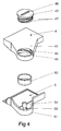
- Fig. 4 shows another embodiment of the essential elements forming the integrated exchanger according to the present invention. Reference numerals denoting the same functional elements remain unchanged.
- the socket 53 in the projection 51 of the bottom end cap 5 is defined by rounded vertical wall along the periphery of projection 51, and by a vertical protrusion 54 cut out in the projection 51 horizontal surface and then bent upwardly at straight angle.
- the diameter of the socket 53 is tightly fitted to the external diameter of the retaining ring 52, having internal wall adapted to receive the bottom end of the condenser.
- the opening 43 in the projection 41 of the top end cap 4 is provided with internal thread 46 corresponding to the external thread 47 on the wall of the retaining plug 42.
- a screwdriver placed in the appropriate recess 48 provided in the retaining plug 42.
- the integrated heat exchanger does not need to form a vehicle radiator condenser CRFM module; that the method enables assembling more than two heat exchangers in parallel; that the header tanks profiles may have any appropriate cross-sections i.e. oval, rectangular, double plated with seam, folded, etc.; that the end caps may be attached to the primary heat exchanger after its finishing; and the retaining plug may be provided with other types of locking arrangements.
- Other modifications of the invention are also possible, without departing from the spirit of invention and its scope of protection as indicated in appended claims.
Landscapes
- Engineering & Computer Science (AREA)
- Physics & Mathematics (AREA)
- Thermal Sciences (AREA)
- Mechanical Engineering (AREA)
- General Engineering & Computer Science (AREA)
- Details Of Heat-Exchange And Heat-Transfer (AREA)
- Air-Conditioning For Vehicles (AREA)
- Heat-Exchange Devices With Radiators And Conduit Assemblies (AREA)
- Separation By Low-Temperature Treatments (AREA)
- Making Paper Articles (AREA)
- Arrangement Or Mounting Of Propulsion Units For Vehicles (AREA)
- Motor Or Generator Cooling System (AREA)
Applications Claiming Priority (2)
| Application Number | Priority Date | Filing Date | Title |
|---|---|---|---|
| GBGB0321092.9A GB0321092D0 (en) | 2003-09-10 | 2003-09-10 | Radiator for a motor vehicle |
| GB0321092 | 2003-09-10 |
Publications (3)
| Publication Number | Publication Date |
|---|---|
| EP1515105A2 true EP1515105A2 (de) | 2005-03-16 |
| EP1515105A3 EP1515105A3 (de) | 2009-05-06 |
| EP1515105B1 EP1515105B1 (de) | 2010-10-20 |
Family
ID=29226753
Family Applications (1)
| Application Number | Title | Priority Date | Filing Date |
|---|---|---|---|
| EP04460028A Expired - Lifetime EP1515105B1 (de) | 2003-09-10 | 2004-06-28 | Wärmetauscher und Herstellungsverfahren |
Country Status (4)
| Country | Link |
|---|---|
| EP (1) | EP1515105B1 (de) |
| AT (2) | ATE479067T1 (de) |
| DE (2) | DE602004028784D1 (de) |
| GB (1) | GB0321092D0 (de) |
Cited By (4)
| Publication number | Priority date | Publication date | Assignee | Title |
|---|---|---|---|---|
| EP1757889A1 (de) * | 2005-08-24 | 2007-02-28 | Behr France Hambach S.A.R.L. | Sammelbehälter, insbesondere für einen Kondensator einer Klimaanlage, mit einem Verschluss |
| DE102009031696A1 (de) * | 2009-07-04 | 2011-01-05 | Modine Manufacturing Co., Racine | Wärmetauscheranordnung |
| EP2647943A3 (de) * | 2012-04-04 | 2014-08-13 | Industrias Royal Termic, S.L. | Endverschlusselement eines Heizkörpers |
| CN105333761A (zh) * | 2014-08-13 | 2016-02-17 | 杨朝阳 | 换热器管箱的集成结构 |
Family Cites Families (2)
| Publication number | Priority date | Publication date | Assignee | Title |
|---|---|---|---|---|
| AU729629B2 (en) * | 1996-08-12 | 2001-02-08 | Calsonic Corporation | Integral-type heat exchanger |
| JP4106194B2 (ja) * | 2001-02-28 | 2008-06-25 | カルソニックカンセイ株式会社 | 一体型熱交換器のタンク構造 |
-
2003
- 2003-09-10 GB GBGB0321092.9A patent/GB0321092D0/en not_active Ceased
-
2004
- 2004-05-31 AT AT04460017T patent/ATE479067T1/de not_active IP Right Cessation
- 2004-05-31 DE DE602004028784T patent/DE602004028784D1/de not_active Expired - Lifetime
- 2004-06-28 EP EP04460028A patent/EP1515105B1/de not_active Expired - Lifetime
- 2004-06-28 DE DE602004029637T patent/DE602004029637D1/de not_active Expired - Lifetime
- 2004-06-28 AT AT04460028T patent/ATE485486T1/de not_active IP Right Cessation
Cited By (5)
| Publication number | Priority date | Publication date | Assignee | Title |
|---|---|---|---|---|
| EP1757889A1 (de) * | 2005-08-24 | 2007-02-28 | Behr France Hambach S.A.R.L. | Sammelbehälter, insbesondere für einen Kondensator einer Klimaanlage, mit einem Verschluss |
| DE102009031696A1 (de) * | 2009-07-04 | 2011-01-05 | Modine Manufacturing Co., Racine | Wärmetauscheranordnung |
| EP2647943A3 (de) * | 2012-04-04 | 2014-08-13 | Industrias Royal Termic, S.L. | Endverschlusselement eines Heizkörpers |
| CN105333761A (zh) * | 2014-08-13 | 2016-02-17 | 杨朝阳 | 换热器管箱的集成结构 |
| CN105333761B (zh) * | 2014-08-13 | 2018-06-05 | 杨朝阳 | 换热器管箱的集成结构 |
Also Published As
| Publication number | Publication date |
|---|---|
| GB0321092D0 (en) | 2003-10-08 |
| EP1515105A3 (de) | 2009-05-06 |
| DE602004029637D1 (de) | 2010-12-02 |
| EP1515105B1 (de) | 2010-10-20 |
| ATE485486T1 (de) | 2010-11-15 |
| DE602004028784D1 (de) | 2010-10-07 |
| ATE479067T1 (de) | 2010-09-15 |
Similar Documents
| Publication | Publication Date | Title |
|---|---|---|
| EP0450619B1 (de) | Schirm für eine Endkammer eines Wärmetauschers | |
| US6460610B2 (en) | Welded heat exchanger with grommet construction | |
| AU728837B2 (en) | Heat exchanger assembly utilizing grommets and integral cast tanks | |
| EP1739380B1 (de) | Ölkühler | |
| US7040380B1 (en) | Bracket for motor vehicle air conditioner heat exchanger | |
| US11747096B2 (en) | Heat exchanging module having a housing comprising an inner frame and an outer frame | |
| EP0974793A2 (de) | Mit Sammler ausgerüsteter Verflüssiger | |
| US6607025B2 (en) | Heat-exchange module for a motor vehicle | |
| JP4109746B2 (ja) | 一体型熱交換器 | |
| CN100458352C (zh) | 换热器的箱结构 | |
| EP1515105B1 (de) | Wärmetauscher und Herstellungsverfahren | |
| KR20010068204A (ko) | 자동차 열교환기용 헤드어셈블리 | |
| JP4782520B2 (ja) | コンデンサのコネクタ固定構造 | |
| US20020084064A1 (en) | Integrated heat exchanger support and sealing structure | |
| KR20180023184A (ko) | 일체형 라디에이터 및 이의 조립 방법 | |
| US20150345877A1 (en) | Combined heat exchanger | |
| JP2007163055A (ja) | レシーバタンク付き熱交換器 | |
| JP2002004861A (ja) | 送風機の取付構造 | |
| US7900693B2 (en) | Soldered heat exchanger, in particular a condenser for motor vehicles | |
| EP1517108B1 (de) | Wärmetauscher | |
| US20070181293A1 (en) | Heat exchanger and producing method thereof | |
| JPH09217967A (ja) | コンデンサのヘッダとリキッドタンクとの結合装置 | |
| KR20170004524A (ko) | 쿨링 모듈 | |
| JPH04131667A (ja) | 凝縮器 | |
| KR101855890B1 (ko) | 쿨링모듈 |
Legal Events
| Date | Code | Title | Description |
|---|---|---|---|
| PUAI | Public reference made under article 153(3) epc to a published international application that has entered the european phase |
Free format text: ORIGINAL CODE: 0009012 |
|
| AK | Designated contracting states |
Kind code of ref document: A2 Designated state(s): AT BE BG CH CY CZ DE DK EE ES FI FR GB GR HU IE IT LI LU MC NL PL PT RO SE SI SK TR |
|
| AX | Request for extension of the european patent |
Extension state: AL HR LT LV MK |
|
| PUAL | Search report despatched |
Free format text: ORIGINAL CODE: 0009013 |
|
| AK | Designated contracting states |
Kind code of ref document: A3 Designated state(s): AT BE BG CH CY CZ DE DK EE ES FI FR GB GR HU IE IT LI LU MC NL PL PT RO SE SI SK TR |
|
| AX | Request for extension of the european patent |
Extension state: AL HR LT LV MK |
|
| 17P | Request for examination filed |
Effective date: 20091106 |
|
| AKX | Designation fees paid |
Designated state(s): AT BE BG CH CY CZ DE DK EE ES FI FR GB GR HU IE IT LI LU MC NL PL PT RO SE SI SK TR |
|
| GRAP | Despatch of communication of intention to grant a patent |
Free format text: ORIGINAL CODE: EPIDOSNIGR1 |
|
| GRAC | Information related to communication of intention to grant a patent modified |
Free format text: ORIGINAL CODE: EPIDOSCIGR1 |
|
| GRAS | Grant fee paid |
Free format text: ORIGINAL CODE: EPIDOSNIGR3 |
|
| GRAA | (expected) grant |
Free format text: ORIGINAL CODE: 0009210 |
|
| AK | Designated contracting states |
Kind code of ref document: B1 Designated state(s): AT BE BG CH CY CZ DE DK EE ES FI FR GB GR HU IE IT LI LU MC NL PL PT RO SE SI SK TR |
|
| REG | Reference to a national code |
Ref country code: GB Ref legal event code: FG4D |
|
| REG | Reference to a national code |
Ref country code: CH Ref legal event code: EP |
|
| REG | Reference to a national code |
Ref country code: IE Ref legal event code: FG4D |
|
| REF | Corresponds to: |
Ref document number: 602004029637 Country of ref document: DE Date of ref document: 20101202 Kind code of ref document: P |
|
| REG | Reference to a national code |
Ref country code: NL Ref legal event code: VDEP Effective date: 20101020 |
|
| PG25 | Lapsed in a contracting state [announced via postgrant information from national office to epo] |
Ref country code: SE Free format text: LAPSE BECAUSE OF FAILURE TO SUBMIT A TRANSLATION OF THE DESCRIPTION OR TO PAY THE FEE WITHIN THE PRESCRIBED TIME-LIMIT Effective date: 20101020 Ref country code: SI Free format text: LAPSE BECAUSE OF FAILURE TO SUBMIT A TRANSLATION OF THE DESCRIPTION OR TO PAY THE FEE WITHIN THE PRESCRIBED TIME-LIMIT Effective date: 20101020 Ref country code: BG Free format text: LAPSE BECAUSE OF FAILURE TO SUBMIT A TRANSLATION OF THE DESCRIPTION OR TO PAY THE FEE WITHIN THE PRESCRIBED TIME-LIMIT Effective date: 20110120 Ref country code: AT Free format text: LAPSE BECAUSE OF FAILURE TO SUBMIT A TRANSLATION OF THE DESCRIPTION OR TO PAY THE FEE WITHIN THE PRESCRIBED TIME-LIMIT Effective date: 20101020 Ref country code: PT Free format text: LAPSE BECAUSE OF FAILURE TO SUBMIT A TRANSLATION OF THE DESCRIPTION OR TO PAY THE FEE WITHIN THE PRESCRIBED TIME-LIMIT Effective date: 20110221 Ref country code: FI Free format text: LAPSE BECAUSE OF FAILURE TO SUBMIT A TRANSLATION OF THE DESCRIPTION OR TO PAY THE FEE WITHIN THE PRESCRIBED TIME-LIMIT Effective date: 20101020 Ref country code: NL Free format text: LAPSE BECAUSE OF FAILURE TO SUBMIT A TRANSLATION OF THE DESCRIPTION OR TO PAY THE FEE WITHIN THE PRESCRIBED TIME-LIMIT Effective date: 20101020 |
|
| PG25 | Lapsed in a contracting state [announced via postgrant information from national office to epo] |
Ref country code: GR Free format text: LAPSE BECAUSE OF FAILURE TO SUBMIT A TRANSLATION OF THE DESCRIPTION OR TO PAY THE FEE WITHIN THE PRESCRIBED TIME-LIMIT Effective date: 20110121 Ref country code: BE Free format text: LAPSE BECAUSE OF FAILURE TO SUBMIT A TRANSLATION OF THE DESCRIPTION OR TO PAY THE FEE WITHIN THE PRESCRIBED TIME-LIMIT Effective date: 20101020 |
|
| PG25 | Lapsed in a contracting state [announced via postgrant information from national office to epo] |
Ref country code: CZ Free format text: LAPSE BECAUSE OF FAILURE TO SUBMIT A TRANSLATION OF THE DESCRIPTION OR TO PAY THE FEE WITHIN THE PRESCRIBED TIME-LIMIT Effective date: 20101020 Ref country code: EE Free format text: LAPSE BECAUSE OF FAILURE TO SUBMIT A TRANSLATION OF THE DESCRIPTION OR TO PAY THE FEE WITHIN THE PRESCRIBED TIME-LIMIT Effective date: 20101020 Ref country code: ES Free format text: LAPSE BECAUSE OF FAILURE TO SUBMIT A TRANSLATION OF THE DESCRIPTION OR TO PAY THE FEE WITHIN THE PRESCRIBED TIME-LIMIT Effective date: 20110131 |
|
| PLBE | No opposition filed within time limit |
Free format text: ORIGINAL CODE: 0009261 |
|
| STAA | Information on the status of an ep patent application or granted ep patent |
Free format text: STATUS: NO OPPOSITION FILED WITHIN TIME LIMIT |
|
| PG25 | Lapsed in a contracting state [announced via postgrant information from national office to epo] |
Ref country code: PL Free format text: LAPSE BECAUSE OF FAILURE TO SUBMIT A TRANSLATION OF THE DESCRIPTION OR TO PAY THE FEE WITHIN THE PRESCRIBED TIME-LIMIT Effective date: 20101020 Ref country code: RO Free format text: LAPSE BECAUSE OF FAILURE TO SUBMIT A TRANSLATION OF THE DESCRIPTION OR TO PAY THE FEE WITHIN THE PRESCRIBED TIME-LIMIT Effective date: 20101020 Ref country code: DK Free format text: LAPSE BECAUSE OF FAILURE TO SUBMIT A TRANSLATION OF THE DESCRIPTION OR TO PAY THE FEE WITHIN THE PRESCRIBED TIME-LIMIT Effective date: 20101020 Ref country code: SK Free format text: LAPSE BECAUSE OF FAILURE TO SUBMIT A TRANSLATION OF THE DESCRIPTION OR TO PAY THE FEE WITHIN THE PRESCRIBED TIME-LIMIT Effective date: 20101020 |
|
| 26N | No opposition filed |
Effective date: 20110721 |
|
| REG | Reference to a national code |
Ref country code: DE Ref legal event code: R097 Ref document number: 602004029637 Country of ref document: DE Effective date: 20110721 |
|
| REG | Reference to a national code |
Ref country code: CH Ref legal event code: PL |
|
| GBPC | Gb: european patent ceased through non-payment of renewal fee |
Effective date: 20110628 |
|
| REG | Reference to a national code |
Ref country code: IE Ref legal event code: MM4A |
|
| PG25 | Lapsed in a contracting state [announced via postgrant information from national office to epo] |
Ref country code: CH Free format text: LAPSE BECAUSE OF NON-PAYMENT OF DUE FEES Effective date: 20110630 Ref country code: LI Free format text: LAPSE BECAUSE OF NON-PAYMENT OF DUE FEES Effective date: 20110630 Ref country code: IE Free format text: LAPSE BECAUSE OF NON-PAYMENT OF DUE FEES Effective date: 20110628 |
|
| PG25 | Lapsed in a contracting state [announced via postgrant information from national office to epo] |
Ref country code: GB Free format text: LAPSE BECAUSE OF NON-PAYMENT OF DUE FEES Effective date: 20110628 |
|
| PG25 | Lapsed in a contracting state [announced via postgrant information from national office to epo] |
Ref country code: MC Free format text: LAPSE BECAUSE OF NON-PAYMENT OF DUE FEES Effective date: 20110630 |
|
| PG25 | Lapsed in a contracting state [announced via postgrant information from national office to epo] |
Ref country code: CY Free format text: LAPSE BECAUSE OF FAILURE TO SUBMIT A TRANSLATION OF THE DESCRIPTION OR TO PAY THE FEE WITHIN THE PRESCRIBED TIME-LIMIT Effective date: 20101020 Ref country code: LU Free format text: LAPSE BECAUSE OF NON-PAYMENT OF DUE FEES Effective date: 20110628 |
|
| PG25 | Lapsed in a contracting state [announced via postgrant information from national office to epo] |
Ref country code: TR Free format text: LAPSE BECAUSE OF FAILURE TO SUBMIT A TRANSLATION OF THE DESCRIPTION OR TO PAY THE FEE WITHIN THE PRESCRIBED TIME-LIMIT Effective date: 20101020 |
|
| PG25 | Lapsed in a contracting state [announced via postgrant information from national office to epo] |
Ref country code: HU Free format text: LAPSE BECAUSE OF FAILURE TO SUBMIT A TRANSLATION OF THE DESCRIPTION OR TO PAY THE FEE WITHIN THE PRESCRIBED TIME-LIMIT Effective date: 20101020 |
|
| REG | Reference to a national code |
Ref country code: DE Ref legal event code: R082 Ref document number: 602004029637 Country of ref document: DE Representative=s name: BRP RENAUD UND PARTNER MBB RECHTSANWAELTE PATE, DE Ref country code: DE Ref legal event code: R082 Ref document number: 602004029637 Country of ref document: DE Representative=s name: BRP RENAUD UND PARTNER MBB, DE Ref country code: DE Ref legal event code: R081 Ref document number: 602004029637 Country of ref document: DE Owner name: MAHLE INTERNATIONAL GMBH, DE Free format text: FORMER OWNER: DELPHI TECHNOLOGIES, INC., TROY, MICH., US |
|
| REG | Reference to a national code |
Ref country code: FR Ref legal event code: PLFP Year of fee payment: 13 |
|
| REG | Reference to a national code |
Ref country code: FR Ref legal event code: PLFP Year of fee payment: 14 |
|
| REG | Reference to a national code |
Ref country code: FR Ref legal event code: TP Owner name: MAHLE INTERNATIONAL GMBH, DE Effective date: 20180103 |
|
| REG | Reference to a national code |
Ref country code: FR Ref legal event code: PLFP Year of fee payment: 15 |
|
| PGFP | Annual fee paid to national office [announced via postgrant information from national office to epo] |
Ref country code: FR Payment date: 20180629 Year of fee payment: 15 |
|
| PGFP | Annual fee paid to national office [announced via postgrant information from national office to epo] |
Ref country code: IT Payment date: 20180622 Year of fee payment: 15 |
|
| PGFP | Annual fee paid to national office [announced via postgrant information from national office to epo] |
Ref country code: DE Payment date: 20190830 Year of fee payment: 16 |
|
| PG25 | Lapsed in a contracting state [announced via postgrant information from national office to epo] |
Ref country code: IT Free format text: LAPSE BECAUSE OF NON-PAYMENT OF DUE FEES Effective date: 20190628 |
|
| PG25 | Lapsed in a contracting state [announced via postgrant information from national office to epo] |
Ref country code: FR Free format text: LAPSE BECAUSE OF NON-PAYMENT OF DUE FEES Effective date: 20190630 |
|
| REG | Reference to a national code |
Ref country code: DE Ref legal event code: R119 Ref document number: 602004029637 Country of ref document: DE |
|
| PG25 | Lapsed in a contracting state [announced via postgrant information from national office to epo] |
Ref country code: DE Free format text: LAPSE BECAUSE OF NON-PAYMENT OF DUE FEES Effective date: 20210101 |