EP1515416A1 - Halteeinrichtung für einen ein Lüfterrad antreibenden elektrischen Motor, insbesonders für ein Heizungs-,Lüftungs- und/oder Klimagerät eines Kraftfahrzeuges - Google Patents
Halteeinrichtung für einen ein Lüfterrad antreibenden elektrischen Motor, insbesonders für ein Heizungs-,Lüftungs- und/oder Klimagerät eines Kraftfahrzeuges Download PDFInfo
- Publication number
- EP1515416A1 EP1515416A1 EP04019384A EP04019384A EP1515416A1 EP 1515416 A1 EP1515416 A1 EP 1515416A1 EP 04019384 A EP04019384 A EP 04019384A EP 04019384 A EP04019384 A EP 04019384A EP 1515416 A1 EP1515416 A1 EP 1515416A1
- Authority
- EP
- European Patent Office
- Prior art keywords
- air
- electric motor
- turbine
- blower
- motor
- Prior art date
- Legal status (The legal status is an assumption and is not a legal conclusion. Google has not performed a legal analysis and makes no representation as to the accuracy of the status listed.)
- Withdrawn
Links
Images


Classifications
-
- F—MECHANICAL ENGINEERING; LIGHTING; HEATING; WEAPONS; BLASTING
- F04—POSITIVE - DISPLACEMENT MACHINES FOR LIQUIDS; PUMPS FOR LIQUIDS OR ELASTIC FLUIDS
- F04D—NON-POSITIVE-DISPLACEMENT PUMPS
- F04D25/00—Pumping installations or systems
- F04D25/02—Units comprising pumps and their driving means
- F04D25/08—Units comprising pumps and their driving means the working fluid being air, e.g. for ventilation
- F04D25/082—Units comprising pumps and their driving means the working fluid being air, e.g. for ventilation the unit having provision for cooling the motor
-
- B—PERFORMING OPERATIONS; TRANSPORTING
- B60—VEHICLES IN GENERAL
- B60H—ARRANGEMENTS OF HEATING, COOLING, VENTILATING OR OTHER AIR-TREATING DEVICES SPECIALLY ADAPTED FOR PASSENGER OR GOODS SPACES OF VEHICLES
- B60H1/00—Heating, cooling or ventilating devices
- B60H1/00507—Details, e.g. mounting arrangements, desaeration devices
- B60H1/00514—Details of air conditioning housings
- B60H1/00521—Mounting or fastening of components in housings, e.g. heat exchangers, fans, electronic regulators
-
- F—MECHANICAL ENGINEERING; LIGHTING; HEATING; WEAPONS; BLASTING
- F04—POSITIVE - DISPLACEMENT MACHINES FOR LIQUIDS; PUMPS FOR LIQUIDS OR ELASTIC FLUIDS
- F04D—NON-POSITIVE-DISPLACEMENT PUMPS
- F04D29/00—Details, component parts, or accessories
- F04D29/58—Cooling; Heating; Diminishing heat transfer
- F04D29/5806—Cooling the drive system
-
- H—ELECTRICITY
- H02—GENERATION; CONVERSION OR DISTRIBUTION OF ELECTRIC POWER
- H02K—DYNAMO-ELECTRIC MACHINES
- H02K5/00—Casings; Enclosures; Supports
- H02K5/04—Casings or enclosures characterised by the shape, form or construction thereof
- H02K5/20—Casings or enclosures characterised by the shape, form or construction thereof with channels or ducts for flow of cooling medium
- H02K5/207—Casings or enclosures characterised by the shape, form or construction thereof with channels or ducts for flow of cooling medium with openings in the casing specially adapted for ambient air
-
- H—ELECTRICITY
- H02—GENERATION; CONVERSION OR DISTRIBUTION OF ELECTRIC POWER
- H02K—DYNAMO-ELECTRIC MACHINES
- H02K7/00—Arrangements for handling mechanical energy structurally associated with dynamo-electric machines, e.g. structural association with mechanical driving motors or auxiliary dynamo-electric machines
- H02K7/14—Structural association with mechanical loads, e.g. with hand-held machine tools or fans
-
- H—ELECTRICITY
- H02—GENERATION; CONVERSION OR DISTRIBUTION OF ELECTRIC POWER
- H02K—DYNAMO-ELECTRIC MACHINES
- H02K9/00—Arrangements for cooling or ventilating
- H02K9/02—Arrangements for cooling or ventilating by ambient air flowing through the machine
- H02K9/04—Arrangements for cooling or ventilating by ambient air flowing through the machine having means for generating a flow of cooling medium
- H02K9/06—Arrangements for cooling or ventilating by ambient air flowing through the machine having means for generating a flow of cooling medium with fans or impellers driven by the machine shaft
Definitions
- the invention relates to a device for supporting a electric motor driving a turbine, in particular for heating, ventilation and / or air conditioning motor vehicle.
- It relates more particularly to a device for the support of an electric motor driving a turbine, wherein the electric motor comprises an envelope and a drive shaft of the turbine, which defines an axis of rotation, the device comprising a shaped housing having a bottom wall connected to a peripheral wall to delineate a housing receiving the envelope of the motor, which opens into a volute of reception of the turbine.
- the motor-turbine unit also called “motor-fan” or “blower” is intended to pulsate a flow of air and it finds a preferential application in the devices of heating, ventilation and / or air conditioning of vehicles automobiles.
- the engine-turbine unit can then be used to send a stream of air in a treatment box of the heater, ventilation and / or air conditioning for produce a treated air flow, or to send a flow treated air from such a treatment box to nozzles placed in selected places in the passenger compartment of the vehicle.
- This known solution requires special tools for the realization of the support device, which is usually formed by molding a plastic material.
- the object of the invention is in particular to overcome aforementioned drawbacks.
- the invention aims in particular to provide such a device support that allows for the cooling of the electric motor by simple means, without requiring expensive tools and without increasing the size of the device case.
- the invention proposes for this purpose a support device an electric motor driving a turbine, as defined in the introduction, in which the bottom wall is pierced with minus two holes away from the axis of rotation of the motor, to allow the passage of a flow of cooling air which runs through the motor casing and joins the volute.
- the cooling of the motor takes place in controlled conditions through the presence of prepared holes in the bottom wall of the housing to allow the passage a flow of air that is sucked in by the turbine and is sent in the volute.
- This solution provides cooling effective, without the need for special tools for realize the housing, and without providing a cooling channel, as in previous solutions.
- the holes are circular and calibrated to control the flow of cooling air flow through the engine electric.
- the holes are equidistant from the axis and at equal angular intervals.
- the bottom wall is pierced with three holes located at angular intervals of 120 °.
- the wall background extends away from one end of the tree, which is opposite to another end of the tree, on which is wedged the turbine.
- the wall cylindrical is connected to a front wall substantially annular part of the volute.
- the invention in another aspect, relates to an apparatus heating, ventilation and / or air conditioning of the passenger compartment of a motor vehicle, of the type comprising at least one air blower having an electric motor driving a turbine, in which the electric motor is supported by a device as defined above.
- the air blower is realized in as a main blower mounted at the entrance of a box of air treatment that includes the device, this main blower being arranged to send a stream of air to be treated in the case of air treatment.
- the air blower is realized as a relay blower mounted at the outlet of a housing of air treatment that the device contains, this blower relay being arranged to send a treated air flow from the air handling unit to at least one dispensing nozzle located at a chosen location in the interior of the cabin.
- the electric motor of the blower relay advantageously has a lower consumption than 120 Watts, the engine support device having circular holes whose diameter is less than or equal to 4 mm.
- the support device of FIGS. 1 to 3 comprises a shaped casing 10 obtained by molding a plastic material.
- the housing 10 has a bottom wall 12 connected to one end of a peripheral wall 14 of cylindrical shape of axis XX. At its other end, the peripheral wall 14 is connected to a front wall 16 of annular shape.
- the bottom wall 12, of circular shape, extends in a plane perpendicular to the axis XX.
- the housing 10 thus delimits an internal housing 20 open on the side of the front wall 16 and intended to house the envelope 22 of an electric motor 24.
- the envelope 22 of the motor is maintained in the housing 20 by means classics, not shown here, which also allow to dampen the vibrations of the engine.
- the electric motor 24 has a rotation shaft 26 extending in the direction of the XX axis which also constitutes the axis of rotation of the motor.
- the rotation shaft 26 has a first end 28 contained in the housing and located at short distance from the wall 12, and a second end 30 on which is seated a turbine 32 centrifugal type.
- This turbine is advantageously molded in one piece in plastic material and comprises a wheel 34 wedged on the end 30 of the shaft 26 and a multiplicity of radial fins 35 provided at the peripheral portion of the wheel 34. structure of this centrifugal turbine 32, which is in itself known, is best seen on the perspective view of Figure 3.
- the housing 20 of the housing 10 opens into a volute 36 which receives the turbine 32.
- This volute is made in two parts by molding a plastic material. She understands a portion 38 nested on the periphery of the front wall 16 and a part 40 nested on the part 38.
- the wall front 16 has a plurality of tabs 42, here at number of three, who cooperated with legs 44 from molding with the portion 38.
- the tabs 42 are respectively fixed at the legs 44 by screws, not shown, as indicated in 45.
- Part 40 defines a circular opening 46, centered on the axis XX to allow the admission of a flow of air as represented by the arrows A, in the direction axial.
- This air is then accelerated by the turbine 32, driven by the motor 24 in the centrifugal direction.
- the accelerated air is evacuated, in the tangential direction, an outlet (not visible in Figure 1) fitted to the periphery of the volute 36.
- the wall of bottom 12 of the housing comprises (FIGS. 1 and 2) several holes 48 which, in the example, are three in number. These holes 48 are circular orifices of calibrated diameter. They are all located at the same distance D ( Figure 2) from the XX axis and are arranged at angular intervals A equal to one another, that is to say here at angular intervals of 120 °. These holes are intended to allow the controlled admission of a flow of air outside, as represented by the arrows F in FIG.
- This air flow enters the housing 20, crosses then the envelope 22 of the engine through openings classically arranged in the envelope, to join then the volute.
- This air flow whose flow is controlled and much weaker than the flow rate of airflow A, finds mixed with this flow of air A and is evacuated with him from the volute 36.
- the diffusion of the air flow F in the envelope of the motor spreads evenly across the brooms, the cage, winding and other engine components.
- the flow rate of the air flow F can be controlled and limited so as not to disturb the flow of airflow A.
- the temperature of the air flow F is increased as it passes through the engine, and it should not be that this increase in temperature can affect unfavorably the temperature of the airflow A which is evacuated of the volute, especially when this airflow A is a cold air flow, possibly refrigerated.
- volute 36 has been removed to better show the structure of the turbine 32.
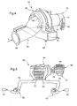
- FIG. 4 shows a air blower 52 comprising a support device 10 similar to that of Figures 1 to 3 housing internally a motor-turbine assembly similar to that previously described to thus constitute a motor-fan unit.
- a motor-turbine assembly similar to that previously described to thus constitute a motor-fan unit.
- an inlet duct 54 which has an inlet opening 56 and an outlet opening 58, the latter being connected to the opening 46 of the volute.
- This inlet duct 54 is intended to convey a airflow as represented by the arrow A. This airflow is then accelerated tangentially by the turbine and evacuated through an outlet duct 60 which extends into the tangential direction of the volute. This airflow is evacuated in the direction of arrow B.
- the blower 52 of FIG. 4 can be used in particular to constitute a main blower, but especially a blower secondary, also called relay blower, of a vehicle heating, ventilation and / or air conditioning automobile.
- a blower secondary also called relay blower
- Such a relay pulsator is used most often for heating, ventilation and / or air conditioning rear seats of a passenger compartment of a motor vehicle and shall therefore be of a small footprint, while providing a efficient cooling of its electric motor.
- FIG. 5 shows a heating apparatus 62, ventilation and / or air conditioning of a motor vehicle including an air handling unit designated in its together by the reference 64.
- This housing 64 lodges internally at least one heating radiator and possibly one air conditioning evaporator to provide a flow of air to temperature adjusted to be sent then in the passenger compartment of a motor vehicle.
- the housing 64 is powered from a blower principal 66 which is carried out according to the teachings FIGS. 1 to 4.
- This blower 66 comprises a support 10 analogous to that described above and connected to a input interface 68 to admit, in the support, outside air taken from the passenger compartment of the motor vehicle, ie recirculated air taken from inside the cabin, a mixture of these two flows of air, and this in a manner known in itself.
- the airflow is then sent into the housing by an inlet conduit 70.
- the air treatment housing 64 has two outlets 72 intended to send treated air to different regions the passenger compartment, for example to the rear seats of the vehicle.
- the two outlets 72 are connected by ducts 74 with two relay pulsators 52 similar to that of the figure 4.
- These two relay blowers are intended to send air treated to two respective nozzles 76 placed in locations chosen inside the cockpit. In the example, these nozzles open at the rear seats of the passenger compartment, on the right and left sides, respectively.
- the respective electric motors of the main blower 66 and relay pulsers 52 are each cooled by cooling means of the type described with reference to Figures 1 to 3.
- the invention makes it possible to control the flow rate of engine cooling air flow. So, in the case of a relay pulsator 52, the electric motor of this last will preferably have a consumption less than 120 Watts. In this case, the engine support device preferably have circular holes diameter will be less than or equal to 4 mm.
- the invention is susceptible of numerous variations, in particular as regards the number, position and dimensions of holes in the wall bottom of the support device.
- the invention finds a preferential application to heating, ventilation and / or air conditioning motor vehicles.
Landscapes
- Engineering & Computer Science (AREA)
- Power Engineering (AREA)
- Mechanical Engineering (AREA)
- Physics & Mathematics (AREA)
- Thermal Sciences (AREA)
- General Engineering & Computer Science (AREA)
- Structures Of Non-Positive Displacement Pumps (AREA)
Applications Claiming Priority (2)
| Application Number | Priority Date | Filing Date | Title |
|---|---|---|---|
| FR0310649 | 2003-09-10 | ||
| FR0310649A FR2859579B1 (fr) | 2003-09-10 | 2003-09-10 | Dispositif pour le support d'un moteur electrique entrainant une turbine, en particulier pour un appareil de chauffage, ventilation et/ou climatisation de vehicule automobile |
Publications (1)
| Publication Number | Publication Date |
|---|---|
| EP1515416A1 true EP1515416A1 (de) | 2005-03-16 |
Family
ID=34130786
Family Applications (1)
| Application Number | Title | Priority Date | Filing Date |
|---|---|---|---|
| EP04019384A Withdrawn EP1515416A1 (de) | 2003-09-10 | 2004-08-16 | Halteeinrichtung für einen ein Lüfterrad antreibenden elektrischen Motor, insbesonders für ein Heizungs-,Lüftungs- und/oder Klimagerät eines Kraftfahrzeuges |
Country Status (3)
| Country | Link |
|---|---|
| US (1) | US20050053495A1 (de) |
| EP (1) | EP1515416A1 (de) |
| FR (1) | FR2859579B1 (de) |
Cited By (5)
| Publication number | Priority date | Publication date | Assignee | Title |
|---|---|---|---|---|
| EP1850012A1 (de) * | 2006-04-28 | 2007-10-31 | Aldes Aeraulique | Belüftungsvorrichtung |
| FR2908482A1 (fr) * | 2006-11-13 | 2008-05-16 | Airfan Soc Par Actions Simplif | Appareil de delivrance regulee d'un gaz notamment appareil d'assistance respiratoire |
| WO2008148443A1 (de) * | 2007-06-08 | 2008-12-11 | Gm Global Technology Operations, Inc. | Gebläse für ein kraftfahrzeug |
| EP3163091A1 (de) * | 2015-10-29 | 2017-05-03 | Valeo Systemes Thermiques | Motoraufhängungsanordnung und entsprechende anlage zum heizen, belüften und/oder klimatisieren für kraftfahrzeug |
| US11621611B2 (en) | 2019-12-20 | 2023-04-04 | Borgwarner Inc. | Electric machine with baffle member for filtering air flow |
Families Citing this family (9)
| Publication number | Priority date | Publication date | Assignee | Title |
|---|---|---|---|---|
| EP2165078B1 (de) * | 2007-06-25 | 2010-10-27 | Airfan | Vorrichtung für geregelte gasabgabe, im besonderen für ein atemgerät |
| US8267674B2 (en) * | 2010-02-04 | 2012-09-18 | Robert Bosch Gmbh | Centrifugal blower assembly |
| DE102011088074A1 (de) * | 2011-12-09 | 2013-06-13 | BSH Bosch und Siemens Hausgeräte GmbH | Lüftervorrichtung, Haushaltsgerät sowie Verfahren zum Kühlen eines Motors einer Lüftervorrichtung |
| FR2984810B1 (fr) * | 2011-12-23 | 2015-06-19 | Valeo Systemes Thermiques | Dispositif de refroidissement par air d'un pulseur pour appareil de chauffage, de ventilation et de climatisation |
| US11407283B2 (en) | 2018-04-30 | 2022-08-09 | Tiger Tool International Incorporated | Cab heating systems and methods for vehicles |
| US11993130B2 (en) | 2018-11-05 | 2024-05-28 | Tiger Tool International Incorporated | Cooling systems and methods for vehicle cabs |
| CN112524061A (zh) * | 2019-09-19 | 2021-03-19 | 日本电产株式会社 | 送风装置和机电设备 |
| US11725667B2 (en) * | 2019-12-30 | 2023-08-15 | Cnh Industrial America Llc | Air source system of an agricultural system |
| US12030368B2 (en) | 2020-07-02 | 2024-07-09 | Tiger Tool International Incorporated | Compressor systems and methods for use by vehicle heating, ventilating, and air conditioning systems |
Citations (4)
| Publication number | Priority date | Publication date | Assignee | Title |
|---|---|---|---|---|
| FR2196681A5 (de) * | 1972-08-18 | 1974-03-15 | Gen Signal Corp | |
| EP0053703A2 (de) * | 1980-12-05 | 1982-06-16 | Honeywell Inc. | Kühlvorrichtung für Ventilatormotor |
| US4470753A (en) * | 1979-09-28 | 1984-09-11 | Suddeutsche Kuhlerfabrik Julius Fr. Behr Gmbh & Co. Kg | Radial blower, especially for heaters or air conditioning systems in vehicles |
| US5352099A (en) * | 1992-12-14 | 1994-10-04 | Ametek, Inc. | Exhaust fan for water heater |
-
2003
- 2003-09-10 FR FR0310649A patent/FR2859579B1/fr not_active Expired - Fee Related
-
2004
- 2004-08-16 EP EP04019384A patent/EP1515416A1/de not_active Withdrawn
- 2004-09-08 US US10/936,136 patent/US20050053495A1/en not_active Abandoned
Patent Citations (4)
| Publication number | Priority date | Publication date | Assignee | Title |
|---|---|---|---|---|
| FR2196681A5 (de) * | 1972-08-18 | 1974-03-15 | Gen Signal Corp | |
| US4470753A (en) * | 1979-09-28 | 1984-09-11 | Suddeutsche Kuhlerfabrik Julius Fr. Behr Gmbh & Co. Kg | Radial blower, especially for heaters or air conditioning systems in vehicles |
| EP0053703A2 (de) * | 1980-12-05 | 1982-06-16 | Honeywell Inc. | Kühlvorrichtung für Ventilatormotor |
| US5352099A (en) * | 1992-12-14 | 1994-10-04 | Ametek, Inc. | Exhaust fan for water heater |
Cited By (11)
| Publication number | Priority date | Publication date | Assignee | Title |
|---|---|---|---|---|
| EP1850012A1 (de) * | 2006-04-28 | 2007-10-31 | Aldes Aeraulique | Belüftungsvorrichtung |
| FR2900449A1 (fr) * | 2006-04-28 | 2007-11-02 | Aldes Aeraulique Sa | Dispositif de ventilation |
| FR2908482A1 (fr) * | 2006-11-13 | 2008-05-16 | Airfan Soc Par Actions Simplif | Appareil de delivrance regulee d'un gaz notamment appareil d'assistance respiratoire |
| WO2008059341A1 (en) * | 2006-11-13 | 2008-05-22 | Airfan | Apparatus for delivering a regulated supply of a gas, particularly respiratory assistance apparatus |
| US8096783B2 (en) | 2006-11-13 | 2012-01-17 | Air Liquide Medical Systems S.A. | Apparatus for delivering a regulated supply of a gas, particularly respiratory assistance apparatus |
| WO2008148443A1 (de) * | 2007-06-08 | 2008-12-11 | Gm Global Technology Operations, Inc. | Gebläse für ein kraftfahrzeug |
| RU2462370C2 (ru) * | 2007-06-08 | 2012-09-27 | Джи Эм Глоубал Текнолоджи Оперейшнз, Инк. | Вентилятор для автомобиля |
| DE102007026611B4 (de) * | 2007-06-08 | 2014-05-08 | GM Global Technology Operations LLC (n. d. Ges. d. Staates Delaware) | Gebläse für ein Kraftfahrzeug |
| EP3163091A1 (de) * | 2015-10-29 | 2017-05-03 | Valeo Systemes Thermiques | Motoraufhängungsanordnung und entsprechende anlage zum heizen, belüften und/oder klimatisieren für kraftfahrzeug |
| FR3043180A1 (fr) * | 2015-10-29 | 2017-05-05 | Valeo Systemes Thermiques | Ensemble support moteur et installation de chauffage, de ventilation et/ou de climatisation pour vehicule automobile correspondante |
| US11621611B2 (en) | 2019-12-20 | 2023-04-04 | Borgwarner Inc. | Electric machine with baffle member for filtering air flow |
Also Published As
| Publication number | Publication date |
|---|---|
| US20050053495A1 (en) | 2005-03-10 |
| FR2859579A1 (fr) | 2005-03-11 |
| FR2859579B1 (fr) | 2006-03-03 |
Similar Documents
| Publication | Publication Date | Title |
|---|---|---|
| EP3077678B1 (de) | Saugimpulsgeber für heizungs-, klima- und lüftungstechnische vorrichtung eines kraftfahrzeugs | |
| FR2859579A1 (fr) | Dispositif pour le support d'un moteur electrique entrainant une turbine, en particulier pour un appareil de chauffage, ventilation et/ou climatisation de vehicule automobile | |
| EP3857149B1 (de) | Wärmetauschermodul für automobile | |
| FR3045741A1 (fr) | Pulseur d'aspiration destine a un dispositif de chauffage, ventilation et/ou climatisation d'un vehicule automobile et dispositif de chauffage, ventilation et/ou climatisation | |
| FR2735426A1 (fr) | Dispositif de chauffage-ventilation et/ou de climatisation de l'habitacle d'un vehicule automobile | |
| FR2466648A1 (fr) | Ventilateur radial, notamment pour installation de chauffage ou de climatisation de vehicules | |
| EP3652007B1 (de) | Gebläse und entsprechende heizungs-, lüftungs- oder klimaanlage für ein kraftfahrzeug | |
| EP2889168B1 (de) | Vorrichtung zum Heizen, Belüften und/oder Klimatisieren | |
| FR3032917A1 (fr) | Module de conditionnement d'air d'un habitacle de vehicule automobile | |
| FR3072054B1 (fr) | Boitier d'entree d'air, et pulseur d'aspiration et dispositif de chauffage, ventilation et/ou climatisation pour vehicule automobile correspondants | |
| FR2786437A1 (fr) | Dispositif de chauffage et/ou climatisation de vehicule automobile, avec groupe moto-ventilateur compact | |
| EP1308631B1 (de) | Motorlüfter | |
| EP1800917B1 (de) | Fahrzeug-Klimaanlage mit einer demontierbaren Gebläseeinheit | |
| EP3737572B1 (de) | Lufteinlassgehäuse und gebläse für eine entsprechende heizungs-, lüftungs- und/oder klimatisierungsvorrichtung eines kraftfahrzeugs | |
| WO2003038281A1 (fr) | Groupe moto-ventilateur | |
| FR3095162A1 (fr) | Groupe moto-ventilateur d’un pulseur d’air d’un véhicule automobile | |
| FR2793737A1 (fr) | Dispositif de chauffage et/ou climatisation d'un vehicule automobile comprenant un groupe moto-ventilateur demontable | |
| EP2102970B1 (de) | Motorgetriebene lüftereinheit mit verbesserter kühlung | |
| FR2875560A1 (fr) | Ventilateur centrifuge a bruit reduit pour systeme de ventilation d'un vehicule automobile | |
| FR3133661A1 (fr) | Groupe motorisé de ventilation | |
| EP4058312B1 (de) | Heizungs-, lüftungs- und/oder klimatisierungsvorrichtung für ein kraftfahrzeug | |
| FR3087709A1 (fr) | Dispositif de chauffage, ventilation et/ou climatisation pour vehicule automobile | |
| FR3022987B1 (fr) | Dispositif de generation d'un flux d'air | |
| FR3014027A1 (fr) | Installation de chauffage, ventilation et/ou climatisation pour habitacle de vehicule automobile | |
| WO2015197306A1 (fr) | Dispositif de generation d'un flux d'air |
Legal Events
| Date | Code | Title | Description |
|---|---|---|---|
| PUAI | Public reference made under article 153(3) epc to a published international application that has entered the european phase |
Free format text: ORIGINAL CODE: 0009012 |
|
| AK | Designated contracting states |
Kind code of ref document: A1 Designated state(s): AT BE BG CH CY CZ DE DK EE ES FI FR GB GR HU IE IT LI LU MC NL PL PT RO SE SI SK TR |
|
| AX | Request for extension of the european patent |
Extension state: AL HR LT LV MK |
|
| 17P | Request for examination filed |
Effective date: 20050805 |
|
| AKX | Designation fees paid |
Designated state(s): AT BE BG CH CY CZ DE DK EE ES FI FR GB GR HU IE IT LI LU MC NL PL PT RO SE SI SK TR |
|
| 17Q | First examination report despatched |
Effective date: 20061030 |
|
| STAA | Information on the status of an ep patent application or granted ep patent |
Free format text: STATUS: THE APPLICATION IS DEEMED TO BE WITHDRAWN |
|
| 18D | Application deemed to be withdrawn |
Effective date: 20070510 |