EP1515593A1 - Procédé et dispositif de configuration d'un dispositif de contrôle d'équipements - Google Patents
Procédé et dispositif de configuration d'un dispositif de contrôle d'équipements Download PDFInfo
- Publication number
- EP1515593A1 EP1515593A1 EP04077515A EP04077515A EP1515593A1 EP 1515593 A1 EP1515593 A1 EP 1515593A1 EP 04077515 A EP04077515 A EP 04077515A EP 04077515 A EP04077515 A EP 04077515A EP 1515593 A1 EP1515593 A1 EP 1515593A1
- Authority
- EP
- European Patent Office
- Prior art keywords
- control device
- data
- equipment
- remote control
- command
- Prior art date
- Legal status (The legal status is an assumption and is not a legal conclusion. Google has not performed a legal analysis and makes no representation as to the accuracy of the status listed.)
- Granted
Links
Images


Classifications
-
- H—ELECTRICITY
- H04—ELECTRIC COMMUNICATION TECHNIQUE
- H04L—TRANSMISSION OF DIGITAL INFORMATION, e.g. TELEGRAPHIC COMMUNICATION
- H04L41/00—Arrangements for maintenance, administration or management of data switching networks, e.g. of packet switching networks
- H04L41/08—Configuration management of networks or network elements
- H04L41/0803—Configuration setting
- H04L41/0813—Configuration setting characterised by the conditions triggering a change of settings
- H04L41/082—Configuration setting characterised by the conditions triggering a change of settings the condition being updates or upgrades of network functionality
-
- G—PHYSICS
- G08—SIGNALLING
- G08C—TRANSMISSION SYSTEMS FOR MEASURED VALUES, CONTROL OR SIMILAR SIGNALS
- G08C19/00—Electric signal transmission systems
- G08C19/16—Electric signal transmission systems in which transmission is by pulses
- G08C19/28—Electric signal transmission systems in which transmission is by pulses using pulse code
-
- G—PHYSICS
- G08—SIGNALLING
- G08C—TRANSMISSION SYSTEMS FOR MEASURED VALUES, CONTROL OR SIMILAR SIGNALS
- G08C2201/00—Transmission systems of control signals via wireless link
- G08C2201/20—Binding and programming of remote control devices
Definitions
- the present invention relates to a method and a device for configuring a equipment control device.
- the invention applies to the field of remote control of electrical equipment from a remote control generating at least one frame data to an electrical equipment control device for enable or disable electrical equipment or put electrical equipment into a predetermined state.
- state a configuration of an equipment in a state predefined, for example lighting according to a given power, an opening partial or total shutters, the setting in operation of a heating in a particular mode of operation, the configuration of a central alarm according a predefined operating mode.
- This predetermined state is predefined previously by the user of such a system.
- the automatisms commonly used in the building implement control and actuation devices which after a setting configuration, allow to fulfill several functions, such as, for example, a command lighting or heating or ascent and descent of shutters.
- Each device actuating device comprises an encoder wheel making it possible to define an identifier at actuating device.
- the radio remote control generating a signal comprising an identifier, controls the devices for actuating electrical equipment having the same identifier.
- the radio remote control allows controls such as control and remote dimming of a light, the remote control of a gate and / or a garage door.
- radio remotes do not allow the setting in a predetermined state electrical equipment following a single or simple action on the remote control. Indeed, the user of such radio remotes can not remotely control putting the electrical equipment in a predetermined state because such systems do not are not able to memorize such states. The user must therefore, by pressing the different keys on the remote control, whenever it wishes, electrical equipment in the state he desires. These systems are thus unattractive and require a significant number of user manipulations.
- control systems of actuating devices electrical equipment from a controller consisting of a computer and a particular software.
- each electrical equipment control device has a particular address and the controller transmits on the electricity supply network a command to the address of the electrical equipment control device that one wants to control. Only the electrical equipment control device having the same address executes the command. If several actuators electrical equipment have the same address, each of the modules will perform the ordered.
- this system it is possible to program a set of commands that allows for example, when the user returns home, to turn on the light outside, the light of the entrance and the living room of his home while commanding the heating in a comfort mode, or to define, when the user is absent, sequences of opening or closing shutters simulating the presence of the user at his home.
- This type of system has a number of problems.
- the user such a system must have a computer, which increases all the more the cost of such a system.
- this system is not flexible and not adapted to the different scenarios that wants to perform each person living in the same home.
- the object of the invention is to solve the disadvantages of the prior art by proposing a method of configuring an equipment control device, the device control device being inter alia controlled by a device of remote control characterized in that the method comprises the steps, performed at level of the equipment control device, setting into a configuration mode the control device, receiving at least one data frame generated by the remote control device, the data frame comprising at least one identifier associated with the control device and information representative of the type of command generated by the remote control and storage device the identifier associated with the control device and representative information the type of command generated by the remote controller.
- the invention proposes an equipment control device, the device control device being inter alia controlled by a device of remote control characterized in that the equipment control device comprises means for setting the control device in a mode of configuration, means for receiving at least one data frame generated by the remote control device, the data frame comprising at least one identifier associated with the control device and information representative of the type of command generated by the remote control device and means of storing the identifier associated with the control device and information representative of the type of command generated by the remote controller.
- control device receiving and memorizing the identifier associated with the control device and information representative of the type of command generated by the remote control device is then able to process different types of orders.
- the type of command generated by the controller remote is representative of the number of keys associated with said command.
- a single key of the control device is associated with a command to control the control of the equipment in a state predetermined.
- the equipment is an electrical equipment and the device control modifies the electrical energy delivered to the electrical equipment for control said electrical equipment.
- the user of such a system by adjusting the amount of energy delivered to electrical equipment and generating at least one frame of data per via a key press of the remote control device, assigns in a simple way a predetermined state to the electrical equipment with each support on the remote control device key.
- each data frame further comprises a subscript representative of a command from a set of commands of the same type as the remote control device is able to generate and that the index is also stored.
- control devices grouping several orders of the same type while allowing the control device to differentiation.
- the predetermined state is the state of the equipment during the configuration of the control device and in that information representative of the condition of the electrical equipment when configuring the control device are stored.
- the received data frame is a radio frame.
- the user can control the control device of another room than that in which the control device is located.
- At least one signaling means is activated when the control device is in the configuration mode.
- the user receives a confirmation of the setting of the control device in the configuration mode.
- the equipment control device is put into a mode control of the equipment following the storage of the data included in the received frame or data included in a received frame and information representative of the state of the electrical equipment during the configuration of the control device.
- the existence is determined among the previously stored data of data identical to the data included in a received frame, data included in the received frame or data included in the received frame and information representative of the state of the electrical equipment during the configuration of the control device, in a separate memory area of each memory zone comprising the previously stored data if it does not exist from previously stored data of data identical to the data included in the received frame and if it exists among the data previously memorized data identical to the data included in the received frame, stores data included in the received frame or data included in the received frame and information representative of the state of the electrical equipment during the configuration of the control device in the memory area including the identical data previously stored.
- control a device for controlling a device with several control devices.
- control devices such as remote controls
- each individual of the same family can order the devices according to his own wishes.
- Each individual having of a command can then put using this remote several devices in the predetermined state that it will have previously configured.
- the invention also relates to a method for controlling equipment by a control device, the control device being inter alia controlled by the minus a remote control device characterized in that the method comprises the steps, performed by the control device, of receiving at least one frame data generated by a remote controller, the data frame comprising at least one identifier associated with the control device and information representative of the type of command generated by the device of remote control, determination of existence among the data previously stored data identical to a part of the data included in the frame received with at least the identifier and if identical data exist, control of the equipment based on information associated with the data identical to the part of the data included in the received frame, the information being representative of a state of the equipment or control of the equipment according to another part of the data included in the frame received.
- the invention proposes a device control device, the control device being inter alia controlled by at least one remote control characterized in that the control device comprises means receiving at least one data frame generated by a controller remote, the data frame comprising at least one identifier associated with the device command and information representative of the type of command generated by the remote control device, means for determining the existence among the previously stored data of data identical to a part of the data included in the received frame including at least the identifier and means of control of the equipment based on information associated with the data identical to the part of the data included in the received frame, the information being representative of a state of the equipment, or according to a other part of the data included in the received frame.
- the invention also relates to a control method of a control device by a remote control device, the control device controlling a electrical equipment, characterized in that the method comprises the steps, performed by the remote control device, for detecting at least one press on at least one key of the remote control device and transfer of at least one data frame comprising at least one identifier associated with the device of command and information representative of the type of command generated by the remote control device.
- the invention proposes a remote control device of a control device of an electrical equipment, characterized in that the device for remote control comprises means for detecting at least one press on the least one touch of the remote control device and transfer means from least one data frame comprising at least one identifier associated with the device command and information representative of the type of command generated by the remote control device.
- the invention also relates to the computer program stored on a medium information, the program including instructions for carrying out the previously described method, when it is loaded and executed by a system computer science.
- Fig. 1 represents a network for configuring and controlling devices actuating electrical equipment.
- the network 100 of FIG. 1 is a home automation network of a dwelling by example. This network 100 allows a user to configure control 10a and 10b of equipment 13a and 13b and operate equipment 13a and 13b via control devices 15a, 15b and 15c and devices control 10a and 10b.
- the equipment 13a and 13b are, for example, heating equipment, monitoring equipment or electrical equipment such as equipment lighting, shutters or any type of electrical equipment that can be controlled by the control device by modifying the electrical energy delivered to the audit electrical equipment. It should be noted that any type of equipment can be controlled by the present invention.
- control devices are preferably remote controls, and could also be presence sensors, brightness or sound sensors.
- FIG. 1 For the sake of simplification, a limited number of remote controls 15, control devices 10 and equipment such as electrical equipment 13 are represented in FIG. 1. Of course, the invention as described is suitable for operate with a smaller or larger number of remote controls 15, control devices 10 and electrical equipment 13.
- remote controls 15a, 15b and 15c are provided for control the control devices 10a and 10b.
- Each remote control 15 has a respective unique identifier. This identifier is for example stored in each remote control 15 during the manufacture thereof.
- Each remote control 15 also includes information representative of the type of command generated by the remote control 15. These commands are for example commands of type activation / deactivation of a electrical equipment 13 via two keys of the device of command 15 or a command to put an electrical equipment in a state predetermined predetermined by the user of the network 100 and this by via a single key of the control device 15.
- Each remote control furthermore includes an index associated with each command of the 15. This index is thus representative of one of a set of commands that the remote control 15 is able to generate. He is at note that if the remote control 15 has only one key, a subscript may not be associated with the remote control button.
- the remote controls 15a, 15b and 15c are remote controls capable of transmitting radio data frames for equipment control devices. It should be noted that remote controls 15 can also transmit frames of data in infrared form, on a wired network independent of the network of supply of electrical energy to the dwelling in which the invention is implemented or on the electricity supply network of the dwelling according to the technique of carrier currents. Remote controls 15 may be movable control devices, that is to say be in the form of housing that the user is likely to move into the dwelling. Remote controls 15 can also be integrated in the partitions of the house.
- the remote control 15a has a single key 16a.
- the remote control 15a is a remote control capable of controlling control devices 10 to put one or more equipment in a predetermined state.
- the remote control 15a has an identifier denoted Id1, information indicating that the command is an order placing equipment in a state predetermined AND and an index associated with the command noted I1.
- the remote control 15a transmits, following the pressing of the key 16a by the user, a radio data frame for the control devices 10a and 10b.
- the transmission of this frame is represented by the arrows 18a and 18b.
- This frame comprises the identifier denoted ID1, the information AND and the index I1.
- the data frame may further comprise a Boolean value representative of pressing the key 16a.
- control device 15a is a sensor, the latter at the detection of a predetermined event generates the same type of data frame as that previously described.
- the remote control 15b has two keys marked 16b and 16c.
- the remote control 16b is a remote control capable of controlling 10 devices control according to activation / deactivation commands of electrical equipment.
- the type of command generated by the remote control is a two-way keys.
- the remote control 15b has an identifier denoted Id2, information indicating that the command is a noted activation or deactivation command T2T and an index noted I1 associated with the command.
- the remote control 15b transmits, following the pressing of the key 16b by the user, a radio data frame including the identifier ID2, the information T2T and the index I1, for the control devices 10a and 10b.
- the transmission of this frame is represented by the arrows 18c and 18d.
- the 16b key allows for example the activation of an electrical device, or to be by example a command for the activation of the ascent of a shutter or the increase in electrical energy delivered to lighting equipment.
- the remote control 15b transmits, following the pressing of the key 16c by the user, a radio data frame including the identifier ID2, the information T2T and the index 12, for the control devices 10a and 10b.
- the transmission of this frame is represented by the arrows 18c and 18d.
- the 16c button allows for example the deactivation of an electrical device, or to be for example a command for the activation of the descent of a shutter or the reduction of electrical energy delivered to lighting equipment.
- each transmitted data frame also includes two Boolean information representative of the supports on the keys of the remote control 15b.
- the frame of data thus includes the binary information 0 and 1 representative of the non-support on the key 16b and a key on the key 16c.
- the remote control 15c is a remote control capable of controlling a plurality equipment and allows the generation of different types of commands.
- the remote control 15c has a screen 17 able to display messages representative of commands generated by the user of the remote control 15c continued at a touch of a key.
- the remote control 15c comprises for example six keys 16d to 16i.
- the 16d and 16e are, according to this example, buttons associated with a command to activate / deactivate an electrical equipment.
- the 16f and 16g keys are also keys associated with a command to activate / deactivate a device electric.
- each 16h or 16i key is a key associated with a command for controlling the control of a device in a predetermined state.
- the remote control 15c transmits, following the pressing of a key 16d or 16e by the user, a radio data frame including the identifier Id3, the information T2T, the index I1 associated with the command and two Boolean information representative of a support on one or the keys 16d or 16e.
- the remote control 15c transmits, following the pressing of a key 16f or 16g by the user, a radio data frame including the identifier Id3, the information T2T, the index I2 associated with the command and two Boolean information representative of a press on one or the keys 16f or 16g.
- the remote control 15c transmits, following the pressing of the key 16h by the user, a radio data frame including the identifier ID3, the information AND, and the index I3 associated with the command to control the control of a equipment in a predetermined state.
- the remote control 15c transmits, following the pressing of the key 16i by the user, a radio data frame including the identifier ID3, the information AND, and the index I4 associated with the command to control the control of a equipment in a predetermined state.
- the control device 10a is placed between the power distribution network 14 electrical housing and 13a electrical equipment.
- the control device 10a comprises for example two keys denoted 11a and 11b.
- the key 11a allows for example the activation of the electrical apparatus 13a, or is for example a command for the activation of the rise of a shutter or the increase in electrical energy delivered to lighting equipment.
- the 11b key allows for example the deactivation of the electrical apparatus 13a, or is for example a command for the activation of the descent of a shutter or the reduction of electrical energy delivered to lighting equipment.
- the keys 11a and 11b in a so-called control mode make it possible to modify the electrical energy delivered to the electrical equipment 13a.
- a simultaneous pressing on the keys 11a and 11b causes the setting of the control device 10a in a configuration mode. This will be described in more detail with reference to FIG. 3.
- the control device 10a comprises a signaling means 12a, by example a light-emitting diode that flashes when the control device 10a is in the configuration mode.
- a signaling means 12a by example a light-emitting diode that flashes when the control device 10a is in the configuration mode.
- the light-emitting diode can be associated or replaced by an electroacoustic transducer that generates a audible signal when the control device 10a is in the configuration mode.
- the control device 10a is configured to perform actions following the receiving frames from the control devices 15a and 15b.
- the device control 10a has in memory the identifier ID1, the information AND, the index I1 as well as an associated state value denoted Val.
- the control device 10a comprises also in memory the identifier ID2, the information T2T, the index I1 associated with this ordered. Configuration and storage of this data will be described more in detail in FIG. 3.
- the control device 10b is placed between the power distribution network 14 electrical housing and 13b electrical equipment.
- the keys 11c and 11d have a function similar to the keys 11a and 11b. They will not be more described.
- the signaling means 12b has a similar function by means of signaling 12a. He will not be more described.
- the control device 10b is for example configured to perform actions following the reception of frames from the control devices 15a and 15c.
- the control device 10b has in its memory the identifier ID1, the information AND, the index I1, as well as an associated state value denoted Val.
- the device control 10b also has in its memory the identifier ID3, the information T2T and the index I1 for controlling the activation of the electrical equipment 13b.
- the control device 10b also has in its memory the identifier ID3, the information AND, the index I3 associated with the command of the key 16i making it possible to control the putting in a predetermined state of the electrical equipment 13b.
- Fig. 2 shows a schematic view of an electrical equipment control device.
- the electrical equipment control device 10b is identical to the electrical equipment control device 10a, only the control device 10a will be described.
- the electrical equipment control device 10a consists of a controller 20 adapted to read and / or store data in a memory 21, to control the power supply module 22 of the electrical equipment 13a, the keyboard consisting of at least two keys 11a and 11b, the information means 24 consisting of the light-emitting diode 12a, and a radio interface connected to a Antenna 26 for receiving data frames from the remote controls 15.
- the antenna 26 and the interface 25 are replaced by sensors and an interface corresponding to the medium used.
- elements 20 to 25 can be integrated in one or several dedicated or programmed components.
- the memory 21 stores, among other things, the identifiers, the information representative of the type of command generated by the remote controls for which the control device 10a has been configured to perform actions following the receiving a data frame generated by these remote controls.
- control device comprises a controller capable of execute the program instructions corresponding to the algorithms such as described in FIGS. 3 and 4.
- the instructions are stored in the memory 21.
- control device 10a is produced using components electronic devices operating according to a state diagram in accordance with the algorithms that described later in FIGS. 3 and 4.
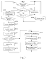
- Fig. 3 represents an algorithm for configuring a control device of equipment executed by an equipment control device.
- the controller 20 of the equipment control device 10a reads from the memory 21 the instructions of the program corresponding to steps E300 to E316 of FIG. 3 and the loads in RAM not shown to execute them.
- the controller 20 of the control device 10a periodically executes the steps E300 to E316 of the algorithm of FIG. 3.
- step E300 the controller 20 waits for pressing on at least one key 11a or 11b of the control device 10a.
- step E301 consists in determining whether the control device 10a must pass in the configuration mode or not.
- simultaneous pressing on the keys 11a and 11b is representative of the passage in the configuration mode.
- the controller 20 goes to the stage following E302.
- the controller 20 checks whether the increment key, for example the key 11a has been pressed. If so, the controller 20 increments at step E303 the variable denoted Val of a unit and transfers this variable to the module power supply 22 so that it increases the electrical energy delivered a the electrical equipment 13a.
- step performed the controller 20 returns to step E300 previously described waiting for a new action on the keyboard 23 of the control device or to check whether the key 11a is still actuated.
- steps E300 to E303 are performed in the same manner as previously described.
- step E304 the variable denoted Val of a unit and transfers this variable to the module power supply to reduce the electrical energy delivered to the equipment electric 13a.
- step performed the controller 20 returns to step E300 previously described waiting for a new action on the keyboard 23 of the control device or to check if the key 11b is still pressed.
- steps E300 to E304 are performed in the same manner as previously described.
- step E305 If both keys 11a and 11b are simultaneously pressed, the controller 20 go to step E305.
- the information means 24 is activated.
- This activation corresponds for example the flashing of a light-emitting diode or the activation of a electroacoustic transducer so that it generates a sound signal.
- step E306 which consists in waiting for the reception of a data frame of a device of control 15 and this through the antenna 26 and the radio interface 25.
- controller 20 Upon receipt of a data frame, controller 20 proceeds to step E307.
- the controller 20 If no data frame is received at this stage and this for a while predetermined for example equal to three minutes, the controller 20 returns to step E300 previously described by deactivating the information means 24.
- step E307 the controller 20 reads, in the received data frame, the identifier from the remote control that sent the data frame.
- the frame of data is transmitted by the remote control 15b.
- the identifier is therefore at the value Id2.
- step E308 the controller 20 reads in the data frame the information representative of the type of command generated by the device of remote control, in this case, the remote control 15b.
- the identifier is at the value T2T.
- step E309 the controller 20 reads in the data frame the index I1 associated with the order.
- the controller 20 checks at step E310 whether the information representative of the type of command generated by the device of remote control, in this case, the remote control 15b are information control representative for placing the equipment 13a in a state predetermined. This is done by comparing this information to an AND constant representative of this state.
- the controller 20 then switches to the next step E313.
- step E313 the identifier Id2 read in step E307.
- the controller 20 stores in step E314 the T2T information representative of the type of command generated by the remote control 15b read at step E308.
- step E315 the index I1 read in step E309. Finally, the controller 20 deactivates the information means 24 and returns to step E300.
- control device 10a has been associated with the remote control 15b.
- control device 10a will execute the command associated with pressing the key.
- control device 10b has not been put also in the configuration mode, no association exists between the device of control 10b and the remote control 15b.
- the user has pressed the key 16a of the remote control 15a.
- step E307 the controller 20 reads in the data frame the identifier Id1 of the remote control 15a having sent the data frame.
- step E308 the controller 20 reads in the data frame the information AND representative of the type of command generated by the remote control 15a.
- step E309 the controller 20 reads in the data frame the index I1 of the order.
- the controller 20 checks at step E310 whether the information representative of the type of command generated by the device of remote control, in this case, the remote control 15a are information representative of an order for placing the equipment in a state predetermined. According to our example, information representative of the type of command generated by the remote control 15a are equal to AND, the controller 20 passes then to the next step E311.
- the controller 20 reads the value of the variable Val representative of the energy delivered by the module 22 to the electrical equipment 13a.
- This variable Val is information representative of the state of the electrical equipment, the value of this variable having been defined previously in steps E300 to E303.
- the controller 20 then proceeds to the previously described steps E315 to E318 and thus memorizes, in association with the value of the variable Val, the identifier Id1 of the remote control 15a having transmitted the data frame, the information AND representative of the type of command generated by the remote control 15a and the index I1.
- control device 10a has been associated with the remote control 15a.
- the device control 10a will execute the command associated with pressing the key, that is to say the control for the control of electrical equipment in the state defined by the Val variable previously stored.
- the remote controls 15a and 15c associate with the device 10b in the same way as described above for the remote controls 15a and 15b.
- the indices associated with the commands allow the control device 10b to distinguish the commands generated by a press on the keys 16d or 16e commands generated by a key press 16f or 16g.
- the combination of the remote control 15a with the control devices 10a and 10b can also be performed with a single press on the key 16a of the remote control 15a if both devices 10a and 10b have been put into the configuration mode before pressing the key 15a.
- remote control 16b associated with the device of control 10a can be used to adjust the electrical energy delivered to the equipment 13a in the same manner as described in the steps E300 to E304 of the algorithm. The value of the variable Val is thus modified.
- the value of the variable Val can be defined following the step E310 by pressing one of the keys 11a or 11b of the control device 10a.
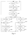
- Fig. 4 represents a control algorithm of a piece of equipment executed by a equipment control device.
- the controller 20 of the electrical equipment control device 10a reads from its memory 21 the instructions of the program corresponding to the steps E400 to E412 of FIG. 4 and loads them into RAM to execute them.
- This algorithm is carried out continuously by the control devices 10a and 10b when these are in a normal operating mode, ie both that the keys 11a and 11b, respectively 11c and 11d are not simultaneously supported.
- step E400 the controller 20 waits for the reception of a data frame of a control device and this, via the antenna 26 and the interface radio 25.
- controller 20 Upon receipt of a data frame, controller 20 proceeds to step E401.
- step E401 the controller 20 reads in the data frame the identifier of the remote control having sent the data frame.
- the data frame is emitted by the remote control 15c and is received by the control device 10a.
- the identifier is therefore Id3.
- step E402 the controller 20 checks in step E402 if the identifier Id3 is stored in memory 21.
- step E402 only Id1 and Id2 identifiers of remote controls 15a and 15b are stored.
- the test of step E402 is negative.
- the control device 10a not being associated with the remote control 15c, the latter does not process the received frame and returns to step E400 and waits for the reception of new frames.
- step E401 Upon receipt of a new frame, the controller 20 proceeds to step E401.
- step E401 the controller 20 reads in the data frame the identifier of the remote control having sent the data frame.
- the data frame is transmitted by the remote control 15b and is received by the control device 10a.
- the identifier is therefore at the value Id2.
- step E402 the test of step E402 is positive.
- the device 10a control is associated with the remote control 15b, it goes to step 403.
- step E403 the controller 20 reads in the received data frame the information representative of the type of command generated by the device of remote control, in this case, the remote control 15b.
- the identifier is at the value T2T.
- the controller 20 checks whether the information representative of the type of command generated by the remote control 15b are Representative control information of the equipment in a predetermined state. According to our example, the information representative of the type of command generated by the remote control 15b are equal to T2T, the controller 20 then goes to the stage following E405.
- the controller 20 reads in the data frame the index associated with the user operated control.
- the index is equal to I1.
- the controller 20 checks, at step E406, whether the index read is identical to the memorized index.
- a remote control such as the remote control 15c can have several commands of the same type. The index allows to differentiate these different commands.
- step E400 If the index is different, no action is performed, the controller 20 returns in step E400 waiting for a new frame.
- the controller 20 reads in the data frame two pieces of information Booleans representative of the presses on the keys of the remote control 15b.
- the data frame thus comprises the binary information 0 and 1 representative of the non-pressing on the key 16b and a press the key 16c.
- the processor 20 determines the command corresponding and controls, in step E408, the power supply module 22 so that it transfers all the electrical energy to the electrical equipment 13a according to the Boolean information read.
- the electrical energy transferred to the electrical equipment 13a is increased.
- step E400 the controller 20 returns to step E400 and waits for the receiving new frames.
- step E401 Upon receipt of a new frame, the controller 20 proceeds to step E401.
- step E401 the controller 20 reads in the data frame the identifier of the remote control having sent the data frame.
- the data frame is emitted by the remote control 15a and is received by the control device 10a.
- the identifier is therefore at the value Id1.
- step E402 The identifier Id1 being stored, the test of step E402 is positive.
- the device 10a control being associated with the remote control 15a, it goes to step 403.
- step E403 the controller 20 reads in the data frame the information representative of the type of command generated by the remote controller, in this case, the remote control 15a.
- the identifier is at the ET value.
- the controller 20 checks whether the information representative of the type of command generated by the remote control 15b are information representative of a command for the control of the apparatus 13a in a predetermined state. According to our example, information representative of the type of command generated by the remote control 15a are equal to AND, the controller 20 passes then to the next step E409.
- the controller 20 reads in the received data frame the associated index to the user-operated control.
- the index is equal to I1.
- the controller 20 checks, in step E410, whether the index read is identical to the memorized index.
- a remote control such as the remote control 15c can have several commands of the same type. The index allows to differentiate these different commands.
- step E400 If the index is different, no action is performed, the controller 20 returns in step E400 waiting for a new frame.
- the controller 20 goes to step E411.
- the controller 20 reads the value of the variable Val stored in association with the identifier Id1 and the index I1.
- the controller 20 controls at step E412 the module supply 22 for it transfers to the electrical equipment 13a the energy equivalent to the value of the variable Val previously read.
- controller 20 returns to step E400 and waits for receiving a new data frame.
- the controller 20 controls the means 22 so that the latter emits a visual and / or audible signal of account of the order. This is particularly interesting when for example the electrical apparatus ordered is defective. The user can thus determine certain way in which the control device or electrical device is defective.
Landscapes
- Engineering & Computer Science (AREA)
- Computer Networks & Wireless Communication (AREA)
- Signal Processing (AREA)
- Physics & Mathematics (AREA)
- General Physics & Mathematics (AREA)
- Selective Calling Equipment (AREA)
Abstract
Description
Claims (16)
- Procédé de configuration d'un dispositif de contrôle d'équipements pour l'association d'un dispositif de commande distant audit dispositif de contrôle d'équipements, caractérisé en ce que le procédé comporte les étapes, effectuées au niveau du dispositif de contrôle d'équipements, de :mise dans un mode de configuration du dispositif de contrôle,réception d'au moins une trame de données générée par un dispositif de commande distant, la trame de données comportant au moins un identifiant associé au dispositif de commande et des informations représentatives du type de commande générée par le dispositif de commande distant,mémorisation de l'identifiant associé au dispositif de commande et des informations représentatives du type de commande générée par le dispositif de commande distant pour associer le dispositif de commande distant au dispositif de contrôle d'équipements.
- Procédé selon la revendication 1, caractérisé en ce que le type de commande générée par le dispositif de commande distant est représentatif du nombre de touches associées à ladite commande.
- Procédé selon la revendication 2, caractérisé en ce qu'une unique touche du dispositif de commande est associée à ladite commande pour commander le contrôle de l'équipement dans un état prédéterminé.
- Procédé selon l'une quelconque des revendications 1 à 3, caractérisé en ce que l'équipement est un équipement électrique et en ce que le dispositif de contrôle modifie l'énergie électrique délivrée audit équipement électrique pour contrôler ledit équipement électrique.
- Procédé selon la revendication 4, caractérisé en ce que la ou chaque trame de données comporte en outre un indice représentatif d'une commande parmi un ensemble de commandes de même type que le dispositif de commande distant est apte à générer et en ce que l'indice est aussi mémorisé.
- Procédé selon la revendication 5, caractérisé en ce que l'état prédéterminé est l'état de l'équipement lors de la configuration du dispositif de contrôle et en ce que des informations représentatives de l'état de l'équipement électrique lors de la configuration du dispositif de contrôle sont mémorisées.
- Procédé selon la revendication 6, caractérisé en ce que le procédé comporte en outre une étape de mise du dispositif de contrôle d'équipements dans un mode de contrôle de l'équipement suite à la mémorisation des données comprises dans la trame reçue ou des données comprises dans une trame reçue et des informations représentatives de l'état de l'équipement électrique lors de la configuration du dispositif de contrôle.
- Procédé selon la revendication 6, caractérisé en ce que préalablement à la mémorisation des données comprises dans une trame reçue ou des données comprises dans une trame reçue et des informations représentatives de l'état de l'équipement lors de la configuration du dispositif de contrôle, le procédé comporte les étapes de :détermination de l'existence parmi les données précédemment mémorisées de données identiques aux données comprises dans une trame reçue,mémorisation des données comprises dans la trame reçue ou des données comprises dans la trame reçue et des informations représentatives de l'état de l'équipement électrique lors de la configuration du dispositif de contrôle, dans une zone mémoire distincte de chaque zone mémoire comprenant les données précédemment mémorisées s'il n'existe pas parmi des données précédemment mémorisées de données identiques aux données comprises dans la trame reçue,s'il existe parmi les données précédemment mémorisées des données identiques aux données comprises dans la trame reçue, mémorisation des données comprises dans la trame reçue ou des données comprises dans la trame reçue et des informations représentatives de l'état de l'équipement électrique lors de la configuration du dispositif de contrôle dans la zone mémoire comprenant les données identiques précédemment mémorisées.
- Procédé selon l'une quelconque des revendications 1 à 8, caractérisé en ce que la trame de données reçue est une trame radio.
- Procédé selon l'une quelconque des revendications 1 à 9, caractérisé en ce que le procédé comporte en outre une étape d'activation d'au moins un moyen de signalisation lorsque le dispositif de contrôle est dans le mode de configuration.
- Procédé de contrôle d'un équipement par un dispositif de contrôle, le dispositif de contrôle étant entre autres commandé par au moins un dispositif de commande distant, caractérisé en ce que le procédé comporte les étapes, effectuées par le dispositif de contrôle, de :réception d'au moins une trame de données générée par un dispositif de commande distant, la trame de données comportant au moins un identifiant associé au dispositif de commande et des informations représentatives du nombre de touches associées à la commande,détermination de l'existence parmi des données précédemment mémorisées de données identiques à une partie des données comprises dans la trame reçue comportant au moins l'identifiant,si des données identiques existent, contrôle de l'équipement en fonction du nombre de touches associées et d'informations associées aux données mémorisées identiques à la partie des données comprises dans la trame reçue, les informations étant représentatives d'un état de l'équipement ou contrôle de l'équipement en fonction du nombre de touches associées et d'une autre partie des données comprises dans la trame reçue.
- Procédé de commande d'un dispositif de contrôle par un dispositif de commande distant, le dispositif de contrôle contrôlant un équipement électrique, caractérisé en ce que le procédé comporte les étapes, effectuées par le dispositif de commande distant de :détection d'au moins un appui sur au moins une touche du dispositif de commande distant,transfert d'au moins une trame de données comportant au moins un identifiant associé au dispositif de commande et des informations représentatives du nombre de touches associées à la commande générée par le dispositif de commande distant.
- Procédé selon la revendication 12, caractérisé en ce que le type de commande générée par le dispositif de commande distant est représentatif du nombre de touches associées à ladite commande et en ce que la trame de données comporte en outre des informations sur chaque touche associée à ladite commande et un indice représentatif de la commande parmi l'ensemble de commandes de même type que le dispositif de commande distant est apte à générer.
- Dispositif de contrôle d'équipements apte à être associé à un dispositif de commande distant, caractérisé en ce que le dispositif de contrôle d'équipements comporte :des moyens de mise du dispositif de contrôle dans un mode de configuration,des moyens de réception d'au moins une trame de données générée par le dispositif de commande distant, la trame de données comportant au moins un identifiant associé au dispositif de commande et des informations représentatives du type de commande générée par le dispositif de commande distant,des moyens de mémorisation de l'identifiant associé au dispositif de commande et des informations représentatives du type de commande générée par le dispositif de commande distant pour associer le dispositif de commande distant au dispositif de contrôle d'équipements.
- Dispositif de contrôle d'équipements, le dispositif de contrôle d'équipements étant entre autres commandé par au moins un dispositif de commande distant, caractérisé en ce que le dispositif de contrôle d'équipements comporte :des moyens de réception d'au moins une trame de données générée par un dispositif de commande distant, la trame de données comportant au moins un identifiant associé au dispositif de commande et des informations représentatives du nombre de touches associées à la commande,des moyens de détermination de l'existence parmi les données précédemment mémorisées de données identiques à une partie des données comprises dans la trame reçue comportant au moins l'identifiant,des moyens de contrôle de l'équipement en fonction du nombre de touches associées et d'informations associées aux données mémorisées identiques à la partie des données comprises dans la trame reçue, les informations étant représentatives d'un état de l'équipement, ou en fonction du nombre de touches associées et d'une autre partie des données comprises dans la trame reçue.
- Dispositif de commande distant d'un dispositif de contrôle d'équipements électriques, caractérisé en ce que le dispositif de commande distant comporte :des moyens de détection d'au moins un appui sur au moins une touche du dispositif de commande distant,des moyens de transfert d'au moins une trame de données comportant au moins un identifiant associé au dispositif de commande et des informations représentatives du nombre de touches associées à la commande générée par le dispositif de commande distant.
Applications Claiming Priority (2)
| Application Number | Priority Date | Filing Date | Title |
|---|---|---|---|
| FR0310810A FR2859845B1 (fr) | 2003-09-15 | 2003-09-15 | Procede et dispositif de configuration d'un dispositif de controle d'equipements |
| FR0310810 | 2003-09-15 |
Publications (2)
| Publication Number | Publication Date |
|---|---|
| EP1515593A1 true EP1515593A1 (fr) | 2005-03-16 |
| EP1515593B1 EP1515593B1 (fr) | 2010-07-21 |
Family
ID=34130818
Family Applications (1)
| Application Number | Title | Priority Date | Filing Date |
|---|---|---|---|
| EP20040077515 Expired - Lifetime EP1515593B1 (fr) | 2003-09-15 | 2004-09-10 | Procédé et dispositif de configuration d'un dispositif de contrôle d'équipements |
Country Status (4)
| Country | Link |
|---|---|
| EP (1) | EP1515593B1 (fr) |
| DE (1) | DE602004028197D1 (fr) |
| ES (1) | ES2349253T3 (fr) |
| FR (1) | FR2859845B1 (fr) |
Cited By (2)
| Publication number | Priority date | Publication date | Assignee | Title |
|---|---|---|---|---|
| EP1947621A3 (fr) * | 2007-01-16 | 2009-08-19 | SMK Corporation | Système de communication RF |
| EP2784981A1 (fr) * | 2013-03-27 | 2014-10-01 | Somfy SAS | Programmation centralisée d'une installation domotique |
Citations (3)
| Publication number | Priority date | Publication date | Assignee | Title |
|---|---|---|---|---|
| EP0503699A1 (fr) * | 1991-02-27 | 1992-09-16 | Koninklijke Philips Electronics N.V. | Système pour régler des paramètres ambiants |
| EP0505699A1 (fr) | 1991-03-26 | 1992-09-30 | Bosch-Siemens HausgerÀ¤te GmbH | Dispositif de support pour tenir un objet lors de son émaillage par immersion |
| US6169377B1 (en) * | 1996-03-13 | 2001-01-02 | Lutron Electronics Co., Inc. | Lighting control with wireless remote control and programmability |
-
2003
- 2003-09-15 FR FR0310810A patent/FR2859845B1/fr not_active Expired - Fee Related
-
2004
- 2004-09-10 ES ES04077515T patent/ES2349253T3/es not_active Expired - Lifetime
- 2004-09-10 EP EP20040077515 patent/EP1515593B1/fr not_active Expired - Lifetime
- 2004-09-10 DE DE200460028197 patent/DE602004028197D1/de not_active Expired - Lifetime
Patent Citations (3)
| Publication number | Priority date | Publication date | Assignee | Title |
|---|---|---|---|---|
| EP0503699A1 (fr) * | 1991-02-27 | 1992-09-16 | Koninklijke Philips Electronics N.V. | Système pour régler des paramètres ambiants |
| EP0505699A1 (fr) | 1991-03-26 | 1992-09-30 | Bosch-Siemens HausgerÀ¤te GmbH | Dispositif de support pour tenir un objet lors de son émaillage par immersion |
| US6169377B1 (en) * | 1996-03-13 | 2001-01-02 | Lutron Electronics Co., Inc. | Lighting control with wireless remote control and programmability |
Cited By (3)
| Publication number | Priority date | Publication date | Assignee | Title |
|---|---|---|---|---|
| EP1947621A3 (fr) * | 2007-01-16 | 2009-08-19 | SMK Corporation | Système de communication RF |
| EP2784981A1 (fr) * | 2013-03-27 | 2014-10-01 | Somfy SAS | Programmation centralisée d'une installation domotique |
| FR3004045A1 (fr) * | 2013-03-27 | 2014-10-03 | Somfy Sas | Programmation centralisee d’une installation domotique |
Also Published As
| Publication number | Publication date |
|---|---|
| ES2349253T3 (es) | 2010-12-29 |
| FR2859845B1 (fr) | 2006-04-21 |
| DE602004028197D1 (de) | 2010-09-02 |
| FR2859845A1 (fr) | 2005-03-18 |
| EP1515593B1 (fr) | 2010-07-21 |
Similar Documents
| Publication | Publication Date | Title |
|---|---|---|
| FR2855546A1 (fr) | Appareil et procede d'emission et de reception d'une condition d'etat d'un actionneur de barriere mobile | |
| EP2130100B1 (fr) | Procede de configuration d'une installation domotique et outil pour la mise en oeuvre d'un tel procede | |
| FR2956757A1 (fr) | Affectation de scenarios a des boutons de commande. | |
| EP0574636A1 (fr) | Procédés pour adresser une unité fonctionnelle et pour mettre en correspondance deux unités fonctionnelles ; unité fonctionnelle et installation s'y rapportant | |
| FR2855643A1 (fr) | Procede et appareil a signaux d'etats pour un actionneur de barriere mobile et commande a distance sans fil correspondante | |
| US10797755B1 (en) | Communicating between devices in a doorbell system using AC power waveforms | |
| EP1476860B1 (fr) | Procédé de définition d'un groupe parmi des objets bidirectionnels | |
| EP3534347B1 (fr) | Dispositif pour télécommander un appareil | |
| EP1515593B1 (fr) | Procédé et dispositif de configuration d'un dispositif de contrôle d'équipements | |
| FR2837965A1 (fr) | Procede de commande et de controle du fonctionnement dynamique d'un actionneur et le dispositif associe | |
| EP1490839B1 (fr) | Procede de reprogrammation d objets bidirectionnels | |
| WO2015121571A1 (fr) | Commande d'équipement, perfectionnée et universelle | |
| WO2012011073A1 (fr) | Chaîne de télécommande comprenant un téléphone mobile avec une fonction de télécommande et un émulateur de télécommande | |
| EP3367184B1 (fr) | Procédé de configuration d'un capteur domotique et capteur domotique mettant en oeuvre un tel procédé | |
| EP2887704B1 (fr) | Procédé d'interaction entre un premier objet numérique et au moins un deuxième objet numérique et système d'interaction | |
| EP1566782A1 (fr) | Procédé et dispositif de maintien sécurisé d'au moins une personne évoluant dans un environnement prédéterminé | |
| EP2240919B1 (fr) | Procede de couplage/decouplage entre un emetteur et un recepteur | |
| EP3588461B1 (fr) | Système de commande d'objets connectés, procédé de commande et programme d'ordinateur correspondants | |
| FR2691274A1 (fr) | Capteur, centre de surveillance et réseau domotique de surveillance. | |
| EP3729395B1 (fr) | Station de programmation universelle à blocs orientables | |
| EP2590149A1 (fr) | Système domotique à actionneurs reconfigurables | |
| FR2878638A1 (fr) | Procede et dispositif de telecommande | |
| FR2843256A1 (fr) | Procede de caracterisation d'objets bidirectionnels | |
| EP1566245A1 (fr) | Procédé et dispositif de traitement d'une commande de robot effectuée par l'intermédiaire d'un dispositif de commande distant relié par un réseau de télécommunication à un serveur | |
| EP0524036A1 (fr) | Procédé pour désigner un objet fonctionnel distant dans un réseau, et unités fonctionnelles et installation s'y rapportant |
Legal Events
| Date | Code | Title | Description |
|---|---|---|---|
| PUAI | Public reference made under article 153(3) epc to a published international application that has entered the european phase |
Free format text: ORIGINAL CODE: 0009012 |
|
| AK | Designated contracting states |
Kind code of ref document: A1 Designated state(s): AT BE BG CH CY CZ DE DK EE ES FI FR GB GR HU IE IT LI LU MC NL PL PT RO SE SI SK TR |
|
| AX | Request for extension of the european patent |
Extension state: AL HR LT LV MK |
|
| 17P | Request for examination filed |
Effective date: 20050406 |
|
| AKX | Designation fees paid |
Designated state(s): DE ES |
|
| 17Q | First examination report despatched |
Effective date: 20090325 |
|
| GRAC | Information related to communication of intention to grant a patent modified |
Free format text: ORIGINAL CODE: EPIDOSCIGR1 |
|
| GRAP | Despatch of communication of intention to grant a patent |
Free format text: ORIGINAL CODE: EPIDOSNIGR1 |
|
| GRAS | Grant fee paid |
Free format text: ORIGINAL CODE: EPIDOSNIGR3 |
|
| GRAA | (expected) grant |
Free format text: ORIGINAL CODE: 0009210 |
|
| AK | Designated contracting states |
Kind code of ref document: B1 Designated state(s): DE ES |
|
| REF | Corresponds to: |
Ref document number: 602004028197 Country of ref document: DE Date of ref document: 20100902 Kind code of ref document: P |
|
| REG | Reference to a national code |
Ref country code: ES Ref legal event code: FG2A Effective date: 20101216 |
|
| PLBE | No opposition filed within time limit |
Free format text: ORIGINAL CODE: 0009261 |
|
| STAA | Information on the status of an ep patent application or granted ep patent |
Free format text: STATUS: NO OPPOSITION FILED WITHIN TIME LIMIT |
|
| 26N | No opposition filed |
Effective date: 20110426 |
|
| REG | Reference to a national code |
Ref country code: DE Ref legal event code: R097 Ref document number: 602004028197 Country of ref document: DE Effective date: 20110426 |
|
| PGFP | Annual fee paid to national office [announced via postgrant information from national office to epo] |
Ref country code: DE Payment date: 20180928 Year of fee payment: 15 |
|
| PGFP | Annual fee paid to national office [announced via postgrant information from national office to epo] |
Ref country code: ES Payment date: 20181022 Year of fee payment: 15 |
|
| REG | Reference to a national code |
Ref country code: DE Ref legal event code: R119 Ref document number: 602004028197 Country of ref document: DE |
|
| PG25 | Lapsed in a contracting state [announced via postgrant information from national office to epo] |
Ref country code: DE Free format text: LAPSE BECAUSE OF NON-PAYMENT OF DUE FEES Effective date: 20200401 |
|
| REG | Reference to a national code |
Ref country code: ES Ref legal event code: FD2A Effective date: 20210127 |
|
| PG25 | Lapsed in a contracting state [announced via postgrant information from national office to epo] |
Ref country code: ES Free format text: LAPSE BECAUSE OF NON-PAYMENT OF DUE FEES Effective date: 20190911 |