EP1515760B1 - Tire-lait - Google Patents
Tire-lait Download PDFInfo
- Publication number
- EP1515760B1 EP1515760B1 EP03730376A EP03730376A EP1515760B1 EP 1515760 B1 EP1515760 B1 EP 1515760B1 EP 03730376 A EP03730376 A EP 03730376A EP 03730376 A EP03730376 A EP 03730376A EP 1515760 B1 EP1515760 B1 EP 1515760B1
- Authority
- EP
- European Patent Office
- Prior art keywords
- sleeve
- body member
- breast
- breast pump
- user
- Prior art date
- Legal status (The legal status is an assumption and is not a legal conclusion. Google has not performed a legal analysis and makes no representation as to the accuracy of the status listed.)
- Expired - Lifetime
Links
- 210000000481 breast Anatomy 0.000 title claims abstract description 82
- 239000000463 material Substances 0.000 claims abstract description 36
- 235000013336 milk Nutrition 0.000 claims abstract description 26
- 239000008267 milk Substances 0.000 claims abstract description 26
- 210000004080 milk Anatomy 0.000 claims abstract description 26
- 238000007789 sealing Methods 0.000 claims abstract description 6
- 210000003813 thumb Anatomy 0.000 claims description 14
- 239000013013 elastic material Substances 0.000 claims description 12
- 239000007779 soft material Substances 0.000 claims description 12
- 229920002725 thermoplastic elastomer Polymers 0.000 claims description 9
- 210000003811 finger Anatomy 0.000 claims description 8
- 230000002093 peripheral effect Effects 0.000 claims description 6
- 229920000515 polycarbonate Polymers 0.000 claims description 6
- 239000004417 polycarbonate Substances 0.000 claims description 6
- 239000004743 Polypropylene Substances 0.000 claims description 5
- 210000002445 nipple Anatomy 0.000 claims description 5
- 229920000379 polypropylene carbonate Polymers 0.000 claims description 5
- 241000272525 Anas platyrhynchos Species 0.000 claims description 4
- 238000000465 moulding Methods 0.000 claims description 4
- 229920001296 polysiloxane Polymers 0.000 description 6
- 230000000694 effects Effects 0.000 description 5
- 229920002635 polyurethane Polymers 0.000 description 5
- 239000004814 polyurethane Substances 0.000 description 5
- 230000000638 stimulation Effects 0.000 description 5
- 238000006073 displacement reaction Methods 0.000 description 3
- 238000000034 method Methods 0.000 description 3
- 238000005086 pumping Methods 0.000 description 3
- 238000004140 cleaning Methods 0.000 description 2
- 238000005056 compaction Methods 0.000 description 2
- 239000004744 fabric Substances 0.000 description 2
- 230000007246 mechanism Effects 0.000 description 2
- 239000013589 supplement Substances 0.000 description 2
- 244000043261 Hevea brasiliensis Species 0.000 description 1
- 230000004888 barrier function Effects 0.000 description 1
- 238000010276 construction Methods 0.000 description 1
- 235000020247 cow milk Nutrition 0.000 description 1
- 239000013536 elastomeric material Substances 0.000 description 1
- 230000005484 gravity Effects 0.000 description 1
- 210000004251 human milk Anatomy 0.000 description 1
- 235000020256 human milk Nutrition 0.000 description 1
- 230000006651 lactation Effects 0.000 description 1
- 238000003754 machining Methods 0.000 description 1
- 238000004519 manufacturing process Methods 0.000 description 1
- 229920003052 natural elastomer Polymers 0.000 description 1
- 229920001194 natural rubber Polymers 0.000 description 1
- 230000002572 peristaltic effect Effects 0.000 description 1
- 229920003023 plastic Polymers 0.000 description 1
- 230000008569 process Effects 0.000 description 1
- 230000009467 reduction Effects 0.000 description 1
- 230000000284 resting effect Effects 0.000 description 1
- 230000000576 supplementary effect Effects 0.000 description 1
- 239000012815 thermoplastic material Substances 0.000 description 1
Images


Classifications
-
- A—HUMAN NECESSITIES
- A61—MEDICAL OR VETERINARY SCIENCE; HYGIENE
- A61M—DEVICES FOR INTRODUCING MEDIA INTO, OR ONTO, THE BODY; DEVICES FOR TRANSDUCING BODY MEDIA OR FOR TAKING MEDIA FROM THE BODY; DEVICES FOR PRODUCING OR ENDING SLEEP OR STUPOR
- A61M1/00—Suction or pumping devices for medical purposes; Devices for carrying-off, for treatment of, or for carrying-over, body-liquids; Drainage systems
- A61M1/06—Milking pumps
- A61M1/062—Pump accessories
- A61M1/064—Suction cups
-
- A—HUMAN NECESSITIES
- A61—MEDICAL OR VETERINARY SCIENCE; HYGIENE
- A61M—DEVICES FOR INTRODUCING MEDIA INTO, OR ONTO, THE BODY; DEVICES FOR TRANSDUCING BODY MEDIA OR FOR TAKING MEDIA FROM THE BODY; DEVICES FOR PRODUCING OR ENDING SLEEP OR STUPOR
- A61M1/00—Suction or pumping devices for medical purposes; Devices for carrying-off, for treatment of, or for carrying-over, body-liquids; Drainage systems
- A61M1/06—Milking pumps
- A61M1/069—Means for improving milking yield
- A61M1/0697—Means for improving milking yield having means for massaging the breast
-
- A—HUMAN NECESSITIES
- A61—MEDICAL OR VETERINARY SCIENCE; HYGIENE
- A61M—DEVICES FOR INTRODUCING MEDIA INTO, OR ONTO, THE BODY; DEVICES FOR TRANSDUCING BODY MEDIA OR FOR TAKING MEDIA FROM THE BODY; DEVICES FOR PRODUCING OR ENDING SLEEP OR STUPOR
- A61M1/00—Suction or pumping devices for medical purposes; Devices for carrying-off, for treatment of, or for carrying-over, body-liquids; Drainage systems
- A61M1/80—Suction pumps
- A61M1/81—Piston pumps, e.g. syringes
-
- A—HUMAN NECESSITIES
- A61—MEDICAL OR VETERINARY SCIENCE; HYGIENE
- A61M—DEVICES FOR INTRODUCING MEDIA INTO, OR ONTO, THE BODY; DEVICES FOR TRANSDUCING BODY MEDIA OR FOR TAKING MEDIA FROM THE BODY; DEVICES FOR PRODUCING OR ENDING SLEEP OR STUPOR
- A61M1/00—Suction or pumping devices for medical purposes; Devices for carrying-off, for treatment of, or for carrying-over, body-liquids; Drainage systems
- A61M1/80—Suction pumps
- A61M1/82—Membrane pumps, e.g. bulbs
-
- A—HUMAN NECESSITIES
- A61—MEDICAL OR VETERINARY SCIENCE; HYGIENE
- A61M—DEVICES FOR INTRODUCING MEDIA INTO, OR ONTO, THE BODY; DEVICES FOR TRANSDUCING BODY MEDIA OR FOR TAKING MEDIA FROM THE BODY; DEVICES FOR PRODUCING OR ENDING SLEEP OR STUPOR
- A61M2205/00—General characteristics of the apparatus
- A61M2205/07—General characteristics of the apparatus having air pumping means
- A61M2205/071—General characteristics of the apparatus having air pumping means hand operated
- A61M2205/073—Syringe, piston type
-
- A—HUMAN NECESSITIES
- A61—MEDICAL OR VETERINARY SCIENCE; HYGIENE
- A61M—DEVICES FOR INTRODUCING MEDIA INTO, OR ONTO, THE BODY; DEVICES FOR TRANSDUCING BODY MEDIA OR FOR TAKING MEDIA FROM THE BODY; DEVICES FOR PRODUCING OR ENDING SLEEP OR STUPOR
- A61M2205/00—General characteristics of the apparatus
- A61M2205/07—General characteristics of the apparatus having air pumping means
- A61M2205/071—General characteristics of the apparatus having air pumping means hand operated
- A61M2205/075—Bulb type
Definitions
- This invention relates to a breast pump for use by a mother of a young infant.
- a mother's natural milk is preferable to, for example, cow's milk or various feeding formulae for feeding infants, and various types of pumping devices have been devised to express a mother's milk from her breasts for more convenient subsequent feeding to the infant.
- DE-A-3709560 describes a simple breast pump in which a pump bulb is used to generate reduced pressure.
- EP-A-0385933 and US 5 415 632 disclose breast pumps in which a rigid piston or plunger is moved into and art of a rigid cylinder to generate reduced pressure.
- a breast pump comprising a body member including a breast engaging portion shaped to engage a region of a user's breast, a container attached to the body member, and valve means between the body member and the container, within the body member, a flexible sleeve sealing the interior of the body member from the atmosphere, the sleeve being selectively movable from a rest condition to a displaced condition by actuating means operatively connected to the sleeve, movement of the sleeve from the rest condition to the displaced condition creating an increasing volume of reduced pressure within the body member whereby firstly the valve means is closed to prevent evacuation of the container, and whereby milk is expressed by the user into the body member, and return movement of the sleeve from the displaced condition to the extended condition releasing the reduced pressure allowing the valve to open, the expressed milk flowing through the valve means and into the container, characterised by, the configuration of the sleeve or the material of the sleeve being such as to substantially prevent stretching
- the return movement of the sleeve to the extended condition brings the reduced pressure back up towards atmospheric, this in turn, together with the pressure of any milk resting above the valve, opening the valve, starting to feed the milk into the container, completing release of the milk through the valve once the return movement of the sleeve member has restored the pressure to atmospheric (or slightly above this) to counteract the milk's surface tension.
- the sleeve is made such as to substantially prevent stretching without impairing flexibility.
- the sleeve is of generally concertina shape, and is selectively movable between an extended rest condition and a compacted displaced condition.
- the concertina shape has a closed base thereto at least part of which is substantially rigid, movement of the sleeve being by pulling the base from inside the sleeve so as to contract its length.
- the configuration of such a sleeve is such as to ensure substantially no stretching thereof when under suction in the only possible direction, namely radially, on movement between the extended condition and the displaced condition. Furthermore, as the projected surface area of the bellows that is exposed to the aforementioned stretching differential pressure reduces as the sleeve is compacted, the stretching force does not continue to grow with the increase in the generated suction.
- the concertina sleeve is of a flexible material, for example silicone or a thermoplastic elastomer such as polyurethane, the inherent properties of which are such that, on release of the lever arm by the user, the sleeve returns to its extended condition within the body member.
- the sleeve acts essentially as a 'roll diaphragm' and comprises a substantially non-stretch material, and includes, for example a flexible layer, such as silicone or a thermoplastic elastomer, to which is bonded or which is inlaid with a substantially non-stretch layer such as a fabric mesh.
- a substantially non-stretch layer such as a fabric mesh.
- the actuating means may comprise a lever arm pivotally mounted at an intermediate region thereof to the body member, one end extent of the lever arm being for engagement by the user, and the other end extent being operatively connected to the sleeve.
- One end of the sleeve may be secured between a collar and a defining wall of the body member whereby the interior of the sleeve is sealed from the interior of the body member, the other end of the sleeve being closed.
- the other, closed end of the sleeve carries an end plate, a link pin extending axially within the sleeve and through the collar to interconnect the end plate and the other end extent of the lever arm whereby, on pivoting movement of the lever arm by the user, the link pin is moved substantially axially of the sleeve to compact the sleeve.
- the end plate, link pin, sleeve and lever arm may comprise an integral unit, and may incorporate flexible joints at one or both ends of the link pin.
- the actuating means may comprise an operating member one end of which is secured to a closed end of the sleeve and the other end of which carries a thumb-receiving element for receiving the thumb of a user.
- a handle member is provided as a rest and grip for the fingers of the actuating hand, said handle being rigidly secured to the pump body, the arrangement being such that, on location of the thumb in the thumb-receiving element, and on pulling of the thumb towards the fingers, the base of the sleeve is pulled in the direction generally away from the breast.
- valve means between the body member and the container comprise a duck bill type one way valve.
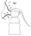
- the illustrated breast pump comprises a body member indicated generally at 2 preferably moulded from a thermoplastic elastomer such as polypropylene or polycarbonate, and including a generally conical breast engaging portion or horn 4 shaped to receive part of the breast of a user with the nipple located substantially centrally of the horn 4.
- a body member indicated generally at 2 preferably moulded from a thermoplastic elastomer such as polypropylene or polycarbonate, and including a generally conical breast engaging portion or horn 4 shaped to receive part of the breast of a user with the nipple located substantially centrally of the horn 4.
- the horn 4 feeds into a tubular portion 6 of the body member 2, the tubular portion 6 itself feeding into a main volume 8 of the body member 2.
- the body member 2 includes an upwardly open top end onto which may be attached an optional retaining annular collar 10. Secured between the collar 10 and the top end of the body member 2 is the annular flange of one end of a hollow, concertina-shaped sleeve 12 of an elastic material such a polyurethane which extends into the body member 2, the other end of the sleeve 12 within the body member 2 being closed.
- the arrangement is such that the co-operation between the collar 10 and the one end of the sleeve 12 seals the top end of the body member, the sleeve 12 thereby constituting a dividing barrier between the sealed interior of the body member and the external atmosphere, with the hollow interior of the sleeve 12 communicating with the atmosphere outside the body member 2.
- the sealing connection between the open end of the body member 2 and the flange on the sleeve 12 may be effected by the elasticity of the flange wrapping over the rim of the body member without a collar 10.
- An operating lever arm is indicated generally at 14 and is pivotally mounted to the body member at 16, the lever arm 14 including a first end extent 18 for engagement by the user to actuate the pump as will be detailed below, and a second end extent 20 for operative connection to the sleeve 12.
- the other end of the sleeve 12 has mounted externally or internally thereon a rigid end plate 22 to the centre of which one end of a link pin 24 is pivotally mounted.
- the pin 24 extends axially of the sleeve 12 and through the collar 10 with the other end of the pin 24 being attached to the second end extent 20 of the lever arm 14.
- the sleeve 12 is of an flexible material, for example silicone or a thermoplastic elastomer such as polyurethane, and has an inherent memory whereby the sleeve 12 tends to return towards the extended condition shown in Fig. 1 .
- the sleeve 12 extends to the rest condition of Fig. 1 , the balance of the lever arm 14 being such as to encourage the sleeve 12 and the arm 14 to return to their rest conditions as shown in Fig. 1 .
- the lower end of the body member 2 comprises an outlet 26 to which is mounted a duck bill type one way valve 28.
- the pump may optionally include an adaptor 30 by which the body member 2 is attached to a container 32, conveniently by a screw thread.
- the described breast pump operates as follows.
- the user takes hold of the container 2 and applies the horn 4 of the pump to her breast with sufficient pressure to seal against the breast. She then pivots the lever arm 14 about the pivot point 16 whereby, as detailed above, the concertina sleeve 12 is compacted.
- the volume 8 between the outside of the sleeve 12 and the inside of the surrounding body member 2 is increased.
- the one-way valve 28 and the co-operation between the collar 10 and the one end of the sleeve 12 the pressure in the volume 8 is reduced to create a vacuum whereby milk is expressed from the breast and into the volume 8.
- the sleeve 12 On release of the lever arm 14, the sleeve 12 returns to its extended condition in view of its inherent elasticity and the supplementary effect of the lever arm 14 to increase the pressure within the volume 8, that is releasing the suction therein allowing the valve to open and milk to flow and pump the milk through the valve 28 into the container 32 as a result of the vacuum release, this flow of milk from the body member 2 to the container 32 being supplemented by gravity.
- This procedure can be repeated until sufficient milk has been expressed or until all available milk has been expressed.
- the provision of the concertina sleeve 12 as the pumping element substantially eliminates the requirement for accurate machining, in that there is no need for the sleeve 12 to be guided during its compaction and extension movements. Furthermore, and as detailed above, there is substantial relative movement available between the lever arm 14 and the sleeve 12, in particular in view of the relatively flexible mounting of the link pin 24 to the second end extent 20 of the lever arm 14. Additional flexibility may be achieved by providing a link pin 24 of a non-rigid, bendable material. Conveniently the end plate 22, the link pin 24, the sleeve 12 and the lever arm 14 are manufactured as an integral unit.
- the central axis of the sleeve 12 may be other than substantially vertical, for example substantially horizontal
- the actuating means may be other than a lever arm 14 and may be movable other than towards the container 32, for example away from the container and by the thumb of the user
- the valve means may be other than a duck bill one way valve.
- the sleeve may be of a suitable elastic material such as a thermoplastic elastomer, for example polyurethane, or of silicone or of natural rubber
- the body member 2 and horn 4 may be of a suitable thermoplastic material such as polypropylene or polycarbonate.
- the container 32 is conveniently of a translucent or transparent plastic material.
- Actuating means may be electric or mechanical, hand-held or attached such as battery powered or a separate remote mains powered unit.
- FIG. 4 there is shown an alternative embodiment of the invention the operation of which is substantially the same as that of the embodiment of Figs 1 to 3 and which will therefore not be described in detail again.
- a sleeve 12' a free end of which is mounted to the body 2' and the other closed end of which extends transversely of the body 2' to seal the interior of the body 2' from the atmosphere.
- the sleeve 12' is of a substantially non-stretch material, comprising a non-stretching flexible material or a layer of elastic material, for example silicone or a thermoplastic elastomer such as polyurethane, to which is bonded, inlaid or insert moulded a substantially non-stretch layer such as a fabric mesh.
- a substantially non-stretch material comprising a non-stretching flexible material or a layer of elastic material, for example silicone or a thermoplastic elastomer such as polyurethane, to which is bonded, inlaid or insert moulded a substantially non-stretch layer such as a fabric mesh.
- One end of a lever 14' is secured centrally to the closed end of the sleeve 12' externally of the body 2', the other end of the lever 14' comprising an element 40 adapted to receive the thumb of a user, which element 40 may be ring-shaped as shown or of other suitable configuration.
- Displacement of the sleeve 12' from the rest condition shown in Fig. 4 to a displaced condition to create the required volume of reduced pressure within the body 2' is achieved by engaging the thumb of the user in the portion 40 and moving the thumb away from the pump in the direction of arrow T. This arrangement obviates the cost and energy loss associated with a hinged lever mechanism.
- the non-stretch nature of the material of the sleeve 12' ensures an energy-efficient arrangement.
- Figs. 1 to 3 which includes a concertina-shaped sleeve, shows a lever arm as the actuating means, it will be appreciated that other actuating means, such as a thumb-receiving element similar to that shown in Fig. 4 , could be used.
- Fig. 4 which includes a 'roll diaphragm' type sleeve, shows a thumb-receiving element as the actuating means, it will be appreciated that other actuating means, such as a lever arm similar to that shown in Figs. 1 to 3 , could be used.
- breast pumps which may be operated manually or electrically, which are substantially more energy efficient than heretofore, this efficiency being achieved either by the configuration or the material of the sleeve, or by both - i.e. the material of the sleeve 12 may be non-stretch - and which can be manufactured more economically and with less precision than heretofore.
- the horn of a breast pump is shaped to engage a region of the mother's breast whereby a sealed chamber is created in the pump and whereby a vacuum can be created in the chamber to express milk from the breast.
- Such inserts include a series of resilient, circumferentially spaced petals surrounding the nipple and arranged to apply a peristaltic pressure thereto by being moved in and out in accordance with the negative pressure created by the pump.
- the breast pump has a horn shaped to engage a region of a user's breast, the horn being of a relatively rigid material such as polypropylene or polycarbonate and having bonded thereto at least one region of relatively soft, elastic material such as a thermoplastic elastomer, the relatively soft material of the or each region infilling an associated aperture through the relatively rigid material to comprise the thickness of the horn at said region.
- a relatively rigid material such as polypropylene or polycarbonate
- relatively soft, elastic material such as a thermoplastic elastomer
- the soft material is an integral part of the horn, being bonded to the rigid material, and provides one or more regions of elasticity to the horn whereby the user can manipulate said region(s) which in turn stimulates the underlying area(s) of the breast, conveniently the nipple or an adjacent area, the rigid material providing the necessary support to the breast.
- the whole of the internal area of the rigid material is lined with said soft material, while the outer peripheral edge of the horn may comprise a lip of said soft material encasing the periphery of the rigid material.
- the horn comprises a two-shot moulding with the relatively soft, elastic material permanently bonded to the relatively rigid material by virtue of the inherent characteristics of the materials.
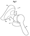
- a horn indicated generally at 4 which comprises a rigid shell 50 typically of polypropylene or polycarbonate in the lower regions of which, adjacent the tubular portion 6, is formed an aperture.
- the rigid shell 50 is lined with a layer 52 of a soft flexible elastic material such as a thermoplastic elastomer which is bonded to the shell 50 and which infills, at 54, the aperture in the shell 50 to comprise the full thickness of the horn at that region.
- the layer 52 includes a peripheral lip 56 which surrounds the outer peripheral edge of the shell 50.
- Integrally formed on the inner surface of the soft layer 52 in the region of the infill 54 and in the region above this infill may be a plurality of dimples 58 or similar small embossed areas.
- the described horn is manufactured by a two-shot moulding process, the first shot forming the rigid shell 50 and the second shot moulding on the soft layer 52 whereby the two layers are permanently bonded together.
- the soft layer 54 together with the lip 56 ensures a comfortable fit on the breast, while the presence of the soft infill at 54 enables the mother to manipulate her breast using her thumb 60 together with her finger 62.
- the strategically positioned dimples further assist in this stimulation.
- Figs 6 to 8 shows a preferred horn in which there are two opposed apertures in the rigid shell 50, the second aperture being immediately above the first, this second aperture also being infilled at 64 with the soft material to provide opposed regions of soft material which can be manipulated by the user's thumb 60 and finger 62 to stimulate lactation.
- a one-piece horn eliminates the requirement for assembly and disassembly, facilitates cleaning and is safer to use.
- the presence of the rigid shell 50 supports the breast of the user, while the presence of the infill(s) 54,64 enables manual stimulation of the breast to supplement the effect of the associated pump.
Landscapes
- Health & Medical Sciences (AREA)
- Heart & Thoracic Surgery (AREA)
- Biomedical Technology (AREA)
- Vascular Medicine (AREA)
- Engineering & Computer Science (AREA)
- Anesthesiology (AREA)
- Hematology (AREA)
- Life Sciences & Earth Sciences (AREA)
- Animal Behavior & Ethology (AREA)
- General Health & Medical Sciences (AREA)
- Public Health (AREA)
- Veterinary Medicine (AREA)
- Pediatric Medicine (AREA)
- External Artificial Organs (AREA)
- Eye Examination Apparatus (AREA)
Claims (21)
- Tire-lait comprenant un élément de corps (2) incluant une portion de mise en prise avec le sein (4) configurée pour venir en prise avec une région du sein d'une utilisatrice, un contenant (32) fixé à l'élément de corps (2) et un moyen de vanne (28) entre l'élément de corps (2) et le contenant (32), dans l'élément de corps (2), un manchon flexible (12, 12') rendant étanche l'intérieur de l'élément de corps (2) relativement à l'atmosphère, le manchon (12, 12') étant sélectivement déplaçable d'un état de repos à un état déplacé par un moyen d'actionnement (14, 14') fonctionnellement relié au manchon, un mouvement du manchon (12, 12') de l'état de repos à l'état déplacé créant un volume en augmentation de pression réduite dans l'élément de corps (2) moyennant quoi tout d'abord, le moyen de vanne (28) est fermé pour empêcher l'évacuation du contenant (32), et moyennant quoi le lait est expulsé par l'utilisatrice dans l'élément de corps (2), et un mouvement de retour du manchon (12, 12') de l'état déplacé à l'état étendu libérant la pression réduite en permettant au moyen de vanne (28) d'ouvrir le lait expulsé s'écoulant à travers le moyen de vanne (28) et dans le contenant, caractérisé en ce que la configuration du manchon (12, 12') ou du matériau du manchon (12, 12') est telle qu'elle prévient sensiblement un étirage du manchon (12, 12') lors d'un mouvement entre les états de repos et déplacé.
- Tire-lait selon la revendication 1, dans lequel le manchon est généralement en forme d'accordéon et est sélectivement déplaçable entre un état de repos étendu et un état déplacé compacté.
- Tire-lait selon la revendication 2, dans lequel la forme en accordéon possède une base fermée (22) à celle-ci dont au moins une partie est sensiblement rigide, un mouvement du manchon se faisant par la traction de la base depuis l'intérieur du manchon de manière à contracter sa longueur.
- Tire-lait selon l'une quelconque des revendications 2 à 3, dans lequel la forme en accordéon est en un matériau élastique dont les propriétés inhérentes sont telles que lors de la libération du moyen d'actionnement par l'utilisatrice, le manchon revient à son état étendu dans l'élément de corps.
- Tire-lait selon la revendication 1, dans lequel le manchon comprend un matériau sensiblement non étirable.
- Tire-lait selon la revendication 5, dans lequel le manchon comprend une couche flexible à laquelle est liée ou dans laquelle est placée une couche sensiblement non étirable.
- Tire-lait selon l'une quelconque des revendications 1 à 6, dans lequel le moyen d'actionnement comprend un bras de levier (14) monté d'une manière pivotante à sa région intermédiaire sur l'élément de corps (2), une étendue d'extrémité du bras de levier étant destinée pour la mise en prise avec l'utilisatrice, et l'autre étendue d'extrémité étant fonctionnellement reliée au manchon (12, 12').
- Tire-lait selon l'une quelconque des revendications 1 à 7, dans lequel une extrémité du manchon (12, 12') est fixée entre un collier (10) et une paroi de définition de l'élément de corps (2) moyennant quoi l'intérieur du manchon (12, 12') est rendu étanche relativement à l'intérieur de l'élément de corps (2), l'autre extrémité du manchon étant fermée.
- Tire-lait selon la revendication 8, dans lequel l'autre extrémité fermée du manchon supporte une plaque d'extrémité (22), un axe de liaison (24) s'étendant axialement dans le manchon et à travers le collier (10) pour interconnecter la plaque d'extrémité (12) et l'autre étendue d'extrémité du bras de levier moyennant quoi, lors d'un mouvement de pivotement du bras de levier par l'utilisatrice, l'axe de liaison (24) est déplacé sensiblement axialement du manchon pour compacter le manchon.
- Tire-lait selon la revendication 9, dans lequel la plaque d'extrémité (22), l'axe de liaison (24), le manchon (12, 12') et le bras de levier (14) comprennent une unité intégrale.
- Tire-lait selon la revendication 10, et incorporant des joints flexibles à une ou aux deux extrémités de l'axe de liaison.
- Tire-lait selon l'une quelconque des revendications 1 à 6, dans lequel le moyen d'actionnement comprend un élément fonctionnel dont une extrémité est fixée à une extrémité fermée du manchon, et dont l'autre extrémité supporte un élément de réception de pouce (40) pour recevoir le pouce d'une utilisatrice.
- Tire-lait selon la revendication 12, dans lequel un élément de poignée est réalisé comme un repos et une prise pour les doigts de la main d'actionnement, ladite poignée étant fixée rigidement au corps de pompe, l'agencement étant tel que, lors de la pose du pouce dans l'élément de réception de pouce, et lors de la traction du pouce vers les doigts, la base du manchon est tirée dans la direction généralement au loin du sein.
- Tire-lait selon l'une quelconque des revendications 1 à 13, dans lequel le moyen de vanne entre l'élément de corps et le contenant comprend une vanne à une voie du type en bec de canard.
- Tire-lait selon l'une quelconque des revendications précédentes, dans lequel la portion de mise en prise avec le sein comprend un cornet (4) configuré pour la mise en prise avec une région du sein d'une utilisatrice, et étant en un matériau rigide et auquel est liée au moins une région de matériau élastique mou, le matériau mou de la ou chaque région remplissant une ouverture associée (54) à travers le matériau rigide pour comprendre l'épaisseur du cornet à ladite région.
- Tire-lait selon la revendication 15, dans lequel le matériau rigide est le polypropylène ou le polycarbonate, et le matériau élastique mou est un élastomère thermoplastique.
- Tire-lait selon la revendication 15 ou la revendication 16, dans lequel il y a deux régions opposées de matériau élastique mou espacées de l'extrémité ouverte du cornet, une pour la localisation au-dessus du sein et une pour la localisation en dessous du sein d'une manière adjacente au téton pour la manipulation par le pouce et un doigt de l'utilisatrice.
- Tire-lait selon l'une quelconque des revendications 15 à 17, dans lequel l'ensemble de la zone interne du matériau rigide est revêtu avec ledit matériau mou.
- Tire-lait selon la revendication 18, où le bord périphérique extérieur du cornet comprend une lèvre (56) en matériau mou précité renfermant la périphérie du matériau rigide.
- Tire-lait selon l'une quelconque des revendications 15 à 19 et comprenant un moulage à deux charges d'injection avec le matériau élastique mou lié en permanence au matériau rigide en raison des caractéristiques inhérentes des matériaux.
- Tire-lait selon l'une quelconque des revendications précédentes, où le tire-lait est un tire-lait actionnable manuellement.
Applications Claiming Priority (3)
| Application Number | Priority Date | Filing Date | Title |
|---|---|---|---|
| GB0214525 | 2002-06-24 | ||
| GBGB0214525.8A GB0214525D0 (en) | 2002-06-24 | 2002-06-24 | Breast pump |
| PCT/GB2003/002633 WO2004000390A1 (fr) | 2002-06-24 | 2003-06-19 | Tire-lait |
Publications (2)
| Publication Number | Publication Date |
|---|---|
| EP1515760A1 EP1515760A1 (fr) | 2005-03-23 |
| EP1515760B1 true EP1515760B1 (fr) | 2012-03-28 |
Family
ID=9939161
Family Applications (1)
| Application Number | Title | Priority Date | Filing Date |
|---|---|---|---|
| EP03730376A Expired - Lifetime EP1515760B1 (fr) | 2002-06-24 | 2003-06-19 | Tire-lait |
Country Status (8)
| Country | Link |
|---|---|
| US (1) | US7413557B2 (fr) |
| EP (1) | EP1515760B1 (fr) |
| AT (1) | ATE551082T1 (fr) |
| AU (1) | AU2003241056B2 (fr) |
| CA (1) | CA2490361C (fr) |
| ES (1) | ES2384321T3 (fr) |
| GB (2) | GB0214525D0 (fr) |
| WO (1) | WO2004000390A1 (fr) |
Cited By (2)
| Publication number | Priority date | Publication date | Assignee | Title |
|---|---|---|---|---|
| DE202012008803U1 (de) | 2012-09-14 | 2013-12-16 | Mapa Gmbh | Manuelle Muttermilchpumpe |
| DE102014103567B4 (de) * | 2014-03-14 | 2025-07-10 | MAM Baby AG | Milchentnahmemodul für die manuelle Laktation von Milch aus der weiblichen Brust |
Families Citing this family (54)
| Publication number | Priority date | Publication date | Assignee | Title |
|---|---|---|---|---|
| US6749582B2 (en) | 2002-04-30 | 2004-06-15 | The First Years Inc. | Pumping breast milk |
| US7727182B2 (en) | 2002-08-23 | 2010-06-01 | Medela Holding Ag | Manual breastpump with stimulation feature |
| USD636072S1 (en) | 2003-04-28 | 2011-04-12 | Medela Holding Ag | Manual breastpump |
| US7776008B2 (en) * | 2003-08-08 | 2010-08-17 | Playtex Products, Inc. | Manual breast pump |
| JP4969034B2 (ja) * | 2004-10-06 | 2012-07-04 | ピジョン株式会社 | 搾乳器 |
| US8118772B2 (en) * | 2004-10-13 | 2012-02-21 | Stella Dao | Breast pump device with self-contained breast milk reservoir |
| US7559915B2 (en) * | 2004-10-13 | 2009-07-14 | Stella Dao | Breast pump device with self-contained breast milk reservoir |
| WO2007017968A1 (fr) | 2005-08-09 | 2007-02-15 | Pigeon Corporation | Dispositif de traite |
| AT503143B1 (de) | 2006-01-24 | 2008-04-15 | Mam Babyartikel | Milchpumpe sowie aufsatzteil hiefür |
| AT9121U1 (de) * | 2006-01-24 | 2007-05-15 | Mam Babyartikel | Aufsatzteil für eine milchpumpe |
| WO2007120622A2 (fr) * | 2006-04-11 | 2007-10-25 | Playtex Products, Inc | Tire-lait manuel |
| US8187227B2 (en) * | 2006-11-01 | 2012-05-29 | Medela Holding Ag | Self returning contamination barrier |
| JP5079364B2 (ja) | 2007-03-27 | 2012-11-21 | ピジョン株式会社 | 搾乳器 |
| JP4505756B2 (ja) * | 2007-04-02 | 2010-07-21 | ジェクス株式会社 | 搾乳器 |
| ITPR20070089A1 (it) * | 2007-11-14 | 2009-05-15 | Medel S P A | Apparato per estrarre latte da una mammella e relativo gruppo pompa. |
| EP2138197B1 (fr) * | 2008-06-26 | 2010-12-22 | Trimed AG | Pompe à lait |
| CN102271726B (zh) * | 2008-11-07 | 2014-10-08 | 辛普里斯公司 | 吸奶器 |
| US8398584B2 (en) | 2009-01-16 | 2013-03-19 | Learning Curve Brands, Inc. | Breast pump and method of use |
| KR200456766Y1 (ko) | 2009-04-14 | 2011-11-17 | 김수용 | 자동 모유 착유기 |
| US8444596B2 (en) * | 2009-06-22 | 2013-05-21 | Lansinoh Laboratories, Inc. | Breast milk collection apparatus and components thereof |
| US8167833B2 (en) * | 2009-07-01 | 2012-05-01 | Pigeon Corporation | Breast pump |
| EP2324868A1 (fr) * | 2009-07-28 | 2011-05-25 | Koninklijke Philips Electronics N.V. | Transmission flexible pour tire-lait |
| US8469770B2 (en) | 2009-10-20 | 2013-06-25 | Dawn Michele Alva | Multifunction brassiere cup |
| US9011372B2 (en) | 2010-07-22 | 2015-04-21 | Platinum Products Holding, Inc. | Manual breast pump with resilient return |
| EP2441480A1 (fr) * | 2010-10-15 | 2012-04-18 | Koninklijke Philips Electronics N.V. | Entonnoir pour tire-lait |
| CN102068721A (zh) * | 2011-01-08 | 2011-05-25 | 蒋一新 | 手动按摩吸奶器 |
| CA2871641C (fr) * | 2012-04-30 | 2016-12-13 | Ossur Hf | Dispositif prothetique, systeme et procede pour accroitre une attache de mise au vide |
| CN102764457B (zh) * | 2012-08-13 | 2015-01-14 | 广州健士婴童用品有限公司 | 负压可调的吸奶器 |
| US9155339B2 (en) | 2013-02-04 | 2015-10-13 | Dawn Michele Alva | Garments for a nursing woman |
| US10426705B2 (en) | 2013-09-05 | 2019-10-01 | Lansinoh Laboratories, Inc. | Colostrum collection system |
| EP3164100B1 (fr) | 2014-07-01 | 2018-04-18 | Ossur Iceland EHF | Mécanisme de pompe pour système de suspension sous vide |
| KR101562533B1 (ko) * | 2014-12-11 | 2015-10-23 | 주식회사 한국지이 | 유축기 |
| AU2016221967B2 (en) * | 2015-02-20 | 2018-11-08 | Medela Holding Ag | Breast shield having a flexible edge |
| US10434230B2 (en) * | 2015-02-20 | 2019-10-08 | Medela Holding Ag | Adapter with media separating diaphragm for a breast shield |
| EP3058966A1 (fr) | 2015-02-20 | 2016-08-24 | Medela Holding AG | Tire-lait |
| SG11201806734VA (en) * | 2016-02-10 | 2018-09-27 | Exploramed Nc7 Inc | Breast pump container assemblies and methods |
| US10434231B2 (en) | 2016-04-29 | 2019-10-08 | Exploramed Nc7, Inc. | Apparatus and methods for biomimetic expression of breast milk |
| US10238153B2 (en) | 2016-06-29 | 2019-03-26 | Rumina Nursingwear | Garments for a nursing woman |
| WO2018039421A1 (fr) | 2016-08-26 | 2018-03-01 | Ossur Iceland Ehf | Système de pompe. |
| CA3035271C (fr) | 2016-09-20 | 2024-06-18 | Medela Holding Ag | Dispositif d'aspiration et d'amenee comprenant une unite d'entrainement et une piece de raccordement |
| US11241048B2 (en) | 2016-10-17 | 2022-02-08 | Rumina Nursingwear | Garments for nursing or for hands-free use of a breast pump |
| DE202018006777U1 (de) | 2017-06-15 | 2022-12-14 | Chiaro Technology Limited | Brustpumpensystem |
| CN108295325B (zh) * | 2018-02-12 | 2020-10-09 | 绍兴柯桥韩丝针纺有限公司 | 一种压力可调的吸奶器 |
| US10716882B2 (en) * | 2018-03-07 | 2020-07-21 | Ameda, Inc. | Apparatus and methods for universal breast pump kit |
| EP3539583A1 (fr) | 2018-03-12 | 2019-09-18 | Koninklijke Philips N.V. | Agencement de capuchon pour sein pour ensemble de tire-lait |
| US11260152B2 (en) * | 2018-05-17 | 2022-03-01 | Kindestcup.Com | Apparatus for collecting breast milk |
| CN112638438B (zh) | 2018-09-06 | 2024-08-06 | 兰思诺实验室有限公司 | 用于吸乳器的振动波形 |
| US11426499B2 (en) | 2018-09-06 | 2022-08-30 | Lansinoh Laboratories, Inc. | Breast pumps |
| WO2020051438A1 (fr) | 2018-09-06 | 2020-03-12 | Lansinoh Laboratories, Inc. | Tire-lait électrique à boucle fermée |
| GB202004395D0 (en) | 2020-03-26 | 2020-05-13 | Chiaro Technology Ltd | Lima |
| GB2622570B (en) | 2022-08-31 | 2024-12-11 | Chiaro Technology Ltd | Breast pump |
| GB2622196A (en) | 2022-08-31 | 2024-03-13 | Chiaro Technology Ltd | Measurement system |
| CN223170071U (zh) * | 2024-06-26 | 2025-08-01 | 深圳市路特佳成供应链管理有限公司 | 吸奶器和吸乳护罩 |
| WO2026082269A1 (fr) * | 2024-10-15 | 2026-04-23 | Medela Ag | Tire-lait et module de chambre de pompage d'un tel tire-lait |
Family Cites Families (23)
| Publication number | Priority date | Publication date | Assignee | Title |
|---|---|---|---|---|
| US3399695A (en) * | 1966-11-25 | 1968-09-03 | Theodore A. Stehlin | Valve including elastomeric boot with sealing ring |
| US3769982A (en) * | 1971-09-24 | 1973-11-06 | R Schulte | Physiological drainage system with closure means responsive to downstream suction |
| US4680028A (en) * | 1984-07-02 | 1987-07-14 | Lact-Assist, Incorporated | Flexible breast receptor for breast pump |
| GB8422861D0 (en) * | 1984-09-11 | 1984-10-17 | Avent Medical Ltd | Single handed breast pump |
| CH666614A5 (de) * | 1984-12-24 | 1988-08-15 | Isg Ag | Verfahren zum foerdern der wehentaetigkeit bei schwangeren frauen. |
| ATE74775T1 (de) * | 1985-04-16 | 1992-05-15 | Elena M Grant | Transportierbare elektrisch betriebene einrichtung zum absaugen von muttermilch. |
| DE3709560A1 (de) * | 1987-03-24 | 1988-10-13 | Nejdet Celik | Milchpumpe |
| CH676795A5 (fr) * | 1989-03-01 | 1991-03-15 | Ameda Ag | |
| US5049126A (en) * | 1990-02-16 | 1991-09-17 | Isg/Ag | Breast pump with nipple stimulating insert |
| EP0466462A1 (fr) | 1990-07-10 | 1992-01-15 | I S G Ag | Tire-lait à massage pour une lactation améliorée |
| US5415632A (en) * | 1994-01-10 | 1995-05-16 | Playskool, Inc. | Breast pump |
| GB2299027B (en) * | 1995-03-24 | 1999-02-17 | Cannon Rubber Ltd | Diaphragm breast pump |
| US5843029A (en) * | 1995-10-16 | 1998-12-01 | Gerber/Baby Care | Manual breast pump |
| US6110140A (en) * | 1996-09-17 | 2000-08-29 | Medela, Inc. | Manual breastmilk pump |
| US5971952A (en) * | 1996-12-30 | 1999-10-26 | Medo; Elena M. | Manual breast pump |
| EP1034807A1 (fr) * | 1998-03-06 | 2000-09-13 | Ameda AG | Cloche de suction pour pompe tire-lait |
| WO1999044650A1 (fr) * | 1998-03-06 | 1999-09-10 | Ameda Ag Medical Equipment | Pompe tire-lait |
| GB2340755B (en) * | 1998-08-24 | 2002-09-25 | Cannon Rubber Ltd | Breast pump insert |
| US6387072B1 (en) * | 1998-12-10 | 2002-05-14 | Medela Holding Ag | Breastpump with universal hood base and interchangeable suction hoods |
| US20010016708A1 (en) * | 1999-05-26 | 2001-08-23 | Kong Carl Cheung Tung | Fluid displacement pumps |
| US6383164B1 (en) * | 2000-09-26 | 2002-05-07 | Gerber Products Company | Massaging breast pump and funnel therefor |
| NO315309B1 (no) * | 2001-06-18 | 2003-08-18 | Mamma Lactans As | Brystkopp, samt fremgangsmate ved fremstilling av brystkopp, samt fremgangsmate ved pumping av brystmelk ved hjelp av brystkoppen |
| US6749582B2 (en) * | 2002-04-30 | 2004-06-15 | The First Years Inc. | Pumping breast milk |
-
2002
- 2002-06-24 GB GBGB0214525.8A patent/GB0214525D0/en not_active Ceased
-
2003
- 2003-06-19 EP EP03730376A patent/EP1515760B1/fr not_active Expired - Lifetime
- 2003-06-19 US US10/518,900 patent/US7413557B2/en not_active Expired - Fee Related
- 2003-06-19 ES ES03730376T patent/ES2384321T3/es not_active Expired - Lifetime
- 2003-06-19 WO PCT/GB2003/002633 patent/WO2004000390A1/fr not_active Ceased
- 2003-06-19 CA CA2490361A patent/CA2490361C/fr not_active Expired - Fee Related
- 2003-06-19 AU AU2003241056A patent/AU2003241056B2/en not_active Ceased
- 2003-06-19 GB GB0314349A patent/GB2391176B/en not_active Expired - Fee Related
- 2003-06-19 AT AT03730376T patent/ATE551082T1/de active
Cited By (3)
| Publication number | Priority date | Publication date | Assignee | Title |
|---|---|---|---|---|
| DE202012008803U1 (de) | 2012-09-14 | 2013-12-16 | Mapa Gmbh | Manuelle Muttermilchpumpe |
| EP2708248A1 (fr) | 2012-09-14 | 2014-03-19 | MAPA GmbH | Pompe à lait maternel manuelle |
| DE102014103567B4 (de) * | 2014-03-14 | 2025-07-10 | MAM Baby AG | Milchentnahmemodul für die manuelle Laktation von Milch aus der weiblichen Brust |
Also Published As
| Publication number | Publication date |
|---|---|
| CA2490361A1 (fr) | 2003-12-31 |
| ATE551082T1 (de) | 2012-04-15 |
| AU2003241056A1 (en) | 2004-01-06 |
| US7413557B2 (en) | 2008-08-19 |
| AU2003241056B2 (en) | 2007-06-07 |
| WO2004000390A1 (fr) | 2003-12-31 |
| CA2490361C (fr) | 2012-03-20 |
| US20060111664A1 (en) | 2006-05-25 |
| EP1515760A1 (fr) | 2005-03-23 |
| GB0214525D0 (en) | 2002-08-07 |
| GB2391176B (en) | 2005-12-07 |
| ES2384321T3 (es) | 2012-07-03 |
| GB2391176A (en) | 2004-02-04 |
| GB0314349D0 (en) | 2003-07-23 |
Similar Documents
| Publication | Publication Date | Title |
|---|---|---|
| EP1515760B1 (fr) | Tire-lait | |
| US10493188B2 (en) | Highly efficient breastpump and system for expressing breastmilk | |
| US7776008B2 (en) | Manual breast pump | |
| US9486564B2 (en) | Breast shield for a breast pump | |
| TWI583408B (zh) | 乳罩單元 | |
| EP1735031B1 (fr) | Entonnoir supple pour tire-lait | |
| JP7280667B2 (ja) | 搾乳器 | |
| US20050154348A1 (en) | Breast pump | |
| US20090062731A1 (en) | Breast Pump | |
| AU2007214354B2 (en) | Breast pump | |
| EP4385536A1 (fr) | Ensemble de protection mammaire, agencement de réglage et procédé | |
| RU2806993C2 (ru) | Упругая прокладка, выполненная с возможностью крепления к элементу воздушного канала молокоотсоса | |
| CN222238439U (zh) | 用于向乳房施加真空的可穿戴系统和可穿戴的手动吸乳器 | |
| US20260048183A1 (en) | Manual breast pump kit | |
| EP4633691A1 (fr) | Ensemble téterelle, agencement de réglage et méthode | |
| WO2026087318A2 (fr) | Tire-lait | |
| HK1099239B (en) | Soft breastshield |
Legal Events
| Date | Code | Title | Description |
|---|---|---|---|
| PUAI | Public reference made under article 153(3) epc to a published international application that has entered the european phase |
Free format text: ORIGINAL CODE: 0009012 |
|
| 17P | Request for examination filed |
Effective date: 20050117 |
|
| AK | Designated contracting states |
Kind code of ref document: A1 Designated state(s): AT BE BG CH CY CZ DE DK EE ES FI FR GB GR HU IE IT LI LU MC NL PT RO SE SI SK TR |
|
| AX | Request for extension of the european patent |
Extension state: AL LT LV MK |
|
| DAX | Request for extension of the european patent (deleted) | ||
| RAP1 | Party data changed (applicant data changed or rights of an application transferred) |
Owner name: JACKEL INTERNATIONAL LIMITED Owner name: SAMSON, ILAN |
|
| 17Q | First examination report despatched |
Effective date: 20070322 |
|
| RAP1 | Party data changed (applicant data changed or rights of an application transferred) |
Owner name: SAMSON, ILAN |
|
| RIN1 | Information on inventor provided before grant (corrected) |
Inventor name: WEBB, IAN Inventor name: SAMSON, ILAN |
|
| GRAP | Despatch of communication of intention to grant a patent |
Free format text: ORIGINAL CODE: EPIDOSNIGR1 |
|
| GRAS | Grant fee paid |
Free format text: ORIGINAL CODE: EPIDOSNIGR3 |
|
| GRAA | (expected) grant |
Free format text: ORIGINAL CODE: 0009210 |
|
| AK | Designated contracting states |
Kind code of ref document: B1 Designated state(s): AT BE BG CH CY CZ DE DK EE ES FI FR GB GR HU IE IT LI LU MC NL PT RO SE SI SK TR |
|
| REG | Reference to a national code |
Ref country code: GB Ref legal event code: FG4D |
|
| REG | Reference to a national code |
Ref country code: CH Ref legal event code: EP |
|
| REG | Reference to a national code |
Ref country code: AT Ref legal event code: REF Ref document number: 551082 Country of ref document: AT Kind code of ref document: T Effective date: 20120415 |
|
| REG | Reference to a national code |
Ref country code: IE Ref legal event code: FG4D |
|
| REG | Reference to a national code |
Ref country code: DE Ref legal event code: R096 Ref document number: 60340414 Country of ref document: DE Effective date: 20120524 |
|
| REG | Reference to a national code |
Ref country code: NL Ref legal event code: T3 |
|
| REG | Reference to a national code |
Ref country code: CH Ref legal event code: NV Representative=s name: MEYER & KOLLEGEN |
|
| REG | Reference to a national code |
Ref country code: ES Ref legal event code: FG2A Ref document number: 2384321 Country of ref document: ES Kind code of ref document: T3 Effective date: 20120703 |
|
| PG25 | Lapsed in a contracting state [announced via postgrant information from national office to epo] |
Ref country code: GR Free format text: LAPSE BECAUSE OF FAILURE TO SUBMIT A TRANSLATION OF THE DESCRIPTION OR TO PAY THE FEE WITHIN THE PRESCRIBED TIME-LIMIT Effective date: 20120629 Ref country code: FI Free format text: LAPSE BECAUSE OF FAILURE TO SUBMIT A TRANSLATION OF THE DESCRIPTION OR TO PAY THE FEE WITHIN THE PRESCRIBED TIME-LIMIT Effective date: 20120328 |
|
| REG | Reference to a national code |
Ref country code: AT Ref legal event code: MK05 Ref document number: 551082 Country of ref document: AT Kind code of ref document: T Effective date: 20120328 |
|
| PG25 | Lapsed in a contracting state [announced via postgrant information from national office to epo] |
Ref country code: CY Free format text: LAPSE BECAUSE OF FAILURE TO SUBMIT A TRANSLATION OF THE DESCRIPTION OR TO PAY THE FEE WITHIN THE PRESCRIBED TIME-LIMIT Effective date: 20120328 |
|
| PG25 | Lapsed in a contracting state [announced via postgrant information from national office to epo] |
Ref country code: SI Free format text: LAPSE BECAUSE OF FAILURE TO SUBMIT A TRANSLATION OF THE DESCRIPTION OR TO PAY THE FEE WITHIN THE PRESCRIBED TIME-LIMIT Effective date: 20120328 Ref country code: SE Free format text: LAPSE BECAUSE OF FAILURE TO SUBMIT A TRANSLATION OF THE DESCRIPTION OR TO PAY THE FEE WITHIN THE PRESCRIBED TIME-LIMIT Effective date: 20120328 Ref country code: EE Free format text: LAPSE BECAUSE OF FAILURE TO SUBMIT A TRANSLATION OF THE DESCRIPTION OR TO PAY THE FEE WITHIN THE PRESCRIBED TIME-LIMIT Effective date: 20120328 Ref country code: RO Free format text: LAPSE BECAUSE OF FAILURE TO SUBMIT A TRANSLATION OF THE DESCRIPTION OR TO PAY THE FEE WITHIN THE PRESCRIBED TIME-LIMIT Effective date: 20120328 Ref country code: CZ Free format text: LAPSE BECAUSE OF FAILURE TO SUBMIT A TRANSLATION OF THE DESCRIPTION OR TO PAY THE FEE WITHIN THE PRESCRIBED TIME-LIMIT Effective date: 20120328 |
|
| PG25 | Lapsed in a contracting state [announced via postgrant information from national office to epo] |
Ref country code: SK Free format text: LAPSE BECAUSE OF FAILURE TO SUBMIT A TRANSLATION OF THE DESCRIPTION OR TO PAY THE FEE WITHIN THE PRESCRIBED TIME-LIMIT Effective date: 20120328 Ref country code: PT Free format text: LAPSE BECAUSE OF FAILURE TO SUBMIT A TRANSLATION OF THE DESCRIPTION OR TO PAY THE FEE WITHIN THE PRESCRIBED TIME-LIMIT Effective date: 20120730 |
|
| PG25 | Lapsed in a contracting state [announced via postgrant information from national office to epo] |
Ref country code: MC Free format text: LAPSE BECAUSE OF NON-PAYMENT OF DUE FEES Effective date: 20120630 Ref country code: DK Free format text: LAPSE BECAUSE OF FAILURE TO SUBMIT A TRANSLATION OF THE DESCRIPTION OR TO PAY THE FEE WITHIN THE PRESCRIBED TIME-LIMIT Effective date: 20120328 Ref country code: AT Free format text: LAPSE BECAUSE OF FAILURE TO SUBMIT A TRANSLATION OF THE DESCRIPTION OR TO PAY THE FEE WITHIN THE PRESCRIBED TIME-LIMIT Effective date: 20120328 |
|
| PLBE | No opposition filed within time limit |
Free format text: ORIGINAL CODE: 0009261 |
|
| STAA | Information on the status of an ep patent application or granted ep patent |
Free format text: STATUS: NO OPPOSITION FILED WITHIN TIME LIMIT |
|
| 26N | No opposition filed |
Effective date: 20130103 |
|
| REG | Reference to a national code |
Ref country code: DE Ref legal event code: R097 Ref document number: 60340414 Country of ref document: DE Effective date: 20130103 |
|
| PG25 | Lapsed in a contracting state [announced via postgrant information from national office to epo] |
Ref country code: BG Free format text: LAPSE BECAUSE OF FAILURE TO SUBMIT A TRANSLATION OF THE DESCRIPTION OR TO PAY THE FEE WITHIN THE PRESCRIBED TIME-LIMIT Effective date: 20120628 |
|
| PG25 | Lapsed in a contracting state [announced via postgrant information from national office to epo] |
Ref country code: TR Free format text: LAPSE BECAUSE OF FAILURE TO SUBMIT A TRANSLATION OF THE DESCRIPTION OR TO PAY THE FEE WITHIN THE PRESCRIBED TIME-LIMIT Effective date: 20120328 |
|
| PG25 | Lapsed in a contracting state [announced via postgrant information from national office to epo] |
Ref country code: LU Free format text: LAPSE BECAUSE OF NON-PAYMENT OF DUE FEES Effective date: 20120619 |
|
| PG25 | Lapsed in a contracting state [announced via postgrant information from national office to epo] |
Ref country code: HU Free format text: LAPSE BECAUSE OF FAILURE TO SUBMIT A TRANSLATION OF THE DESCRIPTION OR TO PAY THE FEE WITHIN THE PRESCRIBED TIME-LIMIT Effective date: 20030619 |
|
| REG | Reference to a national code |
Ref country code: FR Ref legal event code: PLFP Year of fee payment: 14 |
|
| REG | Reference to a national code |
Ref country code: FR Ref legal event code: PLFP Year of fee payment: 15 |
|
| REG | Reference to a national code |
Ref country code: FR Ref legal event code: PLFP Year of fee payment: 16 |
|
| PGFP | Annual fee paid to national office [announced via postgrant information from national office to epo] |
Ref country code: IT Payment date: 20190624 Year of fee payment: 17 Ref country code: IE Payment date: 20190624 Year of fee payment: 17 Ref country code: NL Payment date: 20190617 Year of fee payment: 17 |
|
| PGFP | Annual fee paid to national office [announced via postgrant information from national office to epo] |
Ref country code: BE Payment date: 20190618 Year of fee payment: 17 Ref country code: FR Payment date: 20190617 Year of fee payment: 17 |
|
| PGFP | Annual fee paid to national office [announced via postgrant information from national office to epo] |
Ref country code: CH Payment date: 20190625 Year of fee payment: 17 |
|
| PGFP | Annual fee paid to national office [announced via postgrant information from national office to epo] |
Ref country code: GB Payment date: 20190521 Year of fee payment: 17 Ref country code: ES Payment date: 20190715 Year of fee payment: 17 Ref country code: DE Payment date: 20190625 Year of fee payment: 17 |
|
| REG | Reference to a national code |
Ref country code: DE Ref legal event code: R119 Ref document number: 60340414 Country of ref document: DE |
|
| REG | Reference to a national code |
Ref country code: CH Ref legal event code: PL |
|
| REG | Reference to a national code |
Ref country code: NL Ref legal event code: MM Effective date: 20200701 |
|
| GBPC | Gb: european patent ceased through non-payment of renewal fee |
Effective date: 20200619 |
|
| REG | Reference to a national code |
Ref country code: BE Ref legal event code: MM Effective date: 20200630 |
|
| PG25 | Lapsed in a contracting state [announced via postgrant information from national office to epo] |
Ref country code: FR Free format text: LAPSE BECAUSE OF NON-PAYMENT OF DUE FEES Effective date: 20200630 Ref country code: GB Free format text: LAPSE BECAUSE OF NON-PAYMENT OF DUE FEES Effective date: 20200619 Ref country code: NL Free format text: LAPSE BECAUSE OF NON-PAYMENT OF DUE FEES Effective date: 20200701 Ref country code: CH Free format text: LAPSE BECAUSE OF NON-PAYMENT OF DUE FEES Effective date: 20200630 Ref country code: IE Free format text: LAPSE BECAUSE OF NON-PAYMENT OF DUE FEES Effective date: 20200619 Ref country code: LI Free format text: LAPSE BECAUSE OF NON-PAYMENT OF DUE FEES Effective date: 20200630 |
|
| PG25 | Lapsed in a contracting state [announced via postgrant information from national office to epo] |
Ref country code: DE Free format text: LAPSE BECAUSE OF NON-PAYMENT OF DUE FEES Effective date: 20210101 Ref country code: BE Free format text: LAPSE BECAUSE OF NON-PAYMENT OF DUE FEES Effective date: 20200630 |
|
| PG25 | Lapsed in a contracting state [announced via postgrant information from national office to epo] |
Ref country code: IT Free format text: LAPSE BECAUSE OF NON-PAYMENT OF DUE FEES Effective date: 20200619 |
|
| REG | Reference to a national code |
Ref country code: ES Ref legal event code: FD2A Effective date: 20211102 |
|
| PG25 | Lapsed in a contracting state [announced via postgrant information from national office to epo] |
Ref country code: ES Free format text: LAPSE BECAUSE OF NON-PAYMENT OF DUE FEES Effective date: 20200620 |