EP1515820B1 - Scie a mouvement alternatif, pilotee a la main et munie d'un systeme de guidage de lame de scie - Google Patents
Scie a mouvement alternatif, pilotee a la main et munie d'un systeme de guidage de lame de scie Download PDFInfo
- Publication number
- EP1515820B1 EP1515820B1 EP03759862A EP03759862A EP1515820B1 EP 1515820 B1 EP1515820 B1 EP 1515820B1 EP 03759862 A EP03759862 A EP 03759862A EP 03759862 A EP03759862 A EP 03759862A EP 1515820 B1 EP1515820 B1 EP 1515820B1
- Authority
- EP
- European Patent Office
- Prior art keywords
- guide
- saw blade
- hand
- sliding block
- sliding blocks
- Prior art date
- Legal status (The legal status is an assumption and is not a legal conclusion. Google has not performed a legal analysis and makes no representation as to the accuracy of the status listed.)
- Expired - Lifetime
Links
Images


Classifications
-
- B—PERFORMING OPERATIONS; TRANSPORTING
- B23—MACHINE TOOLS; METAL-WORKING NOT OTHERWISE PROVIDED FOR
- B23D—PLANING; SLOTTING; SHEARING; BROACHING; SAWING; FILING; SCRAPING; LIKE OPERATIONS FOR WORKING METAL BY REMOVING MATERIAL, NOT OTHERWISE PROVIDED FOR
- B23D51/00—Sawing machines or sawing devices working with straight blades, characterised only by constructional features of particular parts; Carrying or attaching means for tools, covered by this subclass, which are connected to a carrier at both ends
- B23D51/02—Sawing machines or sawing devices working with straight blades, characterised only by constructional features of particular parts; Carrying or attaching means for tools, covered by this subclass, which are connected to a carrier at both ends of beds; of guiding arrangements for work-tables or saw carriers; of frames
- B23D51/025—Sawing machines or sawing devices working with straight blades, characterised only by constructional features of particular parts; Carrying or attaching means for tools, covered by this subclass, which are connected to a carrier at both ends of beds; of guiding arrangements for work-tables or saw carriers; of frames of arrangements for guiding the saw blade
- B23D51/026—Sawing machines or sawing devices working with straight blades, characterised only by constructional features of particular parts; Carrying or attaching means for tools, covered by this subclass, which are connected to a carrier at both ends of beds; of guiding arrangements for work-tables or saw carriers; of frames of arrangements for guiding the saw blade by plural opposed guide surfaces
Definitions
- the present invention is based on a hand-held saw according to the preamble of claim 1.
- WO 02/22297 is a hand-saw with saw blade guide system known that leads between two side jaws, the flat sides of the saw blade.
- the control of the jaws is proposed by means of servomotor.
- the present invention according to claim 1 has the advantage that the guide system is optionally switched on or off.
- the automatically adjusting to the position of the saw blade clamping means have the advantage that both flat sides of the saw blade are performed with matching minimum support force and undesirable high frictional forces between the guide means and the saw blade are avoided.
- the guide means are arranged elastically so that they seek to put into the saw blade supported activated position, in the deactivated position optionally a sudden activation of the guide means is possible as soon as the working conditions so require.
- a pushbutton is arranged at the actuation of the clamping means go into their activated, the saw blade supporting position, the activation of the guide means is particularly comfortable possible.
- an actuating means for deactivating the guide means is arranged on the saw blade tensioning mechanism, the guide means are automatically deactivated when the saw blade is changed or when it is released.
- slotted guide slots of the sliding blocks are arranged at an angle to the vertical relative to the slide pin of the jaws in the self-locking area, in particular 5 to 6 degrees inclination to the vertical, are Clamping jaws can be closed with high holding force, so that the collet can not be opened by forces from outside or when the saw blade is in contact with high force.
- the housing carries a finger guard, the risk of injury when handling the lifting saw is significantly reduced, with the U-shaped configuration of the finger guard, the saw blade is easily recognizable and controlled feasible.
- FIG. 1 shows a schematically illustrated, hand-held jigsaw 10 obliquely from above, which receives in a housing 12 an electric motor, not shown, with a gear for reciprocating drive a lifting rod 16.
- a lifting rod 16 At the lifting rod 16 is a saw blade 18 with its clamping end, but coupled captive, which in viewing direction down a base plate 14 of the jigsaw 10 passes.
- the saw blade 18 At its saw blade back 23, which faces the toothed side 17, the saw blade 18 is supported on a support roller 22, which in the feed direction 19 reciprocating pendulum the blade 18, if necessary switchable can give a pendulum motion.
- guide tongs 26 configured guide means which can support the saw blade 18 on its flat sides opposite.
- a distance between guide jaws 24, 25 of the guide tongs 26 is adjustable to the respective saw blade thickness of the clamped saw blade 18.
- the guide jaws 24, 25 are pivotable about a pivot point 30 (FIG. 3) between the position and the position open. In the closed position, the outermost ends of the guide jaws 24, 25 are supported laterally on the flat sides of the saw blade.
- the lower end of the lifting rod 16 is provided with a clamping device 20 in which the clamping end of the saw blade 18 is captively clamped and releasably by pressing a clamping lever 21.
- the guide tongs 26 is switched to the open position, this position is optionally closed by pressing a side button 52 in the position displaceable, in which the guide jaws 24, 25 are supported laterally on the saw blade 18.
- Figure 2 shows another embodiment of a jigsaw 100, which in principle coincides with that of Figure 1, the guide tongs 260, however, extends laterally of the support roller 220 and is bent in the viewing direction to the right, so that it extends behind the lifting rod 160 into the interior of the housing 120 , In the direction of view in front of the lifting rod 160 extends parallel to this from top to bottom attached to the housing 120, a U-shaped protective bracket 27, which serves as finger protection against accidental contact of the saw blade 180 and protects the operator of the jigsaw 100 from injury.
- the housing 120 is pivotally coupled to a base plate 120 and the saw blade 180 is laterally supported by guide jaws 240, 250.
- a clamping lever 210 is arranged, which is pivotable in the viewing direction to the left to release the saw blade 180-across the front of the housing 120.
- a pushbutton 520 is arranged, upon actuation thereof the guide tongs 260 abruptly closes to laterally support the saw blade 180.
- a pivot lever 15 is provided for adjusting the pendulum stroke of the pendulum roller 220.
- FIG. 3 shows the assembly of the guide tongs 260 in their position relative to the lifting rod 160 and the pendulum roller 220.
- the guide jaws 240, 250 extend horizontally from the toothed side 170 of the saw blade 180 towards the pendulum roller 220 and again vertically bent upward at the pivot point 30 are fixed to the housing.
- the guide jaws 240, 250 each carry a extending from the viewing plane forwardly extending cam bolts 35, 36, each a sliding guide slot 38, 39 of two sliding blocks 45, 46 passes, which are guided up or down to the left.
- the slide guide slots 38, 39 extend at approximately 5 degrees inclined to the vertical or to the axis of the lifting rod 160, so that when viewed in the upward direction sliding blocks 45, 46, the guide pins 35, 36 are displaced outwards and in this displacement, the guide jaws 240, 250th swing outward to open. If the sliding blocks 45, 46 are pushed downwards, the slide guide slots 38, 39 engage the guide bolts 35, 36 so that the guide pliers 260 close and support the lower ends of the guide shoes 240, 250 laterally on the saw blade 180.
- the sliding blocks 45, 46 are resiliently biased by compression springs 42, 43 ( Figure 5, 6) and seek the sliding blocks 45, 46 to push axially upwards.
- the push button 520 carries in the axial extension of a slider 54 which extends on a cam 56 in the upper region of the sliding block 45 to the push button 520 down.
- the push button 520 is shifted in the viewing direction to the left, wherein it is supported against a compression spring 53 and has shifted its slider 54 relative to the cam 56 in the release position.
- the sliding block 45 can be abruptly moved in its upwardly directed position, wherein he releases the pressed in his downward position with his driving pin 48 down second slide 46.
- a ramp 50 carrying arm is rotated approximately centrally about the axis of the lifting rod 160, wherein the driving pin 48 and the two sliding blocks 45, 46 are pressed down.
- the slider 54 comes in a locking position relative to the cam 56 as soon as it is moved together with the sliding block 45 down.
- cam 56 releases the slider 54 again, so that the push button 520 biased by the compression spring 53 is again open in its position displaced, in which the cam 56 is locked by the slider 54 in the vertical direction of movement is.
- Figure 4 shows a cross section of the jigsaw machine 100 in the region of the guide tongs 260 seen from behind, wherein the pivot point 30 of the guide jaws 240, 250 is particularly clearly visible and is formed by a screw bolt.
- the sliding blocks 45, 46 partially covered by the guide jaws 240, 250 are vertically displaced upward in position, so that the guide tongs 240 are closed in position.
- the ramp 50 has released the driving pin 48 and with this in the viewing direction left sliding block 45, which follows the shorter sliding block 46.
- the driving pin 48 is captively pressed in a bore, not shown, transversely to its direction of displacement, wherein it dives with its free end in a groove-like, unspecified depression in the upper end of the shorter sliding block 46 in part.
- the push button 520 remains in its inwardly depressed position as long as the slider 45 is seated in its vertical uppermost position.
- the guide bolts 35, 36, the rear view of the guide jaws 240, 250 is visible, pivoted toward each other, so that the guide tongs 260 is closed in position.
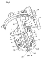
- Figure 5 shows the guide tongs 260 closed in their position in which the sliding blocks 45, 46 are displaced upwards and the cam 56 locks the slider 54, so that the pushbutton 520 remains pressed axially inwards.
- the ramp 50 slides in a wedge-like manner on the driving pin 48, so that, as described above, the sliding blocks 45, 46 moved in the direction of observation down and the collet is opened.
- FIG. 6 shows the guide tongs 260 according to FIG. 5 open in the position because the sliding blocks 45, 46 are displaced vertically downwards against the compression springs 42, 43 and thereby the guide pins 35, 36 and thus the guide jaws 240, 250 spread apart.
- the cam 56 has slid past in the viewing direction on the right of the slider 54 and has released this against the biasing force of the compression spring 53, so that the push button 520 could move in the direction of viewing to the right in the open position.
- the slider 54 is positioned above the cam 56 and blocks this and the sliding block 45 in the direction of movement upwards.
- the sliding block 45 Since the sliding block 45 is supported with its driving pin 48 on top of the adjacent sliding block 46, this sliding block 46 must follow the movement of the driving pin 48 downward, acted upon by the ramp 50.
- the driving pin 48 relative to the sliding block 46 has a vertical distance of about 0.5 mm, so that the driving pin 48 must first be pressed down by this amount before the sliding block 46 is acted upon and can follow the movement , As a result, in the closed position, it is possible to adjust freely within a specific tolerance range to central deposits of the saw blade 180.
- the left in the direction of observation guide shoe 240 must go through a longer travel, it realized that the left sliding block 46 can move to the driving pin 48 by the amount of about 0.5 mm beyond its zero position path and thus quite safely come to rest on the side surface of the saw blade 180. This ensures a secure, uniform guidance of the saw blade 180 within the foreseeable tolerance range.
Landscapes
- Engineering & Computer Science (AREA)
- Mechanical Engineering (AREA)
- Sawing (AREA)
Claims (9)
- Scie sauteuse portative (10, 100) comprenant un boîtier (12, 120) et une lame de scie (18, 180) pouvant être entraînée en va-et-vient et pouvant être amenée dans une position de serrage amovible, ainsi que des moyens de guidage en forme de pince (26, 260) qui guident la lame de scie (18, 180) en s'appuyant latéralement contre celle-ci,
caractérisée en ce que
les moyens de guidage (26, 260) peuvent être commutés simplement à la main, au choix dans une position latéralement écartée de la lame de scie (18, 180) et/ou dans une position latéralement appuyée contre la lame de scie (18, 180), sachant que les moyens de guidage (26, 260) adoptent la position latéralement écartée de la lame de scie (18, 180) dès que la lame de scie (18, 180) adopte sa position de serrage, sachant que les moyens de guidage (26, 260), dans la position écartée, cherchent à parvenir, avec une précontrainte élastique, dans la position appuyée contre la lame de scie (18, 180), alors que par l'actionnement d'un bouton-poussoir (52, 520) disposé au niveau de la scie à métaux manuelle (10, 100), en particulier par un actionnement brusque, ils viennent de leur position latéralement écartée de la lame de scie (18, 180) dans leur position appuyée contre la lame de scie (18, 180). - Scie sauteuse portative selon la revendication 1,
caractérisée en ce qu'
on prévoit un autre bouton de commande (21, 210) dont l'actionnement permet d'amener les moyens de guidage (26, 260) de leur position latéralement appuyée contre la lame de scie (18, 180) dans leur position latéralement écartée de la lame de scie (18, 180). - Scie sauteuse portative selon la revendication 1 ou 2,
caractérisée en ce qu'
on prévoit des coulisseaux (45, 46) guidés linéairement, précontraints élastiquement, pour fermer ou ouvrir les moyens de guidage en forme de pince (26, 260). - Scie sauteuse portative selon l'une des revendications 1 à 3,
caractérisée en ce que
deux coulisseaux (45, 46) sont logés de façon mobile l'un par rapport à l'autre, sachant que le premier coulisseau (45) entraîne obligatoirement l'autre (46) dans une direction de mouvement et peut être ramené dans la direction de mouvement opposée indépendamment du coulisseau entraîné. - Scie sauteuse portative selon la revendication précédente,
caractérisée en ce qu'
un moyen d'entraînement (48) est disposé entre le premier coulisseau (45) et le deuxième (46), avec en position « fermée » de la pince de guidage (26), une distance axiale d'environ 0,5 mm entre le moyen d'entraînement (48) et le deuxième coulisseau (46) dans la direction de déplacement vers la position « ouverte ». - Scie sauteuse portative selon la revendication 5,
caractérisée en ce que
le levier de serrage (21) servant de moyen d'actionnement (21) pour amener la pince de guidage (26) dans la position « ouverte » pour desserrer ou serrer la lame de scie (18, 180), est pourvu de moyens de calage, en particulier d'une rampe (50), permettant de déplacer vers le bas la tige d'entraînement (48) conjointement avec les coulisseaux (45). - Scie sauteuse portative selon l'une des revendications précédentes,
caractérisée en ce que
les coulisseaux (45, 46) comportant des fentes de coulissement (38, 39) accrochent des boulons de coulissement (35, 36) des mâchoires de guidage (24, 25) de la pince de guidage (26) de telle sorte que lors de leur mouvement vers le bas, ils ouvrent la pince de guidage (26) et lors de leur mouvement dirigé vers le haut, ils ferment la pince de guidage (26). - Scie sauteuse portative selon l'une des revendications précédentes,
caractérisée en ce que
les fentes de coulissement (38, 39) s'étendent en formant un certain angle par rapport aux boulons de coulissement (35, 36), de sorte que seuls les coulisseaux (45, 46) lors de leur déplacement, peuvent déplacer les boulons de coulissement (35, 36), mais que les boulons de coulissement (35, 36) ne peuvent pas déplacer les coulisseaux (45, 46). - Scie sauteuse portative (10) selon l'une des revendications précédentes,
caractérisée en ce que
du côté frontal de la lame de scie (18), parallèlement à celle-ci, une protection pour les doigts (27) s'étend vers la plaque de base (14) en étant fixée de manière imperdable au boîtier (12).
Applications Claiming Priority (5)
| Application Number | Priority Date | Filing Date | Title |
|---|---|---|---|
| DE10227058 | 2002-06-17 | ||
| DE10227058 | 2002-06-17 | ||
| DE10308828A DE10308828A1 (de) | 2002-06-17 | 2003-02-27 | Hand-Hubsägemaschine mit Sägeblattführungssystem |
| DE10308828 | 2003-02-27 | ||
| PCT/DE2003/002021 WO2003106087A1 (fr) | 2002-06-17 | 2003-06-17 | Scie a mouvement alternatif, pilotee a la main et munie d'un systeme de guidage de lame de scie |
Publications (2)
| Publication Number | Publication Date |
|---|---|
| EP1515820A1 EP1515820A1 (fr) | 2005-03-23 |
| EP1515820B1 true EP1515820B1 (fr) | 2008-01-02 |
Family
ID=29737608
Family Applications (1)
| Application Number | Title | Priority Date | Filing Date |
|---|---|---|---|
| EP03759862A Expired - Lifetime EP1515820B1 (fr) | 2002-06-17 | 2003-06-17 | Scie a mouvement alternatif, pilotee a la main et munie d'un systeme de guidage de lame de scie |
Country Status (6)
| Country | Link |
|---|---|
| US (1) | US7111405B2 (fr) |
| EP (1) | EP1515820B1 (fr) |
| JP (1) | JP4499556B2 (fr) |
| CN (1) | CN100382921C (fr) |
| DE (1) | DE50308924D1 (fr) |
| WO (1) | WO2003106087A1 (fr) |
Families Citing this family (18)
| Publication number | Priority date | Publication date | Assignee | Title |
|---|---|---|---|---|
| GB0405729D0 (en) * | 2004-03-15 | 2004-04-21 | Gmca Pty Ltd | Power tool bearing arrangement |
| DE102004045623B4 (de) * | 2004-09-21 | 2015-01-15 | Robert Bosch Gmbh | Handhubsägemaschine |
| DE102004045624A1 (de) * | 2004-09-21 | 2006-04-06 | Robert Bosch Gmbh | Hubsägemaschine |
| DE102006025768A1 (de) * | 2006-05-31 | 2007-12-13 | Robert Bosch Gmbh | Hubsäge mit einer Befestigungseinrichtung für ein Sägeblatt |
| DE102006030558A1 (de) * | 2006-07-03 | 2008-01-10 | Robert Bosch Gmbh | Handhubsägemaschine |
| DE102007006482B3 (de) * | 2007-02-09 | 2008-06-12 | Festool Gmbh | Hubsäge, insbesondere Stichsäge |
| DE102007030246A1 (de) * | 2007-06-29 | 2009-01-08 | Robert Bosch Gmbh | Handwerkzeugmaschine |
| US8813372B2 (en) | 2007-09-14 | 2014-08-26 | Milwaukee Electric Tool Corporation | Blade clamp mechanism |
| US9981327B2 (en) | 2007-09-21 | 2018-05-29 | Black & Decker Inc. | Cutting angle indicator in jigsaw housing with dust extraction |
| US9827623B2 (en) | 2007-09-21 | 2017-11-28 | Black & Decker Inc. | Control of reciprocation speed and orbital magnitude of a jigsaw with a plurality of material and/or task descriptive icons |
| US8033026B2 (en) | 2007-09-21 | 2011-10-11 | Black & Decker Inc. | Adjustable and removable keel assembly and blade guide for a jigsaw |
| US10029322B2 (en) | 2007-09-21 | 2018-07-24 | Black & Decker Inc. | Housing of a cutting tool including blade storage, integral blade guard and motor ventilation pathway |
| US8230607B2 (en) | 2008-05-09 | 2012-07-31 | Milwaukee Electric Tool Corporation | Keyless blade clamp for a power tool |
| DE102008002066A1 (de) | 2008-05-29 | 2009-12-03 | Robert Bosch Gmbh | Werkzeugmaschine, insbesondere handgeführte Werkzeugmaschine |
| US20100178856A1 (en) * | 2009-01-09 | 2010-07-15 | Omar Jesus Cruz | Cordless power gasket scraper and surface cleaning tool with light source |
| CN102126232B (zh) * | 2010-01-20 | 2014-01-15 | 苏州宝时得电动工具有限公司 | 曲线锯 |
| US8578615B2 (en) | 2011-09-12 | 2013-11-12 | Black & Decker Inc. | Jigsaw with deployable keel and tiltable shoe |
| US9559628B2 (en) | 2013-10-25 | 2017-01-31 | Black & Decker Inc. | Handheld power tool with compact AC switch |
Family Cites Families (9)
| Publication number | Priority date | Publication date | Assignee | Title |
|---|---|---|---|---|
| US4308852A (en) * | 1979-06-23 | 1982-01-05 | Siegfried Gebhart | Apparatus for sawing different materials |
| DE3613279A1 (de) * | 1986-04-19 | 1987-10-22 | Festo Kg | Stichsaege |
| DE19513076A1 (de) * | 1995-04-07 | 1996-10-10 | Scintilla Ag | Stichsäge |
| US6568089B1 (en) * | 1999-06-04 | 2003-05-27 | Porter-Cable/Delta | Reciprocating saw having compact configuration and independent stability |
| DE29910173U1 (de) * | 1999-06-11 | 1999-09-02 | FESTO Tooltechnic GmbH & Co., 73728 Esslingen | Stichsäge |
| CN2434113Y (zh) * | 2000-07-28 | 2001-06-13 | 北京紫玉电子产品厂 | 带锯锯条导向装置 |
| DE10045890A1 (de) | 2000-09-16 | 2002-04-04 | Bosch Gmbh Robert | Säge mit einem Werkzeugführungsmechanismus |
| DE10119561A1 (de) * | 2001-04-21 | 2002-10-24 | Hilti Ag | Stichsäge mit Führungsmittel |
| DE10153355B4 (de) * | 2001-10-29 | 2011-05-12 | Hilti Aktiengesellschaft | Handgeführte Stichsäge mit einer Führungsvorrichtung |
-
2003
- 2003-06-17 EP EP03759862A patent/EP1515820B1/fr not_active Expired - Lifetime
- 2003-06-17 WO PCT/DE2003/002021 patent/WO2003106087A1/fr not_active Ceased
- 2003-06-17 DE DE50308924T patent/DE50308924D1/de not_active Expired - Lifetime
- 2003-06-17 US US10/496,160 patent/US7111405B2/en not_active Expired - Lifetime
- 2003-06-17 JP JP2004512962A patent/JP4499556B2/ja not_active Expired - Fee Related
- 2003-06-17 CN CNB038015528A patent/CN100382921C/zh not_active Expired - Fee Related
Also Published As
| Publication number | Publication date |
|---|---|
| JP2005529756A (ja) | 2005-10-06 |
| CN100382921C (zh) | 2008-04-23 |
| EP1515820A1 (fr) | 2005-03-23 |
| JP4499556B2 (ja) | 2010-07-07 |
| DE50308924D1 (de) | 2008-02-14 |
| CN1592665A (zh) | 2005-03-09 |
| WO2003106087A1 (fr) | 2003-12-24 |
| US20050000098A1 (en) | 2005-01-06 |
| US7111405B2 (en) | 2006-09-26 |
Similar Documents
| Publication | Publication Date | Title |
|---|---|---|
| EP1515820B1 (fr) | Scie a mouvement alternatif, pilotee a la main et munie d'un systeme de guidage de lame de scie | |
| DE2649765C2 (fr) | ||
| CH654779A5 (de) | Pneumatisch angetriebene spannvorrichtung. | |
| DE202010013185U1 (de) | Kraftwerkzeug | |
| DE102004045623B4 (de) | Handhubsägemaschine | |
| DE3141248C2 (de) | Einrichtung zum Zuführen von Schrauben für einen motorbetriebenen Schraubenzieher | |
| DE102010038675A1 (de) | Befestigungsvorrichtung | |
| CH673975A5 (fr) | ||
| EP1799386B1 (fr) | Patin pour scie a mouvement alternatif manuelle | |
| DE10308828A1 (de) | Hand-Hubsägemaschine mit Sägeblattführungssystem | |
| DE2403830B1 (de) | Vorspannvorrichtung für eine Spannzwinge | |
| DE2543067C3 (de) | Verfahren und Vorrichtung zum Verschweißen von sich überlappenden Teilen eines Bandes aus thermoplastischem Material | |
| DE4310268C1 (de) | Schutzhaubenträger, insbesondere für eine Tischkreissäge | |
| EP0578072B1 (fr) | Dispositif pour fixer une plaque de support d'un attelage de remorque | |
| DE19857669C2 (de) | Mechanische Anordnung zur Begrenzung der Bewegung von Arbeitsbühnen | |
| DE202008002933U1 (de) | Holzspalter | |
| DE3334763A1 (de) | Feststellvorrichtung an automatischen saegemaschinen zum blockieren und festklemmen der zu zertrennenden stangen, z.b. aus metall | |
| EP0287958B1 (fr) | Dispositif de serrage d'une lame de scie dans une machine de dressage de lames de scie | |
| DE102019110984A1 (de) | Klemmhalter | |
| DE102010020655A1 (de) | Wasserpumpenzange | |
| DE10052610A1 (de) | Vorrichtung zur Einstellung der Schnitttiefe eines handgeführten Elektrowerkzeugs, Schutzhaube für ein handgeführtes Elektrowerkzeug sowie handgeführtes Elektrowerkzeug | |
| DE4344129A1 (de) | Kraftgetriebene Schwertsäge | |
| DE69031228T2 (de) | Fräsenführer | |
| DE2715565A1 (de) | Spannvorrichtung | |
| DE814898C (de) | Zungenamboss fuer eine Drahtheftmaschine |
Legal Events
| Date | Code | Title | Description |
|---|---|---|---|
| PUAI | Public reference made under article 153(3) epc to a published international application that has entered the european phase |
Free format text: ORIGINAL CODE: 0009012 |
|
| 17P | Request for examination filed |
Effective date: 20050117 |
|
| AK | Designated contracting states |
Kind code of ref document: A1 Designated state(s): AT BE BG CH CY CZ DE DK EE ES FI FR GB GR HU IE IT LI LU MC NL PT RO SE SI SK TR |
|
| RBV | Designated contracting states (corrected) |
Designated state(s): DE FR GB IT |
|
| 17Q | First examination report despatched |
Effective date: 20051117 |
|
| GRAP | Despatch of communication of intention to grant a patent |
Free format text: ORIGINAL CODE: EPIDOSNIGR1 |
|
| GRAS | Grant fee paid |
Free format text: ORIGINAL CODE: EPIDOSNIGR3 |
|
| GRAA | (expected) grant |
Free format text: ORIGINAL CODE: 0009210 |
|
| AK | Designated contracting states |
Kind code of ref document: B1 Designated state(s): DE FR GB IT |
|
| REG | Reference to a national code |
Ref country code: GB Ref legal event code: FG4D Free format text: NOT ENGLISH |
|
| REF | Corresponds to: |
Ref document number: 50308924 Country of ref document: DE Date of ref document: 20080214 Kind code of ref document: P |
|
| GBT | Gb: translation of ep patent filed (gb section 77(6)(a)/1977) |
Effective date: 20080411 |
|
| ET | Fr: translation filed | ||
| PLBE | No opposition filed within time limit |
Free format text: ORIGINAL CODE: 0009261 |
|
| STAA | Information on the status of an ep patent application or granted ep patent |
Free format text: STATUS: NO OPPOSITION FILED WITHIN TIME LIMIT |
|
| 26N | No opposition filed |
Effective date: 20081003 |
|
| PGFP | Annual fee paid to national office [announced via postgrant information from national office to epo] |
Ref country code: GB Payment date: 20150623 Year of fee payment: 13 |
|
| PGFP | Annual fee paid to national office [announced via postgrant information from national office to epo] |
Ref country code: IT Payment date: 20150625 Year of fee payment: 13 |
|
| REG | Reference to a national code |
Ref country code: FR Ref legal event code: PLFP Year of fee payment: 14 |
|
| PGFP | Annual fee paid to national office [announced via postgrant information from national office to epo] |
Ref country code: FR Payment date: 20160621 Year of fee payment: 14 |
|
| GBPC | Gb: european patent ceased through non-payment of renewal fee |
Effective date: 20160617 |
|
| PG25 | Lapsed in a contracting state [announced via postgrant information from national office to epo] |
Ref country code: GB Free format text: LAPSE BECAUSE OF NON-PAYMENT OF DUE FEES Effective date: 20160617 |
|
| PG25 | Lapsed in a contracting state [announced via postgrant information from national office to epo] |
Ref country code: IT Free format text: LAPSE BECAUSE OF NON-PAYMENT OF DUE FEES Effective date: 20160617 |
|
| REG | Reference to a national code |
Ref country code: FR Ref legal event code: ST Effective date: 20180228 |
|
| PG25 | Lapsed in a contracting state [announced via postgrant information from national office to epo] |
Ref country code: FR Free format text: LAPSE BECAUSE OF NON-PAYMENT OF DUE FEES Effective date: 20170630 |
|
| PGFP | Annual fee paid to national office [announced via postgrant information from national office to epo] |
Ref country code: DE Payment date: 20190822 Year of fee payment: 17 |
|
| REG | Reference to a national code |
Ref country code: DE Ref legal event code: R119 Ref document number: 50308924 Country of ref document: DE |
|
| PG25 | Lapsed in a contracting state [announced via postgrant information from national office to epo] |
Ref country code: DE Free format text: LAPSE BECAUSE OF NON-PAYMENT OF DUE FEES Effective date: 20210101 |