EP1516579A1 - Appareil et procedé pour mesurer des composants sanguins - Google Patents
Appareil et procedé pour mesurer des composants sanguins Download PDFInfo
- Publication number
- EP1516579A1 EP1516579A1 EP20040255553 EP04255553A EP1516579A1 EP 1516579 A1 EP1516579 A1 EP 1516579A1 EP 20040255553 EP20040255553 EP 20040255553 EP 04255553 A EP04255553 A EP 04255553A EP 1516579 A1 EP1516579 A1 EP 1516579A1
- Authority
- EP
- European Patent Office
- Prior art keywords
- tissue
- examined
- blood component
- component measuring
- photo
- Prior art date
- Legal status (The legal status is an assumption and is not a legal conclusion. Google has not performed a legal analysis and makes no representation as to the accuracy of the status listed.)
- Granted
Links
Images

Classifications
-
- A—HUMAN NECESSITIES
- A61—MEDICAL OR VETERINARY SCIENCE; HYGIENE
- A61B—DIAGNOSIS; SURGERY; IDENTIFICATION
- A61B5/00—Measuring for diagnostic purposes; Identification of persons
- A61B5/14—Devices for taking samples of blood ; Measuring characteristics of blood in vivo, e.g. gas concentration within the blood, pH-value of blood
-
- A—HUMAN NECESSITIES
- A61—MEDICAL OR VETERINARY SCIENCE; HYGIENE
- A61B—DIAGNOSIS; SURGERY; IDENTIFICATION
- A61B5/00—Measuring for diagnostic purposes; Identification of persons
- A61B5/145—Measuring characteristics of blood in vivo, e.g. gas concentration or pH-value ; Measuring characteristics of body fluids or tissues, e.g. interstitial fluid or cerebral tissue
- A61B5/1455—Measuring characteristics of blood in vivo, e.g. gas concentration or pH-value ; Measuring characteristics of body fluids or tissues, e.g. interstitial fluid or cerebral tissue using optical sensors, e.g. spectral photometrical oximeters
-
- A—HUMAN NECESSITIES
- A61—MEDICAL OR VETERINARY SCIENCE; HYGIENE
- A61B—DIAGNOSIS; SURGERY; IDENTIFICATION
- A61B5/00—Measuring for diagnostic purposes; Identification of persons
- A61B5/145—Measuring characteristics of blood in vivo, e.g. gas concentration or pH-value ; Measuring characteristics of body fluids or tissues, e.g. interstitial fluid or cerebral tissue
- A61B5/14532—Measuring characteristics of blood in vivo, e.g. gas concentration or pH-value ; Measuring characteristics of body fluids or tissues, e.g. interstitial fluid or cerebral tissue for measuring glucose, e.g. by tissue impedance measurement
-
- A—HUMAN NECESSITIES
- A61—MEDICAL OR VETERINARY SCIENCE; HYGIENE
- A61B—DIAGNOSIS; SURGERY; IDENTIFICATION
- A61B5/00—Measuring for diagnostic purposes; Identification of persons
- A61B5/68—Arrangements of detecting, measuring or recording means, e.g. sensors, in relation to patient
- A61B5/6801—Arrangements of detecting, measuring or recording means, e.g. sensors, in relation to patient specially adapted to be attached to or worn on the body surface
- A61B5/6813—Specially adapted to be attached to a specific body part
- A61B5/6825—Hand
- A61B5/6826—Finger
-
- A—HUMAN NECESSITIES
- A61—MEDICAL OR VETERINARY SCIENCE; HYGIENE
- A61B—DIAGNOSIS; SURGERY; IDENTIFICATION
- A61B5/00—Measuring for diagnostic purposes; Identification of persons
- A61B5/68—Arrangements of detecting, measuring or recording means, e.g. sensors, in relation to patient
- A61B5/6801—Arrangements of detecting, measuring or recording means, e.g. sensors, in relation to patient specially adapted to be attached to or worn on the body surface
- A61B5/683—Means for maintaining contact with the body
- A61B5/6838—Clamps or clips
Definitions
- the present invention relates to an apparatus and method for measuring bio-tissue components, and more particularly, to an apparatus and method for measuring blood components such as blood sugar.
- a human body consists of 73% water and 27% other components. 1/3 of the water is extracellular, while 2/3 is intracellular. Among the extracellular water, 3/4 is interstitial fluid, while 1/4 is intravascular fluid.
- the blood sugar refers to the concentration of glucose in blood. The concentration of glucose contained in the blood flowing along a capillary vessel is similar to that of the interstitial fluid.
- the human body tissue consists of flexible cells between which the interstitial fluid exists. Therefore, when external pressure is applied to the tissue, the tissue is depressed and the interstitial fluid travels.
- the measured result may vary in accordance with a variety of conditions such as a surface state of a measured tissue, pressure applied to the tissue, and the like. Therefore, in order to predict the concentration of a specific component in the tissue, there is a need for an active control of the measured tissue. In addition, it is methodologically important how to control the tissue measured.
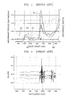
- FIGS. 1 and 2 show why such an active control and control method are important.
- FIG. 1 shows absorbance spectrums of blood components such as glucose, hemoglobin, albumin, triacetine, and gamma (y )-globulin and an absorbance spectrum of water.
- the absorbance spectrums G2, G3, G4, G5, and G6 of hemoglobin, glucose, albumin, triacetine, and gamma (y )-globulin are obtained by extracting the absorbance spectrum of the water from an absorbance spectrum (not shown) of aqueous solution of each component having a path length of 0.5 mm with respect to a near infrared ray.
- the left-longitudinal axis represents each absorbance of major blood components and the right-longitudinal axis represents an absorbance of the water.
- the absorbance of the water at each of the wave bands 1600 nm and 2200 nm is greater than those of other blood components by more than 20 times. It can be further noted that the near infrared ray absorption band of the glucose and the near infrared ray absorption bands of other blood components overlap one another.
- the inventor of the present invention measured an absorbance of an aqueous solution having a thickness of 0.5 mm and containing 500 mg of glucose using a conventional apparatus and method. Only the absorbance of the glucose can be obtained by extracting the absorbance of the water from the whole absorbance of the aqueous solution.
- the measured results are shown in Table 1.
- the measured results shown in Table 1 correspond to the absorbance of the glucose contained in a soft tissue having a thickness of 2 mm. Wavelength (nm) 1689 (peak) 2094 (peak) 2238 (valley) 2274 (peak) 2360 (peak) Absorbance 0.0006 0.0046 0.00209 0.00246 0.00507
- the inventor further measured the absorbance variation of a 1.7 mm thickness web tissue between the thumb and the index finger using the conventional apparatus and method.
- FIG. 2 shows the measured results.
- the absorbance variation when light having a wavelength of 1650 nm is used, the absorbance variation is about ⁇ 0.03 Abs. It can be further noted that, when light having a wavelength of 2200 nm is used, the absorbance variation is about ⁇ 0.05 Abs.
- the repeated measuring error ( ⁇ 0.03 Abs) is more than 100 times greater than the absorbance (0.0006 Abs) of the glucose. It can be further noted that, when the light having the wavelength of 2200 nm is used, the repeated measuring error (0.05 Abs) is 40 times greater than the absorbance (0.00209 Abs).
- the absorbance variation according to the repeated measurements becomes much greater than the actual absorbance of the tissue to be examined.
- the absorbance variation is increased, the reproducibility is deteriorated. That is, the absorbance of a tissue measured may vary whenever being measured. As a result, the absorbance measuring results are not reliable and the blood component data obtained through the absorbance analysis are indefensible.
- a blood component measuring apparatus comprising: a fixing apparatus for fixing an examinee's body part; a light source portion for irradiating light to a tissue to be examined of the examinee's body part in a state where the light source portion is covered by the tissue to be examined; a photo-detector for detecting light passing through the tissue to be examined, the photo-detector facing the light source portion; and an analyzer for analyzing the light detected by the photo-detector, wherein the fixing apparatus comprises a first fixing member for fixing a portion, which is connected to the tissue to be examined, of the examinee's body part; and a second fixing member for fixing the other part, which is connected to the tissue to be examined, of the examinee's body part, wherein the first and second fixing members are designed to move based on a region where the tissue to be examined is to be located.
- the present invention provides a blood component measuring apparatus that can measure blood components such as blood sugar without using blood and can minimize absorbance variation (i.e., the measurement error) that may be caused by variation of an interfacing between the measuring apparatus and the tissue to be examined.
- a blood component measuring apparatus that can measure blood components such as blood sugar without using blood and can minimize absorbance variation (i.e., the measurement error) that may be caused by variation of an interfacing between the measuring apparatus and the tissue to be examined.
- the first and second fixing members may be provided on the same base plate so that the first and second fixing members are pivotted on their axes fixed on the same base plate.
- the first fixing member may comprise a first support pivotable on a fixed portion; a movable member mounted on the first support and providing a space where the part connected to the tissue of the examinee's body part is located, a portion of the movable member being movable to vary the size of the space in response to a size of the part connected to the tissue of the examinee's body part; and an adjustor for adjusting movement of the movable member.
- the first fixing member may further comprise a catching means for pulling the part connected to the tissue of the examinee's body part downward or outward.
- the adjustor may comprise a first adjustor for increasing the space in a longitudinal direction of the first portion of the examinee's body part and a second adjustor for increasing the space in a perpendicular direction to the longitudinal direction of the part connected to the tissue of the examinee's body part.
- the blood component measuring apparatus may further comprise a stopper for stopping a pivotal motion of the first support.
- the second fixing member may comprise a second support pivotable on a fixed portion; a supporting member mounted on the second support to support the other part connected to the tissue of the examinee's body part, the supporting member being movable to meet a size of the other part of the examinee's body part; a catcher for pulling a portion of the tissue to be examined; a movable member for moving the catcher; and an adjustor for adjusting movement of the supporting member.
- the catcher may comprise an upper member and a lower member contacting.
- the blood component measuring apparatus may further comprise a stopper for stopping rotation of the second support.
- the light source portion may comprise: a light source for irradiating the light and a photo-guider for guiding the light irradiated from the light source portion to the tissue to be examined.
- the photo-guider may be provided with a heater for adjusting a temperature of the tissue to be examined.
- the heater is formed on a surface of the photo-guider or formed enclosing the photo-guider.
- the photo-detector may comprise: a photo-guide pillar contacting the tissue to be examined to guide the light passing through the tissue to be examined; and a protecting tube enclosing the photo-guide pillar and make an interfacing area between the photo-guide pillar and the tissue to be examined gentle.
- the protecting tube comprises: a portion in parallel with the photo-guide pillar and a portion bent from the parallel portion toward a lower end of the photo-guide pillar. The bent portion is inclined at an angle of 30-60°with respect to a horizontal plane which is perpendicular to the photo-guide pillar is disposed.
- a blood component measuring method using the above-described apparatus comprising: mounting the examinee's body part on the fixing apparatus such that the light source portion contact a first surface of the tissue to be examined of the examinee's body part; uniformly maintaining a temperature of the tissue to be examined of the examinee's body part at a predetermined temperature; applying a tension to the tissue to be examined; and obtaining desired data from the tissue to be examined.
- Another object of the present invention is to provide a blood component measuring method using the apparatus.
- the step of applying a tension may be performed before the step of uniformly maintaining a temperature.
- the temperature of the tissue to be examined may be maintained in a range of 36-40°C.
- the tension may be applied by spreading opposing portions of the examinee's body part.
- the tension may be further applied by pulling the tissue to be examined in a state where the opposing portions of the examinee's body part are spread.
- the tension may be further applied by pulling or pressing a first region adjacent to a target region of the tissue to be examined where the measurement is realized.
- the tension may be further applied by pulling or pressing a second region adjacent to a target region of the tissue to be examined where the measurement is realized.
- the blood component measuring method may further comprise fixing the examinee's body part itself.
- the obtaining desired data further comprises: contacting the photo-detector with a second surface of the tissue to be examined facing the light source portion; irradiating the light to one side of the tissue to be examined and detecting the light passing through the tissue to be examined; amplifying the detected light; and analysing the amplified light to output data on the blood component in the tissue to be examined.
- a contacting portion between a periphery of the photo-detector and the tissue to be examined is inclined at an angle of a range 30-60°.
- the first region is pressed by pressure equal to or less than 0.5 N/mm 2 .
- the absorbance variation i.e., the absorbance measuring error
- the absorbance measuring condition can be reduced.
- the reproducibility with respect to the absorbance measuring condition can be enhanced, thereby improving the reliability of blood components data obtained through the absorbance analysis.
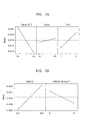
- FIGS. 3a and 3b show the test results.
- a left portion shows an absorbance variation of a tissue to be examined in response to temperature variation
- a middle portion shows an absorbance variation in accordance with the number of scans
- a right portion shows an absorbance variation according to thickness variation of the tissue to be examined.
- a left portion shows an absorbance variation in accordance with inclined angle variation of a periphery of a photo-detector for detecting light passing through the tissue to be examined
- a right portion shows an absorbance variation in response to variation of pressure applied to the tissue to be examined.
- the temperature of the tissue to be examined is the factor most affecting the absorbance variation, while the number of scans does not affect much the absorbance variation.
- the test results show that the temperature of the tissue to be examined becomes the most important factor for measuring the blood components. Accordingly, it is preferable to maintain the temperature of the tissue to be examined within a predetermined range. In order to enhance the reproducibility of the tissue to be examined, it is further preferable that the temperature of the tissue to be examined be maintained as high as possible.
- the tissue to be examined is a portion of a human body
- the temperature of the tissue to be examined it is preferable to maintain the temperature of the tissue to be examined to be less than, for example, 40 °C, more preferably, to be in a range of 36-40 °C.
- the absorbance is affected by an angle between peripheries of the photo-detector and the tissue to be examined.
- the absorbance variation caused by the angle can be attenuated by preventing a shape of the tissue to be examined from being steeply varied. This will be described more in detail later.
- the reproducibility of the measurement can be improved by thinning the tissue to be examined.
- an examinee feels a pain when a pressure applied to the tissue to be examined becomes greater than 0.5 N/mm 2 . Therefore, it is preferable that the pressure applied to the tissue to be examined be less than 0.5 N/mm 2 .
- the tissue to be examined uniform by uniformly spreading the tissue to be examined, it is also possible to improve the absorbance reproducibility. That is, to spread the tissue to be examined, it is preferable that relatively high pressure be applied to the tissue to be examined. However, it is preferable that the pressure be less than a predetermined value so that the examinee does not feel the pain.
- FIG. 4 shows a blood component measuring apparatus according to a preferred embodiment of the present invention.
- the present invention improves an interfacing between a part of human body and an apparatus.
- the interfacing will be hereinafter called "IHA.”
- the IHA can be improved by (a) maintaining a temperature of the tissue to be examined as high as possible during the measurement, (b) applying a pressure to maintain a thickness of the tissue to be examined as thin as possible, (c) forming the angle as small as possible, and (d) fixing a light irradiation location during the measurement.
- the measuring apparatus includes a fixing device for fixing an examinee's body part.
- a photo-guider 46 and a photo-detector 48 are respectively located on top and bottom of a tissue to be examined 42 of the examinee's body part.
- the photo guider 46 and the photo-detector 48 are disposed facing each other.
- the photo guider 46 functions to guide light irradiated from a light source 44 to a target point of the tissue to be examined 42.
- the light source 44 and the photo-guider 46 constitute a light source portion.
- the photo-guider 46 is provided at a surface with a heater 4a for uniformly maintaining a temperature of the tissue to be examined in a range of, for example, 36-40 °C.
- the heater 46a may be provided in the form of enclosing the photo-guider 46.
- the photo-detector 48 detects light passing through the tissue to be examined 42.
- the photo-detector 48 is connected to an amplifier 50 connected to an analyzer 52.
- the amplifier 50 functions to amplify signal outputted from the photo-detector 48 and the analyzer 52 analyses the amplified signal outputted from the amplifier 50 to output data on the blood component such as the blood sugar contained in the tissue to be examined 42.
- a tissue 90 between a thumb F1 and an index finger F2 is preferable as the tissue to be examined 42.
- other portions such as an earlobe, a lip, an eyelid, a spread skin, and the like that are relatively thin as compared with other portions can also be used as the tissue to be examined 42.
- the fixing device 40 for fixing the examinee's body can be formed in a variety of structures in accordance with the shape of the tissue to be examined 42 of the examinee's body part.
- the tissue to be examined 42 is the tissue 90 between the thumb F1 and the index finger F2 (see FIG. 6)
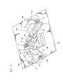
- the fixing device 42 is formed as shown in FIG. 5.
- the fixing device 40 shown in FIG. 5 is for a left-handed person.
- the fixing device 40 comprises a thumb fixing member 40a and an index finger fixing member 40b that are provided on a base plate 58.
- the thumb and index finger fixing members 40a and 40b are widened from each other at a predetermined angle.
- One section of the thumb fixing member 40a is fixed on the base plate 58 by a bolt 72 while the other section of the thumb fixing member 40b is pivotable at a predetermined angle base plated on the fixed section.
- One section of the index finger fixing member 40b is fixed near the thumb fixing member 40a on the base plate 40a by a bolt (not shown), and the other section of the index finger fixing member 40b is pivotable by a predetermined angle with respect to a base plated on the fixed section.
- the photo-guider 46 is disposed between the thumb and index finger fixing members 40a and 40b, and the heater 46a is formed on the surface of the photo-guider 46.
- the tissue 90 between the thumb F1 and the index finger F2 is disposed on a top of the photo-guider 46 to cover a light emission hole through which the light is emitted.
- a first region A1 of the tissue 90 is located on the center of the light emission hole.
- the first region A1 is a region through which the light emitted from the light emission hole passes to allow the absorbance for measuring the blood component to be measured.
- the predetermined tension is set as high as possible within a range where the examinee does not feel the pain so that the absorbance can be more accurately measured by forming the thickness of the tissue 90 as thin as possible.
- the thickness of the tissue can be further reduced by applying a predetermined pressure to a predetermined region of the tissue 90 such as second and third regions A2 and A3.
- the pressure can be applied to one of or both the second and third regions A2 and A3.
- the pressure can be applied to depress the second and third regions A2 and A3 downward or to pull the same frontward.
- the thumb fixing member 40a comprises a first support 60 having a first section fixed on the base plate 58 and a second section pivotable base plated on the fixed portion and a movable member 62 supported by the first support 60 to adjust a space of a thumb receiving region 66.
- the movable member 62 is designed to move in a direction where the thumb receiving region 66 can be lengthened or shortened in accordance with a length of the thumb and to move in a direction where the thumb receiving region 66 can be widened or narrowed in accordance with a thickness of the thumb.
- a first adjustor 68 is provided on, for example, one end of the first support 60.
- the first adjustor 68 moves the movable member 62 so that the thumb receiving region 66 can meet the length of the thumb.
- a second adjustor 70 is provided on, for example, one side of the movable member 62. While rotating clockwise or counterclockwise, the second adjustor 70 adjusts the thumb receiving region 66 such that the thumb receiving region 66 can be widened or narrowed in response to the thickness of the thumb.
- the reference numeral 64 indicates a first pressing member for applying pressure to the second region A1.
- the first pressing member 64 is pivotally fixed in a vertical direction.
- the first pressing member 64 is first pivoted upward so that the thumb can received in the thumb receiving region 66, after which the first pressing member 64 is pivoted downward to apply predetermined force to the second region A2 of the tissue 90 shown in FIG. 6).
- a stopper (not shown) for stopping the thumb fixing member 40a from pivoting at a predetermined angle may be placed under the second adjustor 70.
- the index finger fixing member 40b comprises an index finger support 76 for receiving the index finger, tissue catchers 78 and 80 for fixing the third region A3 of the tissue 90 shown in FIG. 6, a movable member 82 for moving the tissue catchers 78 and 80, and a second support 74 for supporting these elements.
- the ) second support 74 is pivotally fixed on the base plate 58.
- the index finger support 76 is designed to be movable in response to a length of the index finger.
- a third adjustor 84 is provided on one end of the second support 74. While rotating clockwise or counterclockwise, the third adjustor 84 moves the index finger support 76 toward or away from a fixing portion of the second support 74.
- First corresponding ends of the tissue catchers 78 and 80 contact each other when the tissue 90 is not fitted between them.
- the thumb F1 and the index finger F2 are respectively placed in the thumb and index finger fixing members 40a and 40b, second corresponding ends of the tissue catchers 78 and 80, which are opposite to the first corresponding ends, are pushed to thereby define a predetermined gap between the first corresponding ends of the tissue catchers 78 and 80.
- the third region A3 of the tissue 90 is fitted in the gap defined between the first corresponding ends of the tissue catchers 78 and 80, after which, when the pushing force is released, the third region A3 of the tissue 90 is fixed by a pressing force of the tissue catchers 78 and 80.
- the tissue catchers 78 and 80 are disposed on an identical line where the movable member 82 is disposed so that the tissue catchers 78 and 80 can move in a direction where the movable member 82 moves.
- there is a need for providing predetermined tension to the tissue 90 That is, after the third region A3 of the tissue 90 is fixed between the tissue catchers 78 and 80, the tissue catchers 78 and 80 are moved away from the tissue 90 by moving the movable member 82 outward to apply the tension to the tissue 90.
- a stopper not shown
- a stopper release member not shown
- the stopper is released by the stopper release member.
- the second support 74 on which the tissue catchers 78 and 80, the movable member 82 and the index finger support 76 are mounted is pivoted at a predetermined angle
- the second support 74 is maintained at its pivoted angle by a stopper 86.
- the stopper 86 allows the second support 74 to be screw-coupled on the base plate 58,
- the reference numeral 88 in FIG. 8 indicates a base plate for attaching the photo-guider 46 to the light source (44 in FIG. 4) disposed under the photo guider 46.
- the thumb and index finger fixing members 40a and 40b and the photo-guider 46 can be mounted on a single base plate attached on the light source 44.
- a single base plate provided with a hole through which the photo-guider 46 passes and on which the thumb and index finger fixing members 40a and 40b are mounted can be attached on the light source 44.
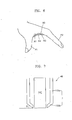
- the photo-detector 48 contacting the top of the first region A1 of the tissue 90, as shown in FIG. 7, comprises a photo-guide pillar 100 and a protecting tube 102 disposed at a predetermined interval around the photo-guide pillar 100.
- the photo-guide pillar 100 functions to guide the light emitted from the photo-guider 46 and transmit the first region A1 of the tissue 90 to the amplifier 50.
- the photo-guide pillar 100 is formed in a cylindrical shape of circular or oval sections, or a prism, preferably, in a rectangular prism.
- the protecting tube 102 protects the photo-guide pillar 100 and makes an interfacing area between the photo-detector 48 and the first region A1 gentle.
- the protecting tube 102 comprises a portion 102a in parallel with the photo-guide pillar 100 and a portion 102b bent from the parallel portion 102a toward a lower end of the photo-guide pillar 100.
- the bent portion 102b extends to almost reach the photo-guide pillar 100.
- the bent portion 102b is inclined at a predetermined angle ⁇ with respect to a horizontal plane on which a bottom of the photo-guide pillar 100 is disposed.
- the predetermined inclined angle ⁇ be equal to or less than 60°, more preferably, be in a range of 30-60 °.
- the inclined angle may be varied.
- a hand fixing member may be further provided. That is, in a state where the thumb F1 and the index finger F2 are respectively fixed on the thumb and index finger fixing members 40a and 40b, the hand, for example, a wrist can be fixed by the hand fixing member.
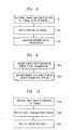
- the blood component measuring method of the present invention is comprises of first to third operations S1, S2, and S3.
- the first operation S1 is for adjusting a temperature of the tissue to be examined of the examinee (i.e., the first region A1 of the tissue 90 shown in FIG. 6) to a predetermined temperature.
- the temperature of the tissue to be examined is adjusted by the heater 46a provided on the photo-guider 46.
- the temperature of the tissue to be examined is uniformly maintained in a range of, for example, 36-40 °C.
- the thumb F1 and the index finger F1 are respectively fixed on the thumb and index finger fixing members 40a and 40b and the tissue 90 between the thumb F1 and the index finger F1 is located on the top of the photo-guider 46, in the course of which, by operating the first to third adjustors 68, 70 and 84, the thumb and the index finger are comfortably fixed on the thumb and index finger fixing members 40a and 40b.
- the hand fixing member the hand (the wrist) can be also fixed.
- the second operation S2 is for adjusting tension of the tissue to be examined to a predetermined level.
- the order of performing the first and second operations S1 and S2 can be changed. That is, after the tension of the tissue to be examined is adjusted, the temperature of the same can be adjusted.
- FIG. 9 shows a detailed process of the second operation S2.
- the second operation S2 includes an operation S2a for spreading the tissue to be examined at a predetermined angle and an operation S2b for deforming the tissue to be examined in a direction where the tension occurs.
- the spreading of the tissue to be examined can be varied according to a kind of the tissue to be examined.
- the tissue to be examined is the tissue 90 between the thumb F1 and the index finger F2
- the tissues 90 of the examinees may be different in a thickness from each other. Accordingly, it is preferable that the opening angle between the thumb F1 and the index finger F2 is varied according to each individual.
- the measuring condition of the tissue 90 be identically maintained.
- tissue to be examined is already, there is a need for further applying a tension to the tissue to be examined to adjust, for example, a thickness of the same.
- a predetermined force is applied to a specific region, for example, to the second region A2 of the tissue 90 using the first pressing member 64.
- the second region A2 of the tissue 90 is depressed downward, thereby applying the tension to the tissue 90.
- a pulling force is applied to the third region A3 using the tissue catchers 78 and 80.
- the tension is applied to the tissue 90.
- the first and second methods can be simultaneously used. That is, the pressing force can be applied to the second region A2 of the tissue 90 while the pulling force is applied to the third region A3 by the tissue catchers 78 and 80.
- a second tissue catcher (not shown) similar to the tissue catchers 78 and 80 can be used to full the second region A2.
- the third operation S3 can be sub-divided into three operations as shown in Fig. 10.
- the third operation S3 includes: an operation S3a for irradiating light to the tissue to be examined, an operation S3b for detecting light transmitting the tissue to be examined, and an operation S3c for analysing the light detected in the operation S3b.
- the light is irradiated to the bottom of the tissue to be examined (i.e., a bottom of the first region A1 shown in Fig. 6), which contacts the top of the photo-guider 46. At this point, it is preferable that the light is of the near infrared ray.
- the photo-detector 48 closely contacts the top of the tissue to be examined, facing the photo-guider 46 (see FIG. 7). In this state, the photo-detector 48 detects the light containing blood component information in the tissue to be examined, the light being irradiated from the photo-guider 46 and passing through the tissue to be examined.
- a thickness of the tissue to be examined can be adjusted by adjusting pressure in the course of closely contacting the photo-detector 48 on the tissue to be examined. At this point, it is preferable that the thickness of the tissue to be examined is adjusted by applying a pressure of 0.5 N/mm 2 .
- the pressure can be varied in accordance with the examinee. For example, when the examinee feels pain by the pressure of 0.5 N/mm 2 applied to the tissue to be examined, it is preferable that the pressure is less than 0.5 N/mm 2 .
- the light detected by the photo-detector 48 is amplified by the amplifier 50.
- the amplified light is analysed by the analyzer 52.
- the analyzer 52 outputs data on the blood components in the tissue to be examined.
- a test for measuring the blood sugar of the tissue 90 depicted in FIG. 6 was performed to demonstrate the advantages of the present invention.
- the absorbance variation is about ⁇ 0.007 Abs. It was further noted that, when the near infrared ray having a wavelength of 2200 nm was used, the absorbance variation was about ⁇ 0.013 Abs.
- the apparatus of the present invention can be used in many applications for measuring a variety of components in the human body not only blood sugar by using light in all bands as well as near infrared rays.
- the apparatus of the present invention is designed to use a reaction between the near infrared ray and the blood components. Therefore, the inventive apparatus can be employed to measure a bio signal such as a pulse and tissue hydration.
- the apparatus of the present invention has an advantage of applying uniform tension to the tissue to be examined, while uniformly maintaining the thickness of the tissue to be examined.
- the contacting portion between a periphery of the photo-detector and the tissue to be examined can be formed having a gentle inclination, and the temperature of the tissue to be examined can be uniformly maintained within a predetermined range. Therefore, when the apparatus of the present invention is used to measure the blood components, the reproducibility with respect to the measuring condition can be enhanced, thereby minimizing the absorbance variation and improving the reliability of blood component data obtained through the analysis of the absorbance.
- the index finger support 76 depicted in FIG. 5 is designed to simply support the index finger, it can be designed to completely enclose the index finger.
- the thumb and index finger fixing members 40a and 40b can be designed to be connected to each other in the form of a mitten. That is, the index finger fixing member 40b can be replaced with a fixing member in which all of fingers except for the thumb can be inserted.
Landscapes
- Health & Medical Sciences (AREA)
- Life Sciences & Earth Sciences (AREA)
- Physics & Mathematics (AREA)
- Medical Informatics (AREA)
- Surgery (AREA)
- Biophysics (AREA)
- Pathology (AREA)
- Engineering & Computer Science (AREA)
- Biomedical Technology (AREA)
- Heart & Thoracic Surgery (AREA)
- Veterinary Medicine (AREA)
- Molecular Biology (AREA)
- Public Health (AREA)
- Animal Behavior & Ethology (AREA)
- General Health & Medical Sciences (AREA)
- Optics & Photonics (AREA)
- Spectroscopy & Molecular Physics (AREA)
- Emergency Medicine (AREA)
- Hematology (AREA)
- Measurement Of The Respiration, Hearing Ability, Form, And Blood Characteristics Of Living Organisms (AREA)
- Investigating Or Analysing Materials By Optical Means (AREA)
Applications Claiming Priority (2)
| Application Number | Priority Date | Filing Date | Title |
|---|---|---|---|
| KR20030064208A KR100624412B1 (ko) | 2003-09-16 | 2003-09-16 | 혈중성분 측정장치 및 이를 이용한 혈중성분측정방법 |
| KR2003064208 | 2003-09-16 |
Publications (2)
| Publication Number | Publication Date |
|---|---|
| EP1516579A1 true EP1516579A1 (fr) | 2005-03-23 |
| EP1516579B1 EP1516579B1 (fr) | 2008-09-24 |
Family
ID=34192233
Family Applications (1)
| Application Number | Title | Priority Date | Filing Date |
|---|---|---|---|
| EP20040255553 Expired - Lifetime EP1516579B1 (fr) | 2003-09-16 | 2004-09-14 | Appareil et procedé pour mesurer des composants sanguins |
Country Status (5)
| Country | Link |
|---|---|
| US (1) | US7289838B2 (fr) |
| EP (1) | EP1516579B1 (fr) |
| JP (1) | JP3977831B2 (fr) |
| KR (1) | KR100624412B1 (fr) |
| DE (1) | DE602004016712D1 (fr) |
Families Citing this family (20)
| Publication number | Priority date | Publication date | Assignee | Title |
|---|---|---|---|---|
| US6591122B2 (en) * | 2001-03-16 | 2003-07-08 | Nellcor Puritan Bennett Incorporated | Device and method for monitoring body fluid and electrolyte disorders |
| US7657292B2 (en) * | 2001-03-16 | 2010-02-02 | Nellcor Puritan Bennett Llc | Method for evaluating extracellular water concentration in tissue |
| US8135448B2 (en) * | 2001-03-16 | 2012-03-13 | Nellcor Puritan Bennett Llc | Systems and methods to assess one or more body fluid metrics |
| US7239902B2 (en) * | 2001-03-16 | 2007-07-03 | Nellor Puritan Bennett Incorporated | Device and method for monitoring body fluid and electrolyte disorders |
| US7657294B2 (en) | 2005-08-08 | 2010-02-02 | Nellcor Puritan Bennett Llc | Compliant diaphragm medical sensor and technique for using the same |
| US7869850B2 (en) | 2005-09-29 | 2011-01-11 | Nellcor Puritan Bennett Llc | Medical sensor for reducing motion artifacts and technique for using the same |
| US7555327B2 (en) | 2005-09-30 | 2009-06-30 | Nellcor Puritan Bennett Llc | Folding medical sensor and technique for using the same |
| US7881762B2 (en) | 2005-09-30 | 2011-02-01 | Nellcor Puritan Bennett Llc | Clip-style medical sensor and technique for using the same |
| JP2007181602A (ja) * | 2006-01-10 | 2007-07-19 | Norikata Taguma | 携帯型血糖値測定装置 |
| US8073518B2 (en) | 2006-05-02 | 2011-12-06 | Nellcor Puritan Bennett Llc | Clip-style medical sensor and technique for using the same |
| US8255025B2 (en) * | 2006-06-09 | 2012-08-28 | Nellcor Puritan Bennett Llc | Bronchial or tracheal tissular water content sensor and system |
| US8145288B2 (en) | 2006-08-22 | 2012-03-27 | Nellcor Puritan Bennett Llc | Medical sensor for reducing signal artifacts and technique for using the same |
| US8180419B2 (en) | 2006-09-27 | 2012-05-15 | Nellcor Puritan Bennett Llc | Tissue hydration estimation by spectral absorption bandwidth measurement |
| US8116852B2 (en) * | 2006-09-29 | 2012-02-14 | Nellcor Puritan Bennett Llc | System and method for detection of skin wounds and compartment syndromes |
| US20080220512A1 (en) * | 2007-03-09 | 2008-09-11 | Nellcor Puritan Bennett Llc | Tunable laser-based spectroscopy system for non-invasively measuring body water content |
| US20080221411A1 (en) * | 2007-03-09 | 2008-09-11 | Nellcor Puritan Bennett Llc | System and method for tissue hydration estimation |
| US8690864B2 (en) * | 2007-03-09 | 2014-04-08 | Covidien Lp | System and method for controlling tissue treatment |
| US8175665B2 (en) * | 2007-03-09 | 2012-05-08 | Nellcor Puritan Bennett Llc | Method and apparatus for spectroscopic tissue analyte measurement |
| US7734321B2 (en) * | 2007-07-13 | 2010-06-08 | All Protect, Llc | Apparatus for non-invasive spectroscopic measurement of analytes, and method of using the same |
| JP7395135B2 (ja) * | 2019-06-28 | 2023-12-11 | Look Tec株式会社 | 血液測定装置 |
Citations (4)
| Publication number | Priority date | Publication date | Assignee | Title |
|---|---|---|---|---|
| US5551422A (en) * | 1992-11-09 | 1996-09-03 | Boehringer Mannheim Gmbh | Method and apparatus for analytical determination of glucose in a biological matrix |
| US6119026A (en) * | 1997-12-04 | 2000-09-12 | Hewlett-Packard Company | Radiation apparatus and method for analysis of analytes in sample |
| WO2003039326A2 (fr) * | 2001-11-07 | 2003-05-15 | Mills Alexander K | Methode de determination en continu et de façon non invasive des caracteristiques physiologiques |
| EP1459679A1 (fr) * | 2003-03-19 | 2004-09-22 | Samsung Electronics Co., Ltd. | Méthode et appareil pour la mesure non-invasive de la concentration d'un composant sanguin |
Family Cites Families (5)
| Publication number | Priority date | Publication date | Assignee | Title |
|---|---|---|---|---|
| WO1999000053A1 (fr) * | 1997-06-27 | 1999-01-07 | Toa Medical Electronics Co., Ltd. | Dispositif permettant d'examiner un organisme vivant et automate permettant d'analyser le sang d'une maniere non invasive au moyen dudit dispositif |
| JP3758824B2 (ja) * | 1997-08-06 | 2006-03-22 | 倉敷紡績株式会社 | 生体の圧力一定化装置 |
| IL124787A0 (en) * | 1998-06-07 | 1999-01-26 | Itamar Medical C M 1997 Ltd | Pressure applicator devices particularly useful for non-invasive detection of medical conditions |
| TW453862B (en) | 1999-08-30 | 2001-09-11 | Cas Medical Systems Inc | Near infrared spectrophotometric monitoring assembly for non-invasive monitoring of blood oxygenation levels in a subjects's body |
| JP2002202258A (ja) | 2000-12-28 | 2002-07-19 | Bios Ikagaku Kenkyusho:Kk | 分光光学的血糖値測定装置 |
-
2003
- 2003-09-16 KR KR20030064208A patent/KR100624412B1/ko not_active Expired - Fee Related
-
2004
- 2004-09-14 EP EP20040255553 patent/EP1516579B1/fr not_active Expired - Lifetime
- 2004-09-14 DE DE200460016712 patent/DE602004016712D1/de not_active Expired - Lifetime
- 2004-09-16 JP JP2004270346A patent/JP3977831B2/ja not_active Expired - Fee Related
- 2004-09-16 US US10/942,091 patent/US7289838B2/en not_active Expired - Fee Related
Patent Citations (4)
| Publication number | Priority date | Publication date | Assignee | Title |
|---|---|---|---|---|
| US5551422A (en) * | 1992-11-09 | 1996-09-03 | Boehringer Mannheim Gmbh | Method and apparatus for analytical determination of glucose in a biological matrix |
| US6119026A (en) * | 1997-12-04 | 2000-09-12 | Hewlett-Packard Company | Radiation apparatus and method for analysis of analytes in sample |
| WO2003039326A2 (fr) * | 2001-11-07 | 2003-05-15 | Mills Alexander K | Methode de determination en continu et de façon non invasive des caracteristiques physiologiques |
| EP1459679A1 (fr) * | 2003-03-19 | 2004-09-22 | Samsung Electronics Co., Ltd. | Méthode et appareil pour la mesure non-invasive de la concentration d'un composant sanguin |
Also Published As
| Publication number | Publication date |
|---|---|
| KR100624412B1 (ko) | 2006-09-18 |
| JP2005087740A (ja) | 2005-04-07 |
| JP3977831B2 (ja) | 2007-09-19 |
| US20050119538A1 (en) | 2005-06-02 |
| EP1516579B1 (fr) | 2008-09-24 |
| US7289838B2 (en) | 2007-10-30 |
| KR20050027827A (ko) | 2005-03-21 |
| DE602004016712D1 (de) | 2008-11-06 |
Similar Documents
| Publication | Publication Date | Title |
|---|---|---|
| EP1516579B1 (fr) | Appareil et procedé pour mesurer des composants sanguins | |
| CN1822792B (zh) | 用于体液的分析器械和分析方法 | |
| EP0545987B1 (fr) | Dispositif de reception d'un doigt | |
| KR100634500B1 (ko) | 비침습적 체내성분 측정장치 및 방법 | |
| US9554741B2 (en) | Precision depth control lancing tip | |
| US7211052B2 (en) | Flexible test strip lancet device | |
| US6285448B1 (en) | Clinical analyte determination by infrared spectroscopy | |
| US7333186B2 (en) | Method and device for measuring biological information | |
| JP3994588B2 (ja) | 非侵襲血糖計 | |
| US20030010898A1 (en) | System for measuring a biological parameter by means of photoacoustic interaction | |
| JP2005501591A (ja) | 体液をサンプリングする際に使用するための滲出方法および構造体 | |
| US10092209B2 (en) | Non-invasive in situ glucose level sensing using electromagnetic radiation | |
| JP2005013597A (ja) | 生体情報計測装置及び被検体から生体情報を計測する方法 | |
| JPH11188009A (ja) | 生体計測方法と生体計測装置 | |
| US20090018417A1 (en) | Apparatus monitoring signal in situ | |
| JPH07136151A (ja) | 血液成分の濃度を検出する方法及び装置並びにこの装置を較正するための装置 | |
| KR101961147B1 (ko) | 무채혈 혈당 측정 장치, 이를 이용한 무채혈 혈당 측정 방법 | |
| RU2414854C2 (ru) | Устройство для обеспечения постоянного контактного давления при отборе пробы | |
| JP2005080710A (ja) | 光学的血糖値測定用ピックアップ及びこれを用いた血糖値測定方法 | |
| CN118490219A (zh) | 血液测定装置 | |
| US20140323834A1 (en) | Apparatus monitoring signal in situ | |
| US9149217B1 (en) | Apparatus monitoring signal in situ | |
| JP2004294075A (ja) | グルコース濃度測定装置 | |
| JPH0728860B2 (ja) | 血液成分の分光特性測定装置 | |
| WO1996013203A1 (fr) | Procede non invasif de mesure d'analytes dans le sang |
Legal Events
| Date | Code | Title | Description |
|---|---|---|---|
| PUAI | Public reference made under article 153(3) epc to a published international application that has entered the european phase |
Free format text: ORIGINAL CODE: 0009012 |
|
| 17P | Request for examination filed |
Effective date: 20041006 |
|
| AK | Designated contracting states |
Kind code of ref document: A1 Designated state(s): AT BE BG CH CY CZ DE DK EE ES FI FR GB GR HU IE IT LI LU MC NL PL PT RO SE SI SK TR |
|
| AX | Request for extension of the european patent |
Extension state: AL HR LT LV MK |
|
| RIN1 | Information on inventor provided before grant (corrected) |
Inventor name: HWANG, IN-DUK Inventor name: JEON, KYE-JIN Inventor name: CHOE, EUN-YOUNG Inventor name: KIM, HYE-JEONG,SAMSUNG ADVANCED INST. OF TECH. |
|
| AKX | Designation fees paid |
Designated state(s): DE FR GB |
|
| 17Q | First examination report despatched |
Effective date: 20070118 |
|
| GRAP | Despatch of communication of intention to grant a patent |
Free format text: ORIGINAL CODE: EPIDOSNIGR1 |
|
| GRAS | Grant fee paid |
Free format text: ORIGINAL CODE: EPIDOSNIGR3 |
|
| GRAA | (expected) grant |
Free format text: ORIGINAL CODE: 0009210 |
|
| AK | Designated contracting states |
Kind code of ref document: B1 Designated state(s): DE FR GB |
|
| REG | Reference to a national code |
Ref country code: GB Ref legal event code: FG4D |
|
| REF | Corresponds to: |
Ref document number: 602004016712 Country of ref document: DE Date of ref document: 20081106 Kind code of ref document: P |
|
| PLBE | No opposition filed within time limit |
Free format text: ORIGINAL CODE: 0009261 |
|
| STAA | Information on the status of an ep patent application or granted ep patent |
Free format text: STATUS: NO OPPOSITION FILED WITHIN TIME LIMIT |
|
| 26N | No opposition filed |
Effective date: 20090625 |
|
| REG | Reference to a national code |
Ref country code: FR Ref legal event code: PLFP Year of fee payment: 13 |
|
| PGFP | Annual fee paid to national office [announced via postgrant information from national office to epo] |
Ref country code: GB Payment date: 20160914 Year of fee payment: 13 Ref country code: DE Payment date: 20160907 Year of fee payment: 13 |
|
| PGFP | Annual fee paid to national office [announced via postgrant information from national office to epo] |
Ref country code: FR Payment date: 20160826 Year of fee payment: 13 |
|
| REG | Reference to a national code |
Ref country code: DE Ref legal event code: R119 Ref document number: 602004016712 Country of ref document: DE |
|
| GBPC | Gb: european patent ceased through non-payment of renewal fee |
Effective date: 20170914 |
|
| REG | Reference to a national code |
Ref country code: FR Ref legal event code: ST Effective date: 20180531 |
|
| PG25 | Lapsed in a contracting state [announced via postgrant information from national office to epo] |
Ref country code: GB Free format text: LAPSE BECAUSE OF NON-PAYMENT OF DUE FEES Effective date: 20170914 Ref country code: DE Free format text: LAPSE BECAUSE OF NON-PAYMENT OF DUE FEES Effective date: 20180404 |
|
| PG25 | Lapsed in a contracting state [announced via postgrant information from national office to epo] |
Ref country code: FR Free format text: LAPSE BECAUSE OF NON-PAYMENT OF DUE FEES Effective date: 20171002 |