EP1516594A1 - Système d'aspiration unitaire dentaire portable - Google Patents
Système d'aspiration unitaire dentaire portable Download PDFInfo
- Publication number
- EP1516594A1 EP1516594A1 EP03388062A EP03388062A EP1516594A1 EP 1516594 A1 EP1516594 A1 EP 1516594A1 EP 03388062 A EP03388062 A EP 03388062A EP 03388062 A EP03388062 A EP 03388062A EP 1516594 A1 EP1516594 A1 EP 1516594A1
- Authority
- EP
- European Patent Office
- Prior art keywords
- mbar
- housing
- vacuum pump
- inlet
- outlet
- Prior art date
- Legal status (The legal status is an assumption and is not a legal conclusion. Google has not performed a legal analysis and makes no representation as to the accuracy of the status listed.)
- Withdrawn
Links
- 239000012530 fluid Substances 0.000 claims abstract description 21
- 239000002245 particle Substances 0.000 claims abstract description 14
- 238000004891 communication Methods 0.000 claims abstract description 8
- 239000007788 liquid Substances 0.000 claims description 12
- 241000894006 Bacteria Species 0.000 claims description 7
- 210000003296 saliva Anatomy 0.000 description 7
- 238000000034 method Methods 0.000 description 6
- 210000000214 mouth Anatomy 0.000 description 5
- 230000006378 damage Effects 0.000 description 4
- 208000027418 Wounds and injury Diseases 0.000 description 3
- 208000014674 injury Diseases 0.000 description 3
- 235000019504 cigarettes Nutrition 0.000 description 2
- 238000004140 cleaning Methods 0.000 description 2
- 238000010586 diagram Methods 0.000 description 2
- 238000005259 measurement Methods 0.000 description 2
- 238000012544 monitoring process Methods 0.000 description 2
- XLYOFNOQVPJJNP-UHFFFAOYSA-N water Substances O XLYOFNOQVPJJNP-UHFFFAOYSA-N 0.000 description 2
- 240000006108 Allium ampeloprasum Species 0.000 description 1
- 235000005254 Allium ampeloprasum Nutrition 0.000 description 1
- 206010003497 Asphyxia Diseases 0.000 description 1
- 241000589248 Legionella Species 0.000 description 1
- 206010035148 Plague Diseases 0.000 description 1
- 241000607479 Yersinia pestis Species 0.000 description 1
- 239000011324 bead Substances 0.000 description 1
- 239000008280 blood Substances 0.000 description 1
- 210000004369 blood Anatomy 0.000 description 1
- 230000006835 compression Effects 0.000 description 1
- 238000007906 compression Methods 0.000 description 1
- 238000013461 design Methods 0.000 description 1
- 238000001914 filtration Methods 0.000 description 1
- 235000013305 food Nutrition 0.000 description 1
- 210000004195 gingiva Anatomy 0.000 description 1
- 230000003902 lesion Effects 0.000 description 1
- 239000000463 material Substances 0.000 description 1
- 230000000474 nursing effect Effects 0.000 description 1
- 230000002093 peripheral effect Effects 0.000 description 1
- 238000005498 polishing Methods 0.000 description 1
- 239000007787 solid Substances 0.000 description 1
- 239000002910 solid waste Substances 0.000 description 1
- 230000000007 visual effect Effects 0.000 description 1
Images




Classifications
-
- A—HUMAN NECESSITIES
- A61—MEDICAL OR VETERINARY SCIENCE; HYGIENE
- A61C—DENTISTRY; APPARATUS OR METHODS FOR ORAL OR DENTAL HYGIENE
- A61C17/00—Devices for cleaning, polishing, rinsing or drying teeth, teeth cavities or prostheses; Saliva removers; Dental appliances for receiving spittle
- A61C17/06—Saliva removers; Accessories therefor
- A61C17/065—Saliva removers; Accessories therefor characterised by provisions for processing the collected matter, e.g. for separating solids or air
-
- A—HUMAN NECESSITIES
- A61—MEDICAL OR VETERINARY SCIENCE; HYGIENE
- A61C—DENTISTRY; APPARATUS OR METHODS FOR ORAL OR DENTAL HYGIENE
- A61C1/00—Dental machines for boring or cutting ; General features of dental machines or apparatus, e.g. hand-piece design
- A61C1/0053—Portable units
Definitions
- the present invention relates to portable dental apparatuses suitable for removing saliva and other fluids by suction during dental procedures.
- the portable dental suction apparatuses enables a visiting dentist to perform dental procedures in places such as nursing homes, hospital emergency rooms or other places with or without a mains power supply, also organisations such as the Red Cross, military or missionaries at operating in remote locations. Other uses may include suction for avoiding suffocation or constriction of people in car crashes or other accidents.
- the requirements for the apparatus are a high airflow and a low air pressure in order to avoid causing injuries to the patient during the procedure.
- an air pressure of no more than approx. 50 millibar is best suited for saliva suction equipment, an air pressure higher than 50 millibar is known to have caused injuries to the gingiva.
- the creation of a high airflow is usually followed by an equally high pressure.
- the present invention seeks to provide a solution wherein a combination of a high airflow and a low air pressure is present.
- the present invention provides a vacuum pump creating a high airflow and also a relatively high air pressure, however it has been realised that combining a vacuum pump creating a high airflow and a high pressure combined with an appropriate filter and a cyclone separator it is possible to create a suction device with a high airflow and an air pressure below 50 millibar, thereby enabling a dentist or surgeon to safely remove saliva, water and other fluids from the oral cavity of a patient.
- a unitary portable power suction system for dental use comprises:
- the power supply may be a battery power supply or a mains power supply or a combination thereof.
- the present invention seeks to provide a high power suction unit that is preferably portable or mobile, and as such should be able to function in an environment without immediate access to a mains supply, however when performing dental treatment near a mains supply, a longer period of operation is attainable by supplying power from a mains supply, also the power supply should be connectable to any mains supply, e.g. 230 VAC, 50 Hz and 110 VAC, 60Hz.
- the cyclone separator may be included in the housing.
- the separator may be included in the housing.
- the cyclone separator constitutes a separate component to be mounted exterior relative to the housing and has a tube for establishing the fluid communication with the vacuum pump inlet.
- the housing has a housing air inlet and a housing air outlet, the housing air inlet being constituted by the vacuum pump inlet, and the housing outlet being constituted by the filter outlet.
- the filter outputs the air from the power suction unit into the surrounding environment.
- the filter means is constituted by a HEPA filter element separating particles including bacteria, such as legionella bacteria, having a size in excess of 8-16 ⁇ m.
- the size of the particles allowed to pass through the filter may be varied by varying the mesh of the filter, but when doing so it is necessary to contemplate the impact on the over-all pressure drop of the system. Since the filter outputs the air from the power suction unit into the surrounding environment the filter should be able to remove particles such as bacteria. Also the filter may remove particles causing smell or odour inconveniences.
- the filter means is a replaceable filter means, preferably a disposable filter means.
- the filter means may at some point be filled with particles removed from the air flow and need replacement or alternatively cleaning.
- the vacuum pump includes a motor housing and a rotor having at least 4 blades, such as 4-8, 8-10, 10-12, 12-16, preferably 6 or 8, the rotor being received in the motor housing in a low-leak fitting.
- the term low-leak fitting defines a rotary pump having the capability of creating a substantial load-independent suction pressure and may be accomplished by the provision of a rotary pump having at the air outlet of the pump a low axial and a low radial clearance between the rotor and the motor housing such as a clearance in the order of 5-10/100 mm.
- the high volume and high pressure pump may be provided even with a fairly low number of rotor blades such as six or eight rotor blades.
- an eight feature of the present invention further comprises a liquid receptor to be connected to the cyclone separator for receiving liquid separated from the air flow by means of the cyclone separator.
- the liquid receptor may have a valve or the like for emptying the contents when needed.
- the liquid receptor is detachable from the cyclone separator.
- the power suction unit 10 comprises a main pump, such as a vacuum pump for the creation of a suction flow.
- the vacuum pump 12 needs to create a high suction flow in the presently preferred embodiment.
- the vacuum pump 12 delivers a suction flow of approximately 1250 litres per minute at a pressure of 150 millibar. However, this pressure is much too powerful for dental use, since a vacuum of this magnitude would probably lead to lesions in the oral cavity of the patient exposed to a suction of this magnitude.
- a filter 14 is mounted in the housing 16 and received air outputted from the vacuum pump 12.
- the filter 14 is adapted for removing dry particles such as bacteria from the airflow prior to the release of the air into the surrounding environment.
- the filter 14 is preferably dimensioned to obtaining a pressure crop of approximately 100 millibar. Attaching a hand piece via a hose to the tube 18 enables a dentist to remove fluids and possibly solid waste elements such as saliva and particles found naturally in the mouth including bacteria, particles of food and dental plague and possibly materials used by the dentist for polishing or cleaning teeth.
- power inlets 20, 22 are placed for connection to external power sources such as car batteries, e.g. via the cigarette lighter outlet or aother DC outlet of a car having 12V, 24V or 48V battery supply, or via 22 to a mains power supply feeding the power suction unit 10 with AC power, e.g. 110 VAC, 60 Hz, or 230 VAC, 50 Hz.
- the housing further comprises switches or buttons 24, 26 for operating the power suction unit 10. The buttons 24, 26 may be used for controlling the level of the airflow through the power suction unit 10.
- the housing 16 includes an aperture 28 connected to the tube 18, where the aperture 28 constitutes the air inlet of the power suction unit 10.
- the filter 14 constitutes the air outlet of the power section unit 10.
- the filter 14 is a HEPA filter filtering particles such as bacteria from the air emitted by the vacuum pump 12.
- the HEPA filter has a mesh size of 8-16 ⁇ m and is thereby able to remove the bacteria collected by the dentist using the power suction unit 10.
- the filter 14 is preferably a replaceable filter and access to the filter is obtained by removing the end closure or end shield 50.
- the end closure 50 may be detached from the housing by sliding the end closure 50 upwards or downwards.
- the end closure 50 may be fastened on either side top or bottom by hinges or the like, thereby enabling the dentist or possibly a service technician to replace the filter 14 by opening the end closure 50 in a manner similar to opening a door.
- the end closure 48 placed opposite the end closure 50 may also be opened or removed in a manner similar to that of the end closure 50. Opening the end closure 48 may enable a dentist or service technician to obtain access to fuses 62.
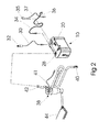
- Fig. 2 is a schematic view of the power suction unit 10 and a number of peripherals e.g. a power cord 30 having a connector 32 for connecting the power cord 30 to a car battery, such as a 12V, 24V or 48V battery, via the cigarette lighter output or other DC outlet.
- the power cord 30 is connected to the power inlet 20, which in turn is connected to a power supply unit mounted inside the power suction unit 10.
- Another power cord 34 may be used to power the power supply in the power suction unit 10 from a power source such as 110 VAC, 60 Hz, or 230 VAC, 50 Hz.
- the power cord 34 may have a fixed connector 36 capable of connecting to a specific outlet design used in a specific country.
- the connector 36 may be detachable and a number of connectors may be supplied with the power suction unit 10 enabling a user to connect the power suction unit 10 to any type of socket in the world.
- the power suction unit 10 may be powered by a battery.
- the battery is preferably rechargeable and may include or be connectable to a solar cell system or a mains supply for recharging the battery.
- a separator 38 having an inlet 40, and outlet 42, and a fluid collecting reservoir 44 are connected to the aperture 28 of the power suction unit 10.
- the inlet 40 receives air from dental equipment such as a suction unit operated by a dentist.
- the separator 38 separates fluids such as saliva and/or other fluids including blood, solid particles etc., from the air flow received through the inlet 40, by separating the fluids into the fluid collecting reservoir 44 and passing the air through the outlet 42 into the power suction unit 10.
- the separator 38, the inlet 40, the outlet 42 and/or the collecting reservoir 44 may be built in or incorporated into the housing 16 of the power suction unit 10, alternatively any combination thereof.
- the separator 38 is further provided with an electrical conductivity measuring circuitry included in the housing of the separator.
- the circuitry serves the purpose of detecting the presence of air/liquid in the separator and to supply an electrical signal representing the presence of liquid rather than air exclusively in the separator to the power suction unit 10 through an electric cord 41.
- an electrical signal indicating air within the separator 38 exclusively the power suction unit 10 is turned off.
- the presence of liquid in the separator which causes an increase in the conductivity through the separator is detected by the electrical conductivity monitoring circuitry and results in the supply of an electrical signal in the cord 41 to the power suction unit 10, instruction the power suction unit 10 to turn on.
- a handle 35 for the support of a suction device is shown which handle like the separator 38 is provided with an internal electrical conductivity monitoring or measuring circuitry for the supply of an electrical signal representing the presence of liquid or air to the power suction unit 10 through an electric cord 37.
- an electrical conductivity monitoring or measuring circuitry for the supply of an electrical signal representing the presence of liquid or air to the power suction unit 10 through an electric cord 37.
- the separator 38, the collecting reservoir 44 and the power suction unit 10 may be placed in a container such as a suitcase-like container for easier transportation of the aggregated system.
- the suitcase may comprise a battery for powering the power suction unit 10 and possibly the separator 38.
- the vacuum pump 12 may be constituted by a rotor blade wheel or the like encased in a closely fitting housing for obtaining the required air pressure.
- the collecting reservoir 44 may be fitted with a valve or tap for emptying the collecting reservoir 44 when the reservoir is near its maximum capacity.
- the collecting reservoir 44 may include sensors for alerting the dentist or operator when the collecting reservoir 44 is near a specific level such as when the reservoir is at least 75% filled, preferably when the reservoir is 90% filled.
- the collecting reservoir 44 may then signal the dentist or operator either with an audible alarm or a visual indication such as by lighting a light-emitting diode (led) or lamp, alternatively a combination of these.
- a second exploded view of the power suction unit 10 is shown.
- the filter 14 is mounted in a filter box 52 for easy fixation in an aperture 54 of the housing 16.
- the power supply 46 is shown detached from the inside of the housing 16 and is preferably mounted opposite the filter 14.
- a transformer constituted by the elements shown inside the dotted line 56 is also mounted inside the housing 16 in the end opposite the filter.
- Also included in the housing 16 a main power switch 58 having a button on the outside of the housing 16 for turning on or switching off the power to the power suction unit 10.
- the placement of the power supply 46 as show in Fig. 1, the transformer and the vacuum 12 is chosen for distributing the weight within the housing 16 in a way such that a person carrying the power suction unit 10 by lifting the handle 60 does not feel discomfort when carrying the power suction unit 10.
- the separator 38 and the power suction unit 10 includes resistive conductivity measurement devices for the registration of presence of water or air, in the case of air exclusively the apparatus is turned off.
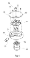
- the vacuum pump 12 in the presently preferred embodiment of the present invention includes an electric motor 64 mounted on a housing 66.
- the housing 66 includes an aperture 68 for receiving a connecting piece 70 for outputting air from the vacuum pump 12.
- a projecting wall bead 72 extends from the inside of the housing towards a blade wheel 74, thereby creating a narrow gap between the wall and the blade wheel 74 in the order of 5-10/100 mm radially and axially.
- the narrow gap between the housing wall and the blade wheel 74 constitutes the low leek required to obtaining a high air flow and a high air pressure.
- the blade wheel 74 is engaged by a rotary shaft 76 from the electric motor 64.
- the blade wheel 74 is enclosed in the housing 66 by a lid 78, which includes an aperture 80 adapted for receiving a connecting piece 82 for letting air into the vacuum pump 12.
- the lid 78 is preferably slightly angled or tilted having its lower point near the aperture 68, thereby obtaining a compression of the air.
- a prototype version of the present invention has been constructed and has obtained an airflow at the system inlet of 420 I/min. and having an air pressure of 53 millibar.
- Fig. 5 and 6 are schematic diagrams illustrating electrical circuits of the power suction system, the figures are self-explanatory and no detailed description is provided presently.
Landscapes
- Health & Medical Sciences (AREA)
- Dentistry (AREA)
- Epidemiology (AREA)
- Life Sciences & Earth Sciences (AREA)
- Animal Behavior & Ethology (AREA)
- General Health & Medical Sciences (AREA)
- Public Health (AREA)
- Veterinary Medicine (AREA)
- Cyclones (AREA)
Priority Applications (1)
| Application Number | Priority Date | Filing Date | Title |
|---|---|---|---|
| EP03388062A EP1516594A1 (fr) | 2003-09-18 | 2003-09-18 | Système d'aspiration unitaire dentaire portable |
Applications Claiming Priority (1)
| Application Number | Priority Date | Filing Date | Title |
|---|---|---|---|
| EP03388062A EP1516594A1 (fr) | 2003-09-18 | 2003-09-18 | Système d'aspiration unitaire dentaire portable |
Publications (1)
| Publication Number | Publication Date |
|---|---|
| EP1516594A1 true EP1516594A1 (fr) | 2005-03-23 |
Family
ID=34178670
Family Applications (1)
| Application Number | Title | Priority Date | Filing Date |
|---|---|---|---|
| EP03388062A Withdrawn EP1516594A1 (fr) | 2003-09-18 | 2003-09-18 | Système d'aspiration unitaire dentaire portable |
Country Status (1)
| Country | Link |
|---|---|
| EP (1) | EP1516594A1 (fr) |
Cited By (1)
| Publication number | Priority date | Publication date | Assignee | Title |
|---|---|---|---|---|
| CN114729650A (zh) * | 2019-11-08 | 2022-07-08 | 布鲁诺·普瑞根泽 | 牙科排空器 |
Citations (13)
| Publication number | Priority date | Publication date | Assignee | Title |
|---|---|---|---|---|
| US2864166A (en) * | 1955-05-18 | 1958-12-16 | Torit Mfg Company | Evacuator for dental use |
| US3081542A (en) | 1959-12-18 | 1963-03-19 | William E Sherfey | Mobile dental unit |
| GB1106858A (en) * | 1965-11-01 | 1968-03-20 | Electrolux Ab | Aspirator apparatus for dental purposes |
| GB1251915A (fr) * | 1970-03-03 | 1971-11-03 | ||
| US4286949A (en) | 1980-02-15 | 1981-09-01 | Holt Jr Raleigh A | Portable dental apparatus |
| US4373699A (en) | 1980-05-15 | 1983-02-15 | Sybron Corporation | Fluid flow control valve for dental instruments |
| US5211558A (en) | 1991-11-29 | 1993-05-18 | International Equipment & Supply Corp. | Portable dental workstation |
| US5324197A (en) * | 1993-02-08 | 1994-06-28 | Shain Nat R | Portable power source for dental handpiece illumination |
| US5655905A (en) | 1995-10-12 | 1997-08-12 | Jaimes; Jairo | Mobile multifunctional dental apparatus |
| US5741397A (en) | 1996-01-11 | 1998-04-21 | Kraver; Mark P. | Dental waste separator |
| WO1999020197A1 (fr) * | 1997-10-17 | 1999-04-29 | Midwest Dental Products Corporation | Appareil d'evacuation utilise pendant un acte d'abrasion dentaire |
| US6022326A (en) | 1998-10-30 | 2000-02-08 | Lifepoint, Inc. | Device and method for automatic collection of whole saliva |
| US6217358B1 (en) | 1997-08-08 | 2001-04-17 | Yazaki Corporation | Connector coupling structure |
-
2003
- 2003-09-18 EP EP03388062A patent/EP1516594A1/fr not_active Withdrawn
Patent Citations (13)
| Publication number | Priority date | Publication date | Assignee | Title |
|---|---|---|---|---|
| US2864166A (en) * | 1955-05-18 | 1958-12-16 | Torit Mfg Company | Evacuator for dental use |
| US3081542A (en) | 1959-12-18 | 1963-03-19 | William E Sherfey | Mobile dental unit |
| GB1106858A (en) * | 1965-11-01 | 1968-03-20 | Electrolux Ab | Aspirator apparatus for dental purposes |
| GB1251915A (fr) * | 1970-03-03 | 1971-11-03 | ||
| US4286949A (en) | 1980-02-15 | 1981-09-01 | Holt Jr Raleigh A | Portable dental apparatus |
| US4373699A (en) | 1980-05-15 | 1983-02-15 | Sybron Corporation | Fluid flow control valve for dental instruments |
| US5211558A (en) | 1991-11-29 | 1993-05-18 | International Equipment & Supply Corp. | Portable dental workstation |
| US5324197A (en) * | 1993-02-08 | 1994-06-28 | Shain Nat R | Portable power source for dental handpiece illumination |
| US5655905A (en) | 1995-10-12 | 1997-08-12 | Jaimes; Jairo | Mobile multifunctional dental apparatus |
| US5741397A (en) | 1996-01-11 | 1998-04-21 | Kraver; Mark P. | Dental waste separator |
| US6217358B1 (en) | 1997-08-08 | 2001-04-17 | Yazaki Corporation | Connector coupling structure |
| WO1999020197A1 (fr) * | 1997-10-17 | 1999-04-29 | Midwest Dental Products Corporation | Appareil d'evacuation utilise pendant un acte d'abrasion dentaire |
| US6022326A (en) | 1998-10-30 | 2000-02-08 | Lifepoint, Inc. | Device and method for automatic collection of whole saliva |
Cited By (2)
| Publication number | Priority date | Publication date | Assignee | Title |
|---|---|---|---|---|
| CN114729650A (zh) * | 2019-11-08 | 2022-07-08 | 布鲁诺·普瑞根泽 | 牙科排空器 |
| CN114729650B (zh) * | 2019-11-08 | 2024-05-24 | 布鲁诺·普瑞根泽 | 牙科排空器 |
Similar Documents
| Publication | Publication Date | Title |
|---|---|---|
| JP3223545U (ja) | 集塵裝置 | |
| US6352525B1 (en) | Portable modular chest drainage system | |
| CN101730488B (zh) | 携带包 | |
| AU2010281931B2 (en) | Device that can be worn on the body of a user and that provides vacuum for medical uses | |
| CA2320987A1 (fr) | Appareil d'evacuation d'urine pour les femmes | |
| WO2000025651A1 (fr) | Urinoir portatif a pompe en ligne | |
| US11974659B2 (en) | Toothbrush suction apparatus and method | |
| EP1483012A2 (fr) | Dispositif portatif d'aspiration alimente par batterie | |
| CN211535825U (zh) | 净味杀菌器 | |
| JP2001353213A (ja) | 乳畜機 | |
| US6379149B1 (en) | Dental treatment area | |
| US20240081964A1 (en) | Toothbrush with disposable irrigator | |
| US6652481B1 (en) | Hygienic saliva compensation device with improved handheld and intra-oral collection device | |
| US7465392B1 (en) | Weeder for pond | |
| CN108348661A (zh) | 用于改进医疗吸引器的电气安全性和抽吸性能并避免感染因子散播的装置和方法 | |
| CN214370806U (zh) | 空气净化器 | |
| EP1516594A1 (fr) | Système d'aspiration unitaire dentaire portable | |
| US20120288821A1 (en) | Dental Vacuum | |
| TW201529062A (zh) | 可搬運式牙科診療裝置 | |
| US3486173A (en) | Bedpan with deodorizing means | |
| WO2019147184A1 (fr) | Dispositif d'irrigation de cavité corporelle | |
| KR200459725Y1 (ko) | 의료용 석션장치 | |
| US20230018446A1 (en) | Air purification systems and methods for vacuum cleaners | |
| TWM589564U (zh) | 具殺菌功能的吸鼻器 | |
| JP2001258911A (ja) | 口腔用のバキューム装置、給水装置および洗浄装置 |
Legal Events
| Date | Code | Title | Description |
|---|---|---|---|
| PUAI | Public reference made under article 153(3) epc to a published international application that has entered the european phase |
Free format text: ORIGINAL CODE: 0009012 |
|
| AK | Designated contracting states |
Kind code of ref document: A1 Designated state(s): AT BE BG CH CY CZ DE DK EE ES FI FR GB GR HU IE IT LI LU MC NL PT RO SE SI SK TR |
|
| AX | Request for extension of the european patent |
Extension state: AL LT LV MK |
|
| AKX | Designation fees paid | ||
| REG | Reference to a national code |
Ref country code: DE Ref legal event code: 8566 |
|
| STAA | Information on the status of an ep patent application or granted ep patent |
Free format text: STATUS: THE APPLICATION IS DEEMED TO BE WITHDRAWN |
|
| 18D | Application deemed to be withdrawn |
Effective date: 20050924 |