EP1516603B1 - Satz zum Schneiden eines Innengewindes in Knochen - Google Patents
Satz zum Schneiden eines Innengewindes in Knochen Download PDFInfo
- Publication number
- EP1516603B1 EP1516603B1 EP04255636A EP04255636A EP1516603B1 EP 1516603 B1 EP1516603 B1 EP 1516603B1 EP 04255636 A EP04255636 A EP 04255636A EP 04255636 A EP04255636 A EP 04255636A EP 1516603 B1 EP1516603 B1 EP 1516603B1
- Authority
- EP
- European Patent Office
- Prior art keywords
- tap
- thread
- kit
- diameter
- bone
- Prior art date
- Legal status (The legal status is an assumption and is not a legal conclusion. Google has not performed a legal analysis and makes no representation as to the accuracy of the status listed.)
- Expired - Lifetime
Links
- 210000000988 bone and bone Anatomy 0.000 title claims abstract description 41
- 238000010079 rubber tapping Methods 0.000 claims abstract description 6
- ALEXXDVDDISNDU-JZYPGELDSA-N cortisol 21-acetate Chemical compound C1CC2=CC(=O)CC[C@]2(C)[C@@H]2[C@@H]1[C@@H]1CC[C@@](C(=O)COC(=O)C)(O)[C@@]1(C)C[C@@H]2O ALEXXDVDDISNDU-JZYPGELDSA-N 0.000 claims description 7
- 238000006073 displacement reaction Methods 0.000 claims description 4
- 230000004323 axial length Effects 0.000 claims description 2
- 210000000588 acetabulum Anatomy 0.000 description 33
- 210000001624 hip Anatomy 0.000 description 18
- 239000007858 starting material Substances 0.000 description 15
- 238000000034 method Methods 0.000 description 10
- 230000015572 biosynthetic process Effects 0.000 description 9
- 238000005755 formation reaction Methods 0.000 description 9
- 206010058314 Dysplasia Diseases 0.000 description 4
- 238000006243 chemical reaction Methods 0.000 description 4
- 238000000576 coating method Methods 0.000 description 4
- 229910052588 hydroxylapatite Inorganic materials 0.000 description 4
- XYJRXVWERLGGKC-UHFFFAOYSA-D pentacalcium;hydroxide;triphosphate Chemical compound [OH-].[Ca+2].[Ca+2].[Ca+2].[Ca+2].[Ca+2].[O-]P([O-])([O-])=O.[O-]P([O-])([O-])=O.[O-]P([O-])([O-])=O XYJRXVWERLGGKC-UHFFFAOYSA-D 0.000 description 4
- 238000001356 surgical procedure Methods 0.000 description 4
- 239000011248 coating agent Substances 0.000 description 3
- 238000003780 insertion Methods 0.000 description 3
- 230000037431 insertion Effects 0.000 description 3
- 239000000463 material Substances 0.000 description 3
- 229910000684 Cobalt-chrome Inorganic materials 0.000 description 2
- RTAQQCXQSZGOHL-UHFFFAOYSA-N Titanium Chemical compound [Ti] RTAQQCXQSZGOHL-UHFFFAOYSA-N 0.000 description 2
- 239000004699 Ultra-high molecular weight polyethylene Substances 0.000 description 2
- MCMNRKCIXSYSNV-UHFFFAOYSA-N Zirconium dioxide Chemical compound O=[Zr]=O MCMNRKCIXSYSNV-UHFFFAOYSA-N 0.000 description 2
- WAIPAZQMEIHHTJ-UHFFFAOYSA-N [Cr].[Co] Chemical compound [Cr].[Co] WAIPAZQMEIHHTJ-UHFFFAOYSA-N 0.000 description 2
- 230000008901 benefit Effects 0.000 description 2
- 239000010952 cobalt-chrome Substances 0.000 description 2
- 230000009977 dual effect Effects 0.000 description 2
- 230000013011 mating Effects 0.000 description 2
- 238000002360 preparation method Methods 0.000 description 2
- 239000010936 titanium Substances 0.000 description 2
- 229910052719 titanium Inorganic materials 0.000 description 2
- 229920000785 ultra high molecular weight polyethylene Polymers 0.000 description 2
- 208000008558 Osteophyte Diseases 0.000 description 1
- CODVACFVSVNQPY-UHFFFAOYSA-N [Co].[C] Chemical compound [Co].[C] CODVACFVSVNQPY-UHFFFAOYSA-N 0.000 description 1
- 229910045601 alloy Inorganic materials 0.000 description 1
- 239000000956 alloy Substances 0.000 description 1
- PNEYBMLMFCGWSK-UHFFFAOYSA-N aluminium oxide Inorganic materials [O-2].[O-2].[O-2].[Al+3].[Al+3] PNEYBMLMFCGWSK-UHFFFAOYSA-N 0.000 description 1
- 239000012227 artificial bone substitute Substances 0.000 description 1
- 239000002639 bone cement Substances 0.000 description 1
- 230000037182 bone density Effects 0.000 description 1
- 239000004568 cement Substances 0.000 description 1
- 229910010293 ceramic material Inorganic materials 0.000 description 1
- 230000000295 complement effect Effects 0.000 description 1
- 230000001010 compromised effect Effects 0.000 description 1
- 230000007547 defect Effects 0.000 description 1
- 230000018109 developmental process Effects 0.000 description 1
- 238000005553 drilling Methods 0.000 description 1
- 208000035474 group of disease Diseases 0.000 description 1
- 238000011540 hip replacement Methods 0.000 description 1
- 239000007943 implant Substances 0.000 description 1
- 210000001503 joint Anatomy 0.000 description 1
- 230000007774 longterm Effects 0.000 description 1
- 230000007246 mechanism Effects 0.000 description 1
- 229910052751 metal Inorganic materials 0.000 description 1
- 239000002184 metal Substances 0.000 description 1
- 201000008482 osteoarthritis Diseases 0.000 description 1
- 210000000323 shoulder joint Anatomy 0.000 description 1
- 210000004872 soft tissue Anatomy 0.000 description 1
- 238000011541 total hip replacement Methods 0.000 description 1
Images






Classifications
-
- A—HUMAN NECESSITIES
- A61—MEDICAL OR VETERINARY SCIENCE; HYGIENE
- A61F—FILTERS IMPLANTABLE INTO BLOOD VESSELS; PROSTHESES; DEVICES PROVIDING PATENCY TO, OR PREVENTING COLLAPSING OF, TUBULAR STRUCTURES OF THE BODY, e.g. STENTS; ORTHOPAEDIC, NURSING OR CONTRACEPTIVE DEVICES; FOMENTATION; TREATMENT OR PROTECTION OF EYES OR EARS; BANDAGES, DRESSINGS OR ABSORBENT PADS; FIRST-AID KITS
- A61F2/00—Filters implantable into blood vessels; Prostheses, i.e. artificial substitutes or replacements for parts of the body; Appliances for connecting them with the body; Devices providing patency to, or preventing collapsing of, tubular structures of the body, e.g. stents
- A61F2/02—Prostheses implantable into the body
- A61F2/30—Joints
- A61F2/30721—Accessories
-
- A—HUMAN NECESSITIES
- A61—MEDICAL OR VETERINARY SCIENCE; HYGIENE
- A61B—DIAGNOSIS; SURGERY; IDENTIFICATION
- A61B17/00—Surgical instruments, devices or methods
- A61B17/56—Surgical instruments or methods for treatment of bones or joints; Devices specially adapted therefor
- A61B17/58—Surgical instruments or methods for treatment of bones or joints; Devices specially adapted therefor for osteosynthesis, e.g. bone plates, screws or setting implements
- A61B17/68—Internal fixation devices, including fasteners and spinal fixators, even if a part thereof projects from the skin
- A61B17/84—Fasteners therefor or fasteners being internal fixation devices
- A61B17/86—Pins or screws or threaded wires; nuts therefor
-
- A—HUMAN NECESSITIES
- A61—MEDICAL OR VETERINARY SCIENCE; HYGIENE
- A61B—DIAGNOSIS; SURGERY; IDENTIFICATION
- A61B17/00—Surgical instruments, devices or methods
- A61B17/16—Instruments for performing osteoclasis; Drills or chisels for bones; Trepans
- A61B17/1655—Instruments for performing osteoclasis; Drills or chisels for bones; Trepans for tapping
-
- A—HUMAN NECESSITIES
- A61—MEDICAL OR VETERINARY SCIENCE; HYGIENE
- A61B—DIAGNOSIS; SURGERY; IDENTIFICATION
- A61B17/00—Surgical instruments, devices or methods
- A61B17/16—Instruments for performing osteoclasis; Drills or chisels for bones; Trepans
- A61B17/1662—Instruments for performing osteoclasis; Drills or chisels for bones; Trepans for particular parts of the body
- A61B17/1664—Instruments for performing osteoclasis; Drills or chisels for bones; Trepans for particular parts of the body for the hip
- A61B17/1666—Instruments for performing osteoclasis; Drills or chisels for bones; Trepans for particular parts of the body for the hip for the acetabulum
-
- A—HUMAN NECESSITIES
- A61—MEDICAL OR VETERINARY SCIENCE; HYGIENE
- A61B—DIAGNOSIS; SURGERY; IDENTIFICATION
- A61B17/00—Surgical instruments, devices or methods
- A61B17/16—Instruments for performing osteoclasis; Drills or chisels for bones; Trepans
- A61B17/17—Guides or aligning means for drills, mills, pins or wires
- A61B17/1739—Guides or aligning means for drills, mills, pins or wires specially adapted for particular parts of the body
- A61B17/1742—Guides or aligning means for drills, mills, pins or wires specially adapted for particular parts of the body for the hip
- A61B17/1746—Guides or aligning means for drills, mills, pins or wires specially adapted for particular parts of the body for the hip for the acetabulum
-
- A—HUMAN NECESSITIES
- A61—MEDICAL OR VETERINARY SCIENCE; HYGIENE
- A61B—DIAGNOSIS; SURGERY; IDENTIFICATION
- A61B17/00—Surgical instruments, devices or methods
- A61B17/56—Surgical instruments or methods for treatment of bones or joints; Devices specially adapted therefor
- A61B17/58—Surgical instruments or methods for treatment of bones or joints; Devices specially adapted therefor for osteosynthesis, e.g. bone plates, screws or setting implements
- A61B17/88—Osteosynthesis instruments; Methods or means for implanting or extracting internal or external fixation devices
-
- A—HUMAN NECESSITIES
- A61—MEDICAL OR VETERINARY SCIENCE; HYGIENE
- A61F—FILTERS IMPLANTABLE INTO BLOOD VESSELS; PROSTHESES; DEVICES PROVIDING PATENCY TO, OR PREVENTING COLLAPSING OF, TUBULAR STRUCTURES OF THE BODY, e.g. STENTS; ORTHOPAEDIC, NURSING OR CONTRACEPTIVE DEVICES; FOMENTATION; TREATMENT OR PROTECTION OF EYES OR EARS; BANDAGES, DRESSINGS OR ABSORBENT PADS; FIRST-AID KITS
- A61F2/00—Filters implantable into blood vessels; Prostheses, i.e. artificial substitutes or replacements for parts of the body; Appliances for connecting them with the body; Devices providing patency to, or preventing collapsing of, tubular structures of the body, e.g. stents
- A61F2/02—Prostheses implantable into the body
- A61F2/30—Joints
- A61F2/30721—Accessories
- A61F2/30749—Fixation appliances for connecting prostheses to the body
-
- A—HUMAN NECESSITIES
- A61—MEDICAL OR VETERINARY SCIENCE; HYGIENE
- A61F—FILTERS IMPLANTABLE INTO BLOOD VESSELS; PROSTHESES; DEVICES PROVIDING PATENCY TO, OR PREVENTING COLLAPSING OF, TUBULAR STRUCTURES OF THE BODY, e.g. STENTS; ORTHOPAEDIC, NURSING OR CONTRACEPTIVE DEVICES; FOMENTATION; TREATMENT OR PROTECTION OF EYES OR EARS; BANDAGES, DRESSINGS OR ABSORBENT PADS; FIRST-AID KITS
- A61F2/00—Filters implantable into blood vessels; Prostheses, i.e. artificial substitutes or replacements for parts of the body; Appliances for connecting them with the body; Devices providing patency to, or preventing collapsing of, tubular structures of the body, e.g. stents
- A61F2/02—Prostheses implantable into the body
- A61F2/30—Joints
- A61F2/32—Joints for the hip
- A61F2/34—Acetabular cups
-
- A—HUMAN NECESSITIES
- A61—MEDICAL OR VETERINARY SCIENCE; HYGIENE
- A61F—FILTERS IMPLANTABLE INTO BLOOD VESSELS; PROSTHESES; DEVICES PROVIDING PATENCY TO, OR PREVENTING COLLAPSING OF, TUBULAR STRUCTURES OF THE BODY, e.g. STENTS; ORTHOPAEDIC, NURSING OR CONTRACEPTIVE DEVICES; FOMENTATION; TREATMENT OR PROTECTION OF EYES OR EARS; BANDAGES, DRESSINGS OR ABSORBENT PADS; FIRST-AID KITS
- A61F2/00—Filters implantable into blood vessels; Prostheses, i.e. artificial substitutes or replacements for parts of the body; Appliances for connecting them with the body; Devices providing patency to, or preventing collapsing of, tubular structures of the body, e.g. stents
- A61F2/02—Prostheses implantable into the body
- A61F2/30—Joints
- A61F2/46—Special tools for implanting artificial joints
-
- A—HUMAN NECESSITIES
- A61—MEDICAL OR VETERINARY SCIENCE; HYGIENE
- A61F—FILTERS IMPLANTABLE INTO BLOOD VESSELS; PROSTHESES; DEVICES PROVIDING PATENCY TO, OR PREVENTING COLLAPSING OF, TUBULAR STRUCTURES OF THE BODY, e.g. STENTS; ORTHOPAEDIC, NURSING OR CONTRACEPTIVE DEVICES; FOMENTATION; TREATMENT OR PROTECTION OF EYES OR EARS; BANDAGES, DRESSINGS OR ABSORBENT PADS; FIRST-AID KITS
- A61F2/00—Filters implantable into blood vessels; Prostheses, i.e. artificial substitutes or replacements for parts of the body; Appliances for connecting them with the body; Devices providing patency to, or preventing collapsing of, tubular structures of the body, e.g. stents
- A61F2/02—Prostheses implantable into the body
- A61F2/30—Joints
- A61F2/46—Special tools for implanting artificial joints
- A61F2/4603—Special tools for implanting artificial joints for insertion or extraction of endoprosthetic joints or of accessories thereof
- A61F2/4609—Special tools for implanting artificial joints for insertion or extraction of endoprosthetic joints or of accessories thereof of acetabular cups
-
- B—PERFORMING OPERATIONS; TRANSPORTING
- B23—MACHINE TOOLS; METAL-WORKING NOT OTHERWISE PROVIDED FOR
- B23G—THREAD CUTTING; WORKING OF SCREWS, BOLT HEADS, OR NUTS, IN CONJUNCTION THEREWITH
- B23G5/00—Thread-cutting tools; Die-heads
- B23G5/02—Thread-cutting tools; Die-heads without means for adjustment
- B23G5/06—Taps
-
- F—MECHANICAL ENGINEERING; LIGHTING; HEATING; WEAPONS; BLASTING
- F16—ENGINEERING ELEMENTS AND UNITS; GENERAL MEASURES FOR PRODUCING AND MAINTAINING EFFECTIVE FUNCTIONING OF MACHINES OR INSTALLATIONS; THERMAL INSULATION IN GENERAL
- F16B—DEVICES FOR FASTENING OR SECURING CONSTRUCTIONAL ELEMENTS OR MACHINE PARTS TOGETHER, e.g. NAILS, BOLTS, CIRCLIPS, CLAMPS, CLIPS OR WEDGES; JOINTS OR JOINTING
- F16B33/00—Features common to bolt and nut
- F16B33/02—Shape of thread; Special thread-forms
-
- A—HUMAN NECESSITIES
- A61—MEDICAL OR VETERINARY SCIENCE; HYGIENE
- A61F—FILTERS IMPLANTABLE INTO BLOOD VESSELS; PROSTHESES; DEVICES PROVIDING PATENCY TO, OR PREVENTING COLLAPSING OF, TUBULAR STRUCTURES OF THE BODY, e.g. STENTS; ORTHOPAEDIC, NURSING OR CONTRACEPTIVE DEVICES; FOMENTATION; TREATMENT OR PROTECTION OF EYES OR EARS; BANDAGES, DRESSINGS OR ABSORBENT PADS; FIRST-AID KITS
- A61F2/00—Filters implantable into blood vessels; Prostheses, i.e. artificial substitutes or replacements for parts of the body; Appliances for connecting them with the body; Devices providing patency to, or preventing collapsing of, tubular structures of the body, e.g. stents
- A61F2/02—Prostheses implantable into the body
- A61F2/30—Joints
- A61F2/30767—Special external or bone-contacting surface, e.g. coating for improving bone ingrowth
-
- A—HUMAN NECESSITIES
- A61—MEDICAL OR VETERINARY SCIENCE; HYGIENE
- A61F—FILTERS IMPLANTABLE INTO BLOOD VESSELS; PROSTHESES; DEVICES PROVIDING PATENCY TO, OR PREVENTING COLLAPSING OF, TUBULAR STRUCTURES OF THE BODY, e.g. STENTS; ORTHOPAEDIC, NURSING OR CONTRACEPTIVE DEVICES; FOMENTATION; TREATMENT OR PROTECTION OF EYES OR EARS; BANDAGES, DRESSINGS OR ABSORBENT PADS; FIRST-AID KITS
- A61F2/00—Filters implantable into blood vessels; Prostheses, i.e. artificial substitutes or replacements for parts of the body; Appliances for connecting them with the body; Devices providing patency to, or preventing collapsing of, tubular structures of the body, e.g. stents
- A61F2/02—Prostheses implantable into the body
- A61F2/30—Joints
- A61F2/46—Special tools for implanting artificial joints
- A61F2/4603—Special tools for implanting artificial joints for insertion or extraction of endoprosthetic joints or of accessories thereof
-
- A—HUMAN NECESSITIES
- A61—MEDICAL OR VETERINARY SCIENCE; HYGIENE
- A61F—FILTERS IMPLANTABLE INTO BLOOD VESSELS; PROSTHESES; DEVICES PROVIDING PATENCY TO, OR PREVENTING COLLAPSING OF, TUBULAR STRUCTURES OF THE BODY, e.g. STENTS; ORTHOPAEDIC, NURSING OR CONTRACEPTIVE DEVICES; FOMENTATION; TREATMENT OR PROTECTION OF EYES OR EARS; BANDAGES, DRESSINGS OR ABSORBENT PADS; FIRST-AID KITS
- A61F2/00—Filters implantable into blood vessels; Prostheses, i.e. artificial substitutes or replacements for parts of the body; Appliances for connecting them with the body; Devices providing patency to, or preventing collapsing of, tubular structures of the body, e.g. stents
- A61F2/02—Prostheses implantable into the body
- A61F2/30—Joints
- A61F2002/30001—Additional features of subject-matter classified in A61F2/28, A61F2/30 and subgroups thereof
- A61F2002/30316—The prosthesis having different structural features at different locations within the same prosthesis; Connections between prosthetic parts; Special structural features of bone or joint prostheses not otherwise provided for
- A61F2002/30535—Special structural features of bone or joint prostheses not otherwise provided for
- A61F2002/30576—Special structural features of bone or joint prostheses not otherwise provided for with extending fixation tabs
- A61F2002/30578—Special structural features of bone or joint prostheses not otherwise provided for with extending fixation tabs having apertures, e.g. for receiving fixation screws
-
- A—HUMAN NECESSITIES
- A61—MEDICAL OR VETERINARY SCIENCE; HYGIENE
- A61F—FILTERS IMPLANTABLE INTO BLOOD VESSELS; PROSTHESES; DEVICES PROVIDING PATENCY TO, OR PREVENTING COLLAPSING OF, TUBULAR STRUCTURES OF THE BODY, e.g. STENTS; ORTHOPAEDIC, NURSING OR CONTRACEPTIVE DEVICES; FOMENTATION; TREATMENT OR PROTECTION OF EYES OR EARS; BANDAGES, DRESSINGS OR ABSORBENT PADS; FIRST-AID KITS
- A61F2/00—Filters implantable into blood vessels; Prostheses, i.e. artificial substitutes or replacements for parts of the body; Appliances for connecting them with the body; Devices providing patency to, or preventing collapsing of, tubular structures of the body, e.g. stents
- A61F2/02—Prostheses implantable into the body
- A61F2/30—Joints
- A61F2/30767—Special external or bone-contacting surface, e.g. coating for improving bone ingrowth
- A61F2/30771—Special external or bone-contacting surface, e.g. coating for improving bone ingrowth applied in original prostheses, e.g. holes or grooves
- A61F2002/30772—Apertures or holes, e.g. of circular cross section
- A61F2002/30774—Apertures or holes, e.g. of circular cross section internally-threaded
-
- A—HUMAN NECESSITIES
- A61—MEDICAL OR VETERINARY SCIENCE; HYGIENE
- A61F—FILTERS IMPLANTABLE INTO BLOOD VESSELS; PROSTHESES; DEVICES PROVIDING PATENCY TO, OR PREVENTING COLLAPSING OF, TUBULAR STRUCTURES OF THE BODY, e.g. STENTS; ORTHOPAEDIC, NURSING OR CONTRACEPTIVE DEVICES; FOMENTATION; TREATMENT OR PROTECTION OF EYES OR EARS; BANDAGES, DRESSINGS OR ABSORBENT PADS; FIRST-AID KITS
- A61F2/00—Filters implantable into blood vessels; Prostheses, i.e. artificial substitutes or replacements for parts of the body; Appliances for connecting them with the body; Devices providing patency to, or preventing collapsing of, tubular structures of the body, e.g. stents
- A61F2/02—Prostheses implantable into the body
- A61F2/30—Joints
- A61F2/30767—Special external or bone-contacting surface, e.g. coating for improving bone ingrowth
- A61F2/30771—Special external or bone-contacting surface, e.g. coating for improving bone ingrowth applied in original prostheses, e.g. holes or grooves
- A61F2002/30772—Apertures or holes, e.g. of circular cross section
- A61F2002/30784—Plurality of holes
- A61F2002/30785—Plurality of holes parallel
-
- A—HUMAN NECESSITIES
- A61—MEDICAL OR VETERINARY SCIENCE; HYGIENE
- A61F—FILTERS IMPLANTABLE INTO BLOOD VESSELS; PROSTHESES; DEVICES PROVIDING PATENCY TO, OR PREVENTING COLLAPSING OF, TUBULAR STRUCTURES OF THE BODY, e.g. STENTS; ORTHOPAEDIC, NURSING OR CONTRACEPTIVE DEVICES; FOMENTATION; TREATMENT OR PROTECTION OF EYES OR EARS; BANDAGES, DRESSINGS OR ABSORBENT PADS; FIRST-AID KITS
- A61F2/00—Filters implantable into blood vessels; Prostheses, i.e. artificial substitutes or replacements for parts of the body; Appliances for connecting them with the body; Devices providing patency to, or preventing collapsing of, tubular structures of the body, e.g. stents
- A61F2/02—Prostheses implantable into the body
- A61F2/30—Joints
- A61F2/30767—Special external or bone-contacting surface, e.g. coating for improving bone ingrowth
- A61F2/30771—Special external or bone-contacting surface, e.g. coating for improving bone ingrowth applied in original prostheses, e.g. holes or grooves
- A61F2002/30795—Blind bores, e.g. of circular cross-section
- A61F2002/308—Blind bores, e.g. of circular cross-section oblong
- A61F2002/30802—Blind bores, e.g. of circular cross-section oblong arcuate
-
- A—HUMAN NECESSITIES
- A61—MEDICAL OR VETERINARY SCIENCE; HYGIENE
- A61F—FILTERS IMPLANTABLE INTO BLOOD VESSELS; PROSTHESES; DEVICES PROVIDING PATENCY TO, OR PREVENTING COLLAPSING OF, TUBULAR STRUCTURES OF THE BODY, e.g. STENTS; ORTHOPAEDIC, NURSING OR CONTRACEPTIVE DEVICES; FOMENTATION; TREATMENT OR PROTECTION OF EYES OR EARS; BANDAGES, DRESSINGS OR ABSORBENT PADS; FIRST-AID KITS
- A61F2/00—Filters implantable into blood vessels; Prostheses, i.e. artificial substitutes or replacements for parts of the body; Appliances for connecting them with the body; Devices providing patency to, or preventing collapsing of, tubular structures of the body, e.g. stents
- A61F2/02—Prostheses implantable into the body
- A61F2/30—Joints
- A61F2/30767—Special external or bone-contacting surface, e.g. coating for improving bone ingrowth
- A61F2/30771—Special external or bone-contacting surface, e.g. coating for improving bone ingrowth applied in original prostheses, e.g. holes or grooves
- A61F2002/30795—Blind bores, e.g. of circular cross-section
- A61F2002/30807—Plurality of blind bores
- A61F2002/30808—Plurality of blind bores parallel
-
- A—HUMAN NECESSITIES
- A61—MEDICAL OR VETERINARY SCIENCE; HYGIENE
- A61F—FILTERS IMPLANTABLE INTO BLOOD VESSELS; PROSTHESES; DEVICES PROVIDING PATENCY TO, OR PREVENTING COLLAPSING OF, TUBULAR STRUCTURES OF THE BODY, e.g. STENTS; ORTHOPAEDIC, NURSING OR CONTRACEPTIVE DEVICES; FOMENTATION; TREATMENT OR PROTECTION OF EYES OR EARS; BANDAGES, DRESSINGS OR ABSORBENT PADS; FIRST-AID KITS
- A61F2/00—Filters implantable into blood vessels; Prostheses, i.e. artificial substitutes or replacements for parts of the body; Appliances for connecting them with the body; Devices providing patency to, or preventing collapsing of, tubular structures of the body, e.g. stents
- A61F2/02—Prostheses implantable into the body
- A61F2/30—Joints
- A61F2/30767—Special external or bone-contacting surface, e.g. coating for improving bone ingrowth
- A61F2002/30929—Special external or bone-contacting surface, e.g. coating for improving bone ingrowth having at least two superposed coatings
-
- A—HUMAN NECESSITIES
- A61—MEDICAL OR VETERINARY SCIENCE; HYGIENE
- A61F—FILTERS IMPLANTABLE INTO BLOOD VESSELS; PROSTHESES; DEVICES PROVIDING PATENCY TO, OR PREVENTING COLLAPSING OF, TUBULAR STRUCTURES OF THE BODY, e.g. STENTS; ORTHOPAEDIC, NURSING OR CONTRACEPTIVE DEVICES; FOMENTATION; TREATMENT OR PROTECTION OF EYES OR EARS; BANDAGES, DRESSINGS OR ABSORBENT PADS; FIRST-AID KITS
- A61F2/00—Filters implantable into blood vessels; Prostheses, i.e. artificial substitutes or replacements for parts of the body; Appliances for connecting them with the body; Devices providing patency to, or preventing collapsing of, tubular structures of the body, e.g. stents
- A61F2/02—Prostheses implantable into the body
- A61F2/30—Joints
- A61F2/32—Joints for the hip
- A61F2/34—Acetabular cups
- A61F2002/3412—Acetabular cups with pins or protrusions, e.g. non-sharp pins or protrusions projecting from a shell surface
- A61F2002/3414—Polar protrusion, e.g. for centering two concentric shells
-
- A—HUMAN NECESSITIES
- A61—MEDICAL OR VETERINARY SCIENCE; HYGIENE
- A61F—FILTERS IMPLANTABLE INTO BLOOD VESSELS; PROSTHESES; DEVICES PROVIDING PATENCY TO, OR PREVENTING COLLAPSING OF, TUBULAR STRUCTURES OF THE BODY, e.g. STENTS; ORTHOPAEDIC, NURSING OR CONTRACEPTIVE DEVICES; FOMENTATION; TREATMENT OR PROTECTION OF EYES OR EARS; BANDAGES, DRESSINGS OR ABSORBENT PADS; FIRST-AID KITS
- A61F2/00—Filters implantable into blood vessels; Prostheses, i.e. artificial substitutes or replacements for parts of the body; Appliances for connecting them with the body; Devices providing patency to, or preventing collapsing of, tubular structures of the body, e.g. stents
- A61F2/02—Prostheses implantable into the body
- A61F2/30—Joints
- A61F2/32—Joints for the hip
- A61F2/34—Acetabular cups
- A61F2002/3412—Acetabular cups with pins or protrusions, e.g. non-sharp pins or protrusions projecting from a shell surface
- A61F2002/3417—Acetabular cups with pins or protrusions, e.g. non-sharp pins or protrusions projecting from a shell surface the outer shell having protrusions on meridian lines, e.g. equidistant fins or wings around the equatorial zone
-
- A—HUMAN NECESSITIES
- A61—MEDICAL OR VETERINARY SCIENCE; HYGIENE
- A61F—FILTERS IMPLANTABLE INTO BLOOD VESSELS; PROSTHESES; DEVICES PROVIDING PATENCY TO, OR PREVENTING COLLAPSING OF, TUBULAR STRUCTURES OF THE BODY, e.g. STENTS; ORTHOPAEDIC, NURSING OR CONTRACEPTIVE DEVICES; FOMENTATION; TREATMENT OR PROTECTION OF EYES OR EARS; BANDAGES, DRESSINGS OR ABSORBENT PADS; FIRST-AID KITS
- A61F2310/00—Prostheses classified in A61F2/28 or A61F2/30 - A61F2/44 being constructed from or coated with a particular material
- A61F2310/00005—The prosthesis being constructed from a particular material
- A61F2310/00011—Metals or alloys
- A61F2310/00029—Cobalt-based alloys, e.g. Co-Cr alloys or Vitallium
-
- A—HUMAN NECESSITIES
- A61—MEDICAL OR VETERINARY SCIENCE; HYGIENE
- A61F—FILTERS IMPLANTABLE INTO BLOOD VESSELS; PROSTHESES; DEVICES PROVIDING PATENCY TO, OR PREVENTING COLLAPSING OF, TUBULAR STRUCTURES OF THE BODY, e.g. STENTS; ORTHOPAEDIC, NURSING OR CONTRACEPTIVE DEVICES; FOMENTATION; TREATMENT OR PROTECTION OF EYES OR EARS; BANDAGES, DRESSINGS OR ABSORBENT PADS; FIRST-AID KITS
- A61F2310/00—Prostheses classified in A61F2/28 or A61F2/30 - A61F2/44 being constructed from or coated with a particular material
- A61F2310/00005—The prosthesis being constructed from a particular material
- A61F2310/00179—Ceramics or ceramic-like structures
- A61F2310/00185—Ceramics or ceramic-like structures based on metal oxides
- A61F2310/00203—Ceramics or ceramic-like structures based on metal oxides containing alumina or aluminium oxide
-
- A—HUMAN NECESSITIES
- A61—MEDICAL OR VETERINARY SCIENCE; HYGIENE
- A61F—FILTERS IMPLANTABLE INTO BLOOD VESSELS; PROSTHESES; DEVICES PROVIDING PATENCY TO, OR PREVENTING COLLAPSING OF, TUBULAR STRUCTURES OF THE BODY, e.g. STENTS; ORTHOPAEDIC, NURSING OR CONTRACEPTIVE DEVICES; FOMENTATION; TREATMENT OR PROTECTION OF EYES OR EARS; BANDAGES, DRESSINGS OR ABSORBENT PADS; FIRST-AID KITS
- A61F2310/00—Prostheses classified in A61F2/28 or A61F2/30 - A61F2/44 being constructed from or coated with a particular material
- A61F2310/00005—The prosthesis being constructed from a particular material
- A61F2310/00179—Ceramics or ceramic-like structures
- A61F2310/00185—Ceramics or ceramic-like structures based on metal oxides
- A61F2310/00239—Ceramics or ceramic-like structures based on metal oxides containing zirconia or zirconium oxide ZrO2
-
- A—HUMAN NECESSITIES
- A61—MEDICAL OR VETERINARY SCIENCE; HYGIENE
- A61F—FILTERS IMPLANTABLE INTO BLOOD VESSELS; PROSTHESES; DEVICES PROVIDING PATENCY TO, OR PREVENTING COLLAPSING OF, TUBULAR STRUCTURES OF THE BODY, e.g. STENTS; ORTHOPAEDIC, NURSING OR CONTRACEPTIVE DEVICES; FOMENTATION; TREATMENT OR PROTECTION OF EYES OR EARS; BANDAGES, DRESSINGS OR ABSORBENT PADS; FIRST-AID KITS
- A61F2310/00—Prostheses classified in A61F2/28 or A61F2/30 - A61F2/44 being constructed from or coated with a particular material
- A61F2310/00389—The prosthesis being coated or covered with a particular material
- A61F2310/00395—Coating or prosthesis-covering structure made of metals or of alloys
- A61F2310/00407—Coating made of titanium or of Ti-based alloys
-
- A—HUMAN NECESSITIES
- A61—MEDICAL OR VETERINARY SCIENCE; HYGIENE
- A61F—FILTERS IMPLANTABLE INTO BLOOD VESSELS; PROSTHESES; DEVICES PROVIDING PATENCY TO, OR PREVENTING COLLAPSING OF, TUBULAR STRUCTURES OF THE BODY, e.g. STENTS; ORTHOPAEDIC, NURSING OR CONTRACEPTIVE DEVICES; FOMENTATION; TREATMENT OR PROTECTION OF EYES OR EARS; BANDAGES, DRESSINGS OR ABSORBENT PADS; FIRST-AID KITS
- A61F2310/00—Prostheses classified in A61F2/28 or A61F2/30 - A61F2/44 being constructed from or coated with a particular material
- A61F2310/00389—The prosthesis being coated or covered with a particular material
- A61F2310/00395—Coating or prosthesis-covering structure made of metals or of alloys
- A61F2310/00413—Coating made of cobalt or of Co-based alloys
-
- A—HUMAN NECESSITIES
- A61—MEDICAL OR VETERINARY SCIENCE; HYGIENE
- A61F—FILTERS IMPLANTABLE INTO BLOOD VESSELS; PROSTHESES; DEVICES PROVIDING PATENCY TO, OR PREVENTING COLLAPSING OF, TUBULAR STRUCTURES OF THE BODY, e.g. STENTS; ORTHOPAEDIC, NURSING OR CONTRACEPTIVE DEVICES; FOMENTATION; TREATMENT OR PROTECTION OF EYES OR EARS; BANDAGES, DRESSINGS OR ABSORBENT PADS; FIRST-AID KITS
- A61F2310/00—Prostheses classified in A61F2/28 or A61F2/30 - A61F2/44 being constructed from or coated with a particular material
- A61F2310/00389—The prosthesis being coated or covered with a particular material
- A61F2310/00592—Coating or prosthesis-covering structure made of ceramics or of ceramic-like compounds
- A61F2310/00796—Coating or prosthesis-covering structure made of a phosphorus-containing compound, e.g. hydroxy(l)apatite
Definitions
- the present invention relates to a bone tapping kit.
- Taps and guide members are already known in the art (see for example EP-A-1 029 519 , US2003/0045938 and US-A-5 836 950 ). Nevertheless it is not known to have a kit having a guide component adapted to overlie the bone and having a threaded aperture combined with a tap comprising two portions of different diameters having a thread, whereby the guide component and the tap are relatively dimensioned, so that the bigger portion of the tap threadingly engages the treaded aperture of the guide.
- “Dysplasia” means “improper development or formation” and dyplasia of the hip refers to a group of disorders of the hip in which the acetabulum and femoral head do not interact in a normal fashion.
- the femoral head is not contained within the acetabulum and is free to slide, generally in a superior direction.
- the femoral head 2 is contained within the acetabulum 4 and the contacting surfaces are congruous and concentric.
- FIG. 2 shows a dysplastic hip and, as can be seen, the acetabulum 4 is shallower than in the normal hip shown in Figure 1 and the superior side of the acetabulum, in particular, is significantly shallower and no longer contains the femoral head 2 in position within the acetabulum 4. In very severe cases the femoral head may become dislocated.
- Dysplasia of the hip is a common cause of osteoarthritis in the young which, in terms of hip surgery, are defined as patients between 20-60 years.
- Hip surgery for example in a Total Hip Replacement procedure or Hip Resurfacing procedure, often requires the insertion into the acetabulum of an acetabular cup to retain either a prosthetic or resurfaced femoral head.
- this can be particularly difficult since the acetabulum in a dysplastic hip is significantly shallower than in a normal hip. This means that the surface available for fixation of the acetabular cup may not be sufficient to provide adequate fixation.
- a similar problem may also arise in those cases where it is necessary to replace an acetabular cup in a subsequent (revision) procedure.
- the act of preparing the acetabulum to receive the first acetabular cup may have left insufficient bone to provide adequate fixation for the second. It is therefore desirable to provide an acetabular cup with enhanced fixation for use in hip surgery.
- reaction force produced by the screw may compromise the primary fixation of the cup which is often achieved by a press-fit of a generally hemispherical form into the acetabulum.
- a significant portion of the length of the screw between the lug and the bone surface is unutilised.
- no stop is provided when the screw is fully home there is a risk of the screw being over tightened with the result that the acetabular cup may be again unseated from the acetabulum.
- a bone tapping kit for cutting an internal thread in bone defining a bore
- the kit comprising: a guide component adapted to overlie the bone and having a threaded aperture in alignment with the bore; and a tap comprising a first portion having a first diameter and a second portion having a second diameter, the second diameter being smaller than the first diameter, the first portion having an external thread adapted to threadingly engage the threaded aperture of the guide component and the second portion having a helical cutting edge adapted to be received within the bore and cut the internal thread, the guide component and tap being relatively dimensioned such that upon introduction of the tap into the threaded aperture with the second portion towards the bone, the first portion of the tap threadingly engages the threaded aperture before the helical cutting edge engages the bone.
- the threaded aperture defines an axis and has an axial dimension which is greater than the axial length of the second portion of the tap.
- first portion and second portion are contiguous and meet at a shoulder.
- first and second portions are interconnected by an intermediate portion, the intermediate portion tapering from the first diameter adjacent the first portion to the second diameter adjacent the second portion.
- the helical cutting edge provided on the second portion of the tap has the same pitch as the external thread provided on the first portion of the tap and the same angular displacement as a continuation of the helix defined by said external thread.
- the helical cutting edge provided on the second portion of the tap is adapted to cut an internal thread capable of threaded engagement with a corti/cancellous bone thread.
- the guide component comprises a prosthetic device to be secured to the bone by means of a fixation member passing through the threaded aperture.
- the prosthetic device comprises a cup for use in a ball and socket joint, the cup comprising an outer surface, an inner articulating surface, and a flange extending outwardly from the cup and away from the inner articulating surface, the threaded aperture being provided in said flange.
- the kit previously described when having the guide component as a prosthetic device may find use in combination with a fixation member as previously described.
- the first thread configuration of the fixation member and the external thread provided on the first portion of the tap are both adapted to threadingly engage the threaded aperture of the guide component.
- the second thread configuration of the fixation member is adapted to threadingly engage the internal thread cut by the helical cutting edge provided on the second portion of the tap.
- the second thread configuration of the fixation member threadingly engages the internal thread cut by the helical cutting edge provided on the second portion of the tap before the first thread configuration of the fixation member threadingly engages the threaded aperture of the guide component.
- a prosthetic cup for use in a ball and socket joint, the cup comprising an outer surface, an inner articulating surface, a rim extending between the outer surface and the inner articulating surface and a flange extending outwardly from the cup and away from the inner articulating surface, at least a portion of the flange being inclined with respect to a plane defined by the rim and having an aperture adapted to receive a fixation member.
- the flange comprises a first portion which extends outwardly from the cup and is substantially co-planar with the rim and a second portion which extends from the first portion at an end remote from the cup, the second portion being inclined with respect to the first portion.
- the inclined portion is inclined at an angle of up to 50° to a plane defined by the rim.
- the inclined portion is inclined at an angle of between 5° and 25° to a plane defined by the rim.
- the inclined portion is inclined at an angle of between 10° and 20° to a plane defined by the rim.
- the inclined portion comprises a plurality of apertures adapted to receive a fixation member.
- the or each aperture is threaded.
- the or each aperture is countersunk.
- the outer surface is provided with one or more splines.
- the prostehtic cup also comprises a supero-medial peg.
- the rim of the prosthetic cup is provided with one or more recesses adapted to receive a corresponding number of projections of an introducing tool.
- the outer surface of the prosthetic cup is substantially hemi-spherical save that an equatorial diameter in a plane parallel to that defined by the rim is slightly greater than a polar diameter in a plane at right angles thereto.
- the outer surface and an under surface of the flange are provided with a coating to promote enhanced osteo-integration.
- the prosthetic cup is an acetabular cup.
- a bone/prosthesis fixation member comprising a first portion having a first diameter and a first thread configuration and a second portion having a second diameter and a second thread configuration, the second diameter being smaller than the first diameter and the second thread configuration having the same pitch as the first thread configuration and the same angular displacement as a continuation of the helix defined by the first thread configuration.
- the cross-sectional profile of the second thread configuration is the same as that of the first thread configuration.
- the cross-sectional profile of the second thread configuration is different from that of the first thread configuration.
- the second thread configuration is a corti/cancellous bone thread.
- first and second portions are interconnected by an intermediate portion, the intermediate portion tapering from the first diameter adjacent the first portion to the second diameter adjacent the second potion.
- the intermediate portion is threaded, the thread of the intermediate portion being contiguous with both the first and second thread configurations.
- the intermediate portion is unthreaded such that the first and second thread configuration are axially spaced.
- first and second portions are contiguous and meet at a shoulder.
- the fixation member further comprises a head adjacent the first portion, the head being provided with a formation with which to engage a complimentary formation of a tool adapted to rotate the head about a longitudinal axis of the fixation member.
- the head is of frustroconical shape and tapers towards the first portion.
- the fixation member further comprises a self tapping tip adjacent the second portion.
- a fixation member as previously described may find use in combination with a prosthetic cup as previously described.
- the prosthetic cup is adapted to threadingly engage the first thread configuration of a respective fixation member.
- the or each aperture of the prosthetic cup is defined, at least in part, by a formation adapted to engage a complementary formation provided on the fixation member, the respective formations interengaging when the fixation member is received within the aperture to inhibit rotation of the fixation member with respect to the cup.
- the or each aperture of the prosthetic cup is defined, at least in part, by a bevelled surface and the fixation member is provided with a head shaped to engage the bevelled surface when the fixation member is received within the aperture.
- a tool for use in introducing a prosthetic cup into a body comprising a stem, a head plate attached to the stem, means for selectively retaining the prosthetic cup with respect to the tool and a flange extending outwardly from the head plate and away from the stem, at least a portion of the flange being inclined with respect to a plane defined by the head plate.
- the flange comprises a first portion which extends outwardly from the head plate and is substantially co-planar therewith and a second portion which extends from the first portion at an end remote from the head plate, the second portion being inclined with respect to the first portion.
- the inclined portion is inclined at an angle of up to 50° to a plane defined by the head plate.
- the inclined portion is inclined at an angle of between 5° and 25° to a plane defined by the head plate.
- the inclined portion is inclined at an angle of between 10° and 20° to a plane defined by the head plate.
- a tool as previously described may find use in combination with a prosthetic cup as previously described.
- the prosthetic cup is provided with one or more formations with which to engage a one or more complimentary formations provided on the tool, the formations being selectively engageable to retain the cup with respect to the tool.
- the inclined portion of the tool is provided with one or more apertures, the or each aperture provided in the inclined portion of the tool being in alignment with a respective aperture provided in the inclined portion of the prosthetic cup when the prosthetic cup is mounted to the tool.
- the or each aperture provided in the inclined portion of the tool is adapted to receive an end of a guide tube.
- the combination of the tool and prosthetic cup previously described may find use in combination with a fixation member, as previously described, wherein the or each aperture provided in the inclined portion of the tool has an internal diameter larger than the first diameter of the fixation member.
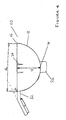
- an acetabular cup 10 which has a part-circular outer surface 12 which is of an appropriate diameter to fit into the acetabulum of a patient.
- the acetabular cup 10 has an outer equatorial edge 16 and defines a pole 14.
- Figures 4 and 5 show the outer surface 12 as having a perfect hemi-spherical shape, advantageously the outer surface 12 may be equatorially expanded.
- the diameter d 1 at the pole 14 corresponds to the diameter of the prepared acetabulum
- the diameter d 2 at the outer equatorial edge 16 may be somewhat greater by perhaps 1 to 3 mm.
- An equatorially expanded outer surface 12 provides the advantage that a press-fit is provided between the acetabular cup 10 and the acetabulum at the mouth of the device and a line-to-line fit at the pole 14. This results in an improved stress distribution to the patient's acetabulum.
- the acetabular cup 10 also has a part circular, typically hemi-spherical or substantially hemispherical, articulating surface 18 having a diameter suitable for receiving a prosthetic or resurfaced femoral head, not shown.
- the acetabular cup 10 is preferably formed of metal, preferably a high carbon cobalt chrome-alloy, although it could be formed of a ceramic material such as zirconia or alumina. Whatever the material, the surface may be modified. It will also be understood that the acetabular cup 10 may be provided with a UHMWPE (Ultra High Molecular Weight Polyethylene) liner if desired, which will then provide the articulating surface in place of the acetabular cup itself.
- UHMWPE Ultra High Molecular Weight Polyethylene
- An annular rim 20 extends between the outer surface 12 and the articulating surface 18.
- the rim 20 is substantially planar and is provided with three angularly spaced recesses 22 to facilitate introduction of the acetabular cup 10 into the acetabulum.
- the recesses 22 open out only into the rim 20 and are spaced from both the outer surface 12 and the articulating surface 18.
- the outer surface 12 may be textured and/or comprise a plurality of splines 24.
- the splines 24 inhibit rotation of the cup 10 with respect to the acetabulum.
- two sets of splines 24 are provided on opposing sides of the acetabular cup 10 at locations spaced from the recesses 22.
- the acetabular cup 10 may further comprise a supero-medial peg 26 which extends radially outwardly from the pole 14 of the outer surface 12 to provide enhanced initial fixation.
- the acetabular cup 10 further comprises a flange 30.
- the flange 30 comprises a first portion 32 which extends radially outwardly from the outer surface 12 and has an upper surface 33 substantially co-planar with the rim 20.
- the flange 30 also comprises a second portion 34 which is inclined with respect to the first portion 32 and extends from an end of the first portion 32 remote from the outer surface 12 in a radially outwardly and downwardly direction with respect to the rim 20.
- the second portion 34 is inclined with respect to the first portion 32 at an angle ⁇ of upto approximately 50°.
- the angle of inclination ( ⁇ ) lies within the range 5° - 25° while more preferably still the angle of inclination ( ⁇ ) lies within the range 10° - 20°.
- the second portion 34 of the flange 30 is sized so as to accommodate a number of countersunk threaded apertures 36 through which fixation members may be received. Although three apertures 36 are shown in Figure 3 , it will be understood that the use of two fixation members may be sufficient to adequately secure the acetabular cup 10 within the acetabulum. In some cases only one fixation member may be required.
- the outer surface 12 of the acetabular cup 10 and the under surface of the flange 30 may be coated with an artificial bone substitute material such as hydroxyapatite (HAP) to provide optimum long term osteo-integration.
- the outer surface 12 may have a porous coated or plasma coated surface to enhance fixation of the acetabular cup 10 within the acetabulum.
- One particularly preferred coating option is a dual coating comprising a plasma sprayed layer of either Cobalt Chromium or Titanium, followed by a layer of hydroxyapatite. The use of such dual coatings combines the enhanced osteo-integration provided by hydroxyapatite and the increased surface area provided by the Cobalt Chromium or Titanium.
- a fixation member 50 is shown in Figure 6 .
- the fixation member 50 comprises an upper portion 52, a lower portion 56 and a central portion 54 interconnecting the upper and lower portions 52 and 56.
- the upper portion 52 has a diameter d 3 and the lower portion 56 a diameter d 4 , where d 3 is greater than d 4 .
- the fixation member 50 is provided with a thread 58, which is shown as being continuous and of constant pitch over the upper, central and lower portions, 52, 54 and 56.
- the thread may be omitted from the central portion 54 and that the same or different thread configurations may be provided on the upper and lower portions 52 and 56 provided that the thread configurations on both portions have the same pitch and provided that the thread configuration on the lower portion 56 starts at a location so as to be a continuation of the same helix defined by the thread configuration on the upper portion 52 albeit of reduced radius.
- the thread configuration on the upper portion 52 may comprise a metric thread, for example a metric 8mm, M8, thread while the thread configuration on the lower portion 56 may be of a corti/cancellous bone thread design. Nonetheless, if desired, the thread configuration on the upper and lower portions 52 and 56 may be of the same cross-sectional shape.
- the thread configuration on the lower portion 56 is preferably of a corti/cancellous bone thread design in order to provide secure attachment to the bone surrounding the acetabulum and the thread configuration on the upper portion 52 may also be of this design.
- the thread configuration on the upper portion 52 is required to threadingly engage the threaded apertures 36 provided in the flange 30.
- these threaded apertures 36 may be provided with a mating corti/cancellous bone thread design.
- the threaded apertures 36 may be provided with a metric thread such as a metric 8mm, M8, thread since a corti/cancellous bone thread will nonetheless threadingly engage a mating metric thread of the same diameter provided that the threads are engineered correctly.
- the fixation member 50 further comprises a frustoconical head 60 having a standard hexagonal drive with which to receive a hexagonal insertion tool.
- a frustoconical head 60 having a standard hexagonal drive with which to receive a hexagonal insertion tool.
- other drive mechanisms may be suitable.
- the fixation member 50 further comprises a tip 70 which is conical in shape and may be fluted to allow self tapping.
- the fixation member 50 may have a length in the range from 10 to 70 mm. Preferably the fixation member may have a length in the range from 20 to 50 mm.
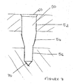
- Figure 7 shows the fixation member 50 when positioned in use, with the thread configuration omitted for clarity.
- the upper portion 52 is engaged in one of the threaded apertures 36 to a depth such that the head of the fixation member 60 is flush with an upper surface of the flange 30.
- the frustroconical side wall of the head 60 engages a correspondingly shaped bevel surrounding the aperture 36 to lock the head 60 into the flange 30 to prevent the fixation member from loosening.
- the lower portion 56 is engaged in the acetabulum while the central portion 54 lies between the flange 30 and the acetabulum.
- central portion 54 has been described as tapering from the diameter of the upper portion 52 to the diameter of the lower portion 56, in an alternative embodiment the central portion may be omitted such that the upper portion 52 is contiguous with the lower portion 56 and the upper and lower portions meet at a step change in the diameter of the fixation member 50.
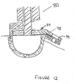
- the introducing tool 80 comprises an elongate stem 82 and a head 84.
- the stem 82 comprises an externally threaded part 86 and a handle 88 pivotally connected to the threaded part 86.
- An internally threaded sleeve 90 is mounted on the threaded part 86 of the stem 82 for a purpose which will become apparent.
- the head 84 comprises a plate 92 having three upstanding lugs 94.
- a generally L-shaped finger 96 is pivotally mounted on each of the lugs 94.
- the free ends of the fingers 96 are moveable radially inwards towards an elongate axis of the stem 82 and into a position in which they are insertable into the recesses 22 in the rim 20 of the acetabular cup 10.
- the threaded sleeve 90 can be rotated to bring one end of the sleeve into contact with the fingers 96. This causes the free ends of the finger 96 to pivot radially outwards and to be urged into frictional engagement with the walls of the recesses 22.
- the surgeon may then use the introducing tool 80 to manipulate the acetabular cup 10.
- the surgeon simply rotates the sleeve 90 in the opposite direction to release the fingers 96 from frictional engagement with the recesses 22.
- the introducing tool 80 may then be removed from the acetabular cup 10.
- the articulating surface 18 of the acetabular cup is not compromised and this helps to minimise the wear between the femoral head and the interior surface of the cup.
- the plate 92 further comprises a flange plate 98 configured to correspond with the flange 30 of the acetabular cup 10.
- the flange plate 98 is inclined to the plate 92 by the same angle and in the same direction as the second portion 34 of the flange 30 is inclined to the first portion 32.
- the flange plate 98 is provided with three guide apertures 99 which are disposed so as to be concentrically aligned with the apertures 36 provided in the flange 30 of the acetabular cup 10 once the acetabular cup is mounted on the introducing tool 80.
- the diameter of the guide apertures 99 is however somewhat larger than that of the apertures 36.
- Figure 10 shows a starter tap 100 comprising an upper portion 102, a lower portion 104 and a tip 108.
- the upper portion 102 has the same diameter d 3 as the upper portion 52 of the fixation member 50 and the lower portion 104 has the same diameter d 4 as the lower portion 56.
- the upper and lower portions 102 and 104 meet at a radially projecting shoulder 106.
- a helical thread 110 is provided on the exterior of the upper portion 102 which is capable of threaded engagement with the apertures 36 provided in flange 30.
- the exterior of the lower portion 104 is provided with a helical cutting edge 112 having the same pitch as thread 110 with which to form an internal thread capable of threaded engagement with the helical thread provided on the lower portion 56 of the fixation member 50.
- the length L 1 of the upper portion 102 is significantly longer than the length L 2 of the lower portion 106.
- the upper portion 102 is adapted to be connected to a handle or similar tool, not shown, in order to facilitate the manipulation of the starter tap 100 and in particular to rotate the starter tap about a longitudinal axis.
- the acetabulum is prepared in the conventional manner by reaming the acetabulum until a preoperatively selected size is achieved. Any osteophytes are removed and soft tissue cleared from the acetabular margin. If required, a bore is made in the acetabulum for receiving the supero medial peg 26.
- the appropriate sized acetabular cup 10 is mounted to the head 84 of the introducing tool 80 in the manner previously described such that flange 98 overlies flange 30 and so that guide apertures 99 are aligned with apertures 36.
- the introducing tool 80 is then used to position the acetabular cup 10 within the acetabulum such that the flange 30 lies on the superior side.
- the acetabular cup 10 may be orientated differently if adequate fixation may be achieved with the flange 30 in a different location.
- the acetabular cup 10 is then firmly impacted into position.
- a small drill guide tube is introduced into one of the guide apertures 99.
- the small drill guide tube projects upwardly from flange 98 and away from the acetabular cup 10 and serves to guide a drill bit for drilling a pilot hole 113 in the bone underlying flange 30. Because the second portion 34 of the flange 30 is inclined with respect to the first portion 32 it is able to overly more closely the bone surrounding the acetabulum with the result that the small drill guide tube (and indeed the tap guide tube referred to subsequently) extends substantially perpendicularly to the bone underlying the flange 30.
- pilot hole 113 may also be formed substantially perpendicularly to the surface of the bone underlying the flange 30 leading to enhanced fixation of the acetabular cup 10.
- guide aperture 99 may be internally threaded to threadingly engage an external thread provided on one end of the small drill guide tube.
- the small drill guide tube is then removed from the guide aperture 99 and a depth gauge, not shown, is used to assess the correct length of the fixation member 50 to be used.
- a tap guide tube 114 similar to the small drill guide tube is then introduced into the guide aperture 99 as shown in Figure 11 .
- the starter tap 100 is introduced into the tap guide tube 114 such that the tip 108 passes first through the guide aperture 99 and then through aperture 36.
- As the starter tap 100 is advanced so it is rotated such that the external helical thread 110 on the upper portion 102 engages with the internal thread 38 of the aperture 36.
- the length L 1 of the upper portion 102 is significantly longer than the length L 2 of the lower portion 106 it can be ensured that this threaded engagement occurs before tip 108 of the starter tap 100 engages the bone. Nonetheless, further rotation of the starter tap 100 causes the tip 108 to be introduced into the previously drilled pilot hole 113.
- the cutting edge 112 provided on the exterior of the lower portion 104 cuts the start of a thread configuration on an interior surface of the previously drilled pilot hole 113.
- the external helical thread 110 on the upper portion 102 engages with the internal thread of the aperture 36 before the cutting edge 112 engages with the pilot hole 113, it is possible to ensure that the thread configuration that is cut in the pilot hole 113 forms a continuation of the same helix defined by the internal thread of the aperture 36 albeit of reduced radius.
- the starter tap 100 is intended to only cut the first few rotations of a thread configuration within the pilot hole 113, the length L 2 of the lower portion is made deliberately short. As a result continued rotation of the starter tap 100 soon brings the radially projecting shoulder 106 into engagement with the bone surrounding the pilot hole 113. The surgeon will feel this and cease further rotation of the starter tap 100. The starter tap 100 is then rotated in the opposite direction to remove the starter tap from the tap guide tube 114.
- a second, full length tap may then be introduced through the tap guide tube 114 and aperture 36 to fully tap the pilot hole 113.
- the use of the tap guide tube 114 provides enhanced accuracy and ensures that the hole is tapped centrally.
- a fixation member 50 is offered up to one of the guide apertures 99 with the introducing tool 80 still in position.
- the tip 70 of the fixation member 50 passes through the guide aperture 99 and the threaded aperture 36 and into the now fully tapped pilot hole 113.
- Rotation of the fixation member 50 by means of the hexagonal drive causes the thread configuration on the lower portion 56 to threadingly engage with the newly cut thread configuration on the interior surface of the pilot hole 113 before the thread configuration on the upper portion 52 threadingly engages the threaded aperture 36. Nonetheless, continued rotation of the fixation member 50 does eventually bring the thread configuration on the upper portion 52 into threaded engagement with the threaded aperture 36.
- the frustroconical head 60 passes through the guide aperture 99 and into engagement with a correspondingly shaped bevel surrounding the threaded aperture 36.
- the head 60 lies flush with an upper surface of the flange 30. Nonetheless, the act of maintaining the introducing tool 80 in position whilst the fixation member 50 is introduced provides stability against rotational movement of the acetabular cup 10 as the fixation member 50 is tightened.
- the process is repeated for a second and subsequent fixation members 50 as required and the stability of the acetabular cup 10 in the acetabulum is then assessed.
- the fixation member, and method preparation of the pilot hole for receiving such a fixation member may also find use in the fixation of other implants in the body, where it is desired, for example, to alleviate the problems caused by the reaction forces generated when inserting screws into bone, or other material.
- the tap guide tube 114 may be externally threaded at one end to threadingly engage an internal thread provided in the guide aperture 99.
- the starter tap 100 has been described as comprising an upper portion 102 and a lower portion 104 that meet at a radially projecting shoulder 106, this need not necessarily be the case.
- the two portions 102 and 104 could merge via a tapered intermediate portion and the surgeon would still feel sufficient resistance when in use for him to know when the first few rotations had been cut in the pilot hole and when to cease further rotation.
Landscapes
- Health & Medical Sciences (AREA)
- Orthopedic Medicine & Surgery (AREA)
- Life Sciences & Earth Sciences (AREA)
- Engineering & Computer Science (AREA)
- Heart & Thoracic Surgery (AREA)
- Veterinary Medicine (AREA)
- Public Health (AREA)
- General Health & Medical Sciences (AREA)
- Animal Behavior & Ethology (AREA)
- Biomedical Technology (AREA)
- Surgery (AREA)
- Oral & Maxillofacial Surgery (AREA)
- Transplantation (AREA)
- Vascular Medicine (AREA)
- Cardiology (AREA)
- Nuclear Medicine, Radiotherapy & Molecular Imaging (AREA)
- Medical Informatics (AREA)
- Molecular Biology (AREA)
- Dentistry (AREA)
- Physical Education & Sports Medicine (AREA)
- Mechanical Engineering (AREA)
- General Engineering & Computer Science (AREA)
- Neurology (AREA)
- Prostheses (AREA)
- Surgical Instruments (AREA)
- Medicines Containing Material From Animals Or Micro-Organisms (AREA)
Claims (14)
- Knochen-Gewindebohrsatz zum Schneiden eines Innengewindes in Knochen, der eine Bohrung definiert, wobei der Satz Folgendes umfasst:eine Führungskomponente, die dafür eingerichtet ist, auf dem Knochen aufzuliegen, und die eine Gewindeöffnung (36) in Ausrichtung mit der Bohrung hat, undeinen Gewindebohrer (100), der einen ersten Abschnitt (102), der einen ersten Durchmesser (d3) hat, und einen zweiten Abschnitt (104), der einen zweiten Durchmesser (d4) hat, umfasst, wobei der zweite Durchmesser (d4) kleiner ist als der erste Durchmesser (d3), wobei der erste Abschnitt (102) ein Außengewinde (110) hat, das dafür eingerichtet ist, die Gewindeöffnung (36) der Führungskomponente in Gewindeeingriff zu nehmen, und der zweite Abschnitt (104) eine spiralförmige Schneidkante (112) hat, die dafür eingerichtet ist, innerhalb der Bohrung aufgenommen zu werden und das Innengewinde zu schneiden, wobei die Führungskomponente und der Gewindebohrer (100) verhältnismäßig derart bemessen sind, dass auf ein Einführen des Gewindebohrers (100) in die Gewindeöffnung (36) mit dem zweiten Abschnitt (104) zu dem Knochen hin der erste Abschnitt (102) des Gewindebohrers (100) die Gewindeöffnung (36) in Gewindeeingriff nimmt, bevor die spiralförmige Schneidkante (112) den Knochen in Eingriff nimmt.
- Satz nach Anspruch 1, wobei die Gewindeöffnung (36) eine Achse definiert und eine axiale Abmessung hat, die größer ist als die axiale Länge (L2) des zweiten Abschnitts (104) des Gewindebohrers (100).
- Satz nach Anspruch 1 oder Anspruch 2, wobei der erste Abschnitt (102) und der zweite Abschnitt (104) zusammenhängend sind und sich an einem Absatz (106) treffen.
- Satz nach Anspruch 1 oder Anspruch 2, wobei der erste und der zweite Abschnitt (102, 104) durch einen Zwischenabschnitt miteinander verbunden sind, wobei sich der Zwischenabschnitt von dem ersten Durchmesser (d3) angrenzend an den ersten Abschnitt (102) bis zu dem zweiten Durchmesser (d4) angrenzend an den zweiten Abschnitt (104) verjüngt.
- Satz nach einem der Ansprüche 1 bis 4, wobei die spiralförmige Schneidkante (112), die an dem zweiten Abschnitt (104) des Gewindebohrers (100) bereitgestellt wird, die gleiche Steigung wie das Außengewinde (110), das an dem ersten Abschnitt (102) des Gewindebohrers (100) bereitgestellt wird, und die gleiche Winkelverschiebung wie eine Fortsetzung der Spirale, die durch das Außengewinde (110) definiert wird, hat.
- Satz nach einem der Ansprüche 1 bis 5, wobei die spiralförmige Schneidkante (112), die an dem zweiten Abschnitt (104) des Gewindebohrers (100) bereitgestellt wird, dafür eingerichtet ist, ein Innengewinde zu schneiden, dass zu einem Gewindeeingriff mit einem Kortikalis-/Spongiosa-Gewinde in der Lage ist.
- Satz nach einem der Ansprüche 1 bis 6, wobei der Gewindebohrer im Wesentlich ist wie hierin unter Bezugnahme auf Figur 3 bis 12 der beigefügten Zeichnungen beschrieben.
- Satz nach einem der Ansprüche 1 bis 7, wobei die Führungskomponente eine prothetische Einrichtung umfasst, die mit Hilfe eines Fixationselements (50), das durch die Gewindeöffnung hindurchgeht, an dem Knochen zu befestigen ist.
- Satz nach Anspruch 8, wobei die prothetische Einrichtung eine Pfanne (10) für eine Verwendung in einem Kugelzapfengelenk umfasst, wobei die Pfanne (10) eine Außenfläche (12), eine innere Gelenkfläche (18) und einen Flansch (30), der sich von der Pfanne (10) aus nach außen und weg von der inneren Gelenkfläche (18) erstreckt, umfasst, wobei die Gewindeöffnung (36) in dem Flansch (30) bereitgestellt wird.
- Satz nach Anspruch 8 oder Anspruch 9, wobei die Einrichtung eine prothetische Pfanne (10) für eine Verwendung in einem Kugelzapfengelenk umfasst, wobei die Pfanne (10) eine Außenfläche (12), eine innere Gelenkfläche (18), einen Rand (20), der sich zwischen der Außenfläche (12) und der inneren Gelenkfläche (18) erstreckt, und einen Flansch (30), der sich von der Pfanne (10) aus nach außen und weg von der inneren Gelenkfläche (18) erstreckt, umfasst, wobei wenigstens ein Abschnitt (34) des Flanschs (30) in Bezug auf eine durch den Rand (20) definierte Ebene geneigt ist und eine Öffnung (36) hat, die dafür eingerichtet ist, ein Fixationselement (50) aufzunehmen.
- Satz nach einem der Ansprüche 8 bis 10 in Kombination mit einem Knochen-/Prothese-Fixationselement (50), das einen ersten Abschnitt (52), der einen ersten Durchmesser (d3) und eine erste Gewindekonfiguration hat, und einen zweiten Abschnitt (56), der einen zweiten Durchmesser (d4) und eine zweite Gewindekonfiguration hat, umfasst, wobei der zweite Durchmesser (d4) kleiner ist als der erste Durchmesser (d3), und die zweite Gewindekonfiguration die gleiche Steigung wie die erste Gewindekonfiguration und die gleiche Winkelverschiebung wie eine Fortsetzung der Spirale, die durch die erste Gewindekonfiguration definiert wird, hat.
- Kombination nach Anspruch 11, wobei sowohl die erste Gewindekonfiguration des Fixationselements (50) als auch das Außengewinde (110), das an dem ersten Abschnitt (102) des Gewindebohrers (100) bereitgestellt wird, dafür eingerichtet sind, die Gewindeöffnung (36) der Führungskomponente in Gewindeeingriff zu nehmen.
- Kombination nach Anspruch 11 oder Anspruch 12, wobei die zweite Gewindekonfiguration des Fixationselements (50) dafür eingerichtet ist, das durch die spiralförmige Schneidkante (112), die an dem zweiten Abschnitt (104) des Gewindebohrers (100) bereitgestellt wird, geschnittene Innengewinde in Gewindeeingriff zu nehmen.
- Kombination nach Anspruch 13, soweit abhängig von Anspruch 12, wobei, nach dem Entfernen des Gewindebohrers (100) aus der Führungskomponente und dem Einführen des Fixationselements (50) in die Gewindeöffnung (36) die zweite Gewindekonfiguration des Fixationselements (50) das durch die spiralförmige Schneidkante (112), die an dem zweiten Abschnitt (104) des Gewindebohrers (100) bereitgestellt wird, geschnittene Innengewinde in Gewindeeingriff nimmt, bevor die erste Gewindekonfiguration des Fixationselements (50) die Gewindeöffnung (36) der Führungskomponente in Gewindeeingriff nimmt.
Applications Claiming Priority (2)
| Application Number | Priority Date | Filing Date | Title |
|---|---|---|---|
| GB0321801A GB2406056B (en) | 2003-09-17 | 2003-09-17 | Prosthetic cup |
| GB0321801 | 2003-09-17 |
Publications (2)
| Publication Number | Publication Date |
|---|---|
| EP1516603A1 EP1516603A1 (de) | 2005-03-23 |
| EP1516603B1 true EP1516603B1 (de) | 2009-09-23 |
Family
ID=29227267
Family Applications (1)
| Application Number | Title | Priority Date | Filing Date |
|---|---|---|---|
| EP04255636A Expired - Lifetime EP1516603B1 (de) | 2003-09-17 | 2004-09-16 | Satz zum Schneiden eines Innengewindes in Knochen |
Country Status (6)
| Country | Link |
|---|---|
| US (1) | US7641656B2 (de) |
| EP (1) | EP1516603B1 (de) |
| AT (1) | ATE443495T1 (de) |
| DE (1) | DE602004023262D1 (de) |
| ES (1) | ES2333867T3 (de) |
| GB (1) | GB2406056B (de) |
Families Citing this family (29)
| Publication number | Priority date | Publication date | Assignee | Title |
|---|---|---|---|---|
| US8123814B2 (en) | 2001-02-23 | 2012-02-28 | Biomet Manufacturing Corp. | Method and appartus for acetabular reconstruction |
| US7597715B2 (en) | 2005-04-21 | 2009-10-06 | Biomet Manufacturing Corp. | Method and apparatus for use of porous implants |
| US7717945B2 (en) | 2002-07-22 | 2010-05-18 | Acumed Llc | Orthopedic systems |
| GB2437441B (en) * | 2003-06-20 | 2008-03-19 | Acumed Llc | Bone plates with intraoperatively tapped apertures |
| AU2004249313B2 (en) | 2003-06-20 | 2009-01-15 | Acumed Llc | Bone plates with intraoperatively tapped apertures |
| US8998919B2 (en) | 2003-06-25 | 2015-04-07 | DePuy Synthes Products, LLC | Assembly tool for modular implants, kit and associated method |
| US7582092B2 (en) | 2003-06-25 | 2009-09-01 | Depuy Products, Inc. | Assembly tool for modular implants and associated method |
| US8266780B2 (en) | 2005-04-21 | 2012-09-18 | Biomet Manufacturing Corp. | Method and apparatus for use of porous implants |
| US8292967B2 (en) | 2005-04-21 | 2012-10-23 | Biomet Manufacturing Corp. | Method and apparatus for use of porous implants |
| US8066778B2 (en) | 2005-04-21 | 2011-11-29 | Biomet Manufacturing Corp. | Porous metal cup with cobalt bearing surface |
| US8021432B2 (en) | 2005-12-05 | 2011-09-20 | Biomet Manufacturing Corp. | Apparatus for use of porous implants |
| US7635447B2 (en) | 2006-02-17 | 2009-12-22 | Biomet Manufacturing Corp. | Method and apparatus for forming porous metal implants |
| US8052687B2 (en) * | 2006-09-29 | 2011-11-08 | Depuy Products, Inc. | Calcar planar |
| US20080109085A1 (en) | 2006-11-03 | 2008-05-08 | Howmedica Osteonics Corp. | Method and apparatus for hip femoral resurfacing tooling |
| US8556912B2 (en) * | 2007-10-30 | 2013-10-15 | DePuy Synthes Products, LLC | Taper disengagement tool |
| US8518050B2 (en) | 2007-10-31 | 2013-08-27 | DePuy Synthes Products, LLC | Modular taper assembly device |
| US8123815B2 (en) | 2008-11-24 | 2012-02-28 | Biomet Manufacturing Corp. | Multiple bearing acetabular prosthesis |
| US8308810B2 (en) | 2009-07-14 | 2012-11-13 | Biomet Manufacturing Corp. | Multiple bearing acetabular prosthesis |
| WO2011035145A1 (en) * | 2009-09-18 | 2011-03-24 | Biomet Manufacturing Corp. | Elbow resurfacing prosthesis |
| US20110218580A1 (en) | 2010-03-08 | 2011-09-08 | Stryker Trauma Sa | Bone fixation system with curved profile threads |
| US8533921B2 (en) | 2010-06-15 | 2013-09-17 | DePuy Synthes Products, LLC | Spiral assembly tool |
| WO2012006444A2 (en) * | 2010-07-09 | 2012-01-12 | The Cleveland Clinic Foundation | Method and apparatus for providing a relative location indication during a surgical procedure |
| US9095452B2 (en) | 2010-09-01 | 2015-08-04 | DePuy Synthes Products, Inc. | Disassembly tool |
| EP2856974B1 (de) | 2011-04-06 | 2017-03-01 | DePuy Synthes Products, LLC | Distale Reibahle |
| CA2838556C (en) | 2011-08-08 | 2016-06-07 | Hip Innovation Technology Llc | Orthopedic instrument, system and method for implanting an acetabular cup |
| US9119722B1 (en) | 2011-08-18 | 2015-09-01 | Sharat Kusuma | Measurement and placement techniques in hip resurfacing and the like |
| US10456262B2 (en) * | 2016-08-02 | 2019-10-29 | Howmedica Osteonics Corp. | Patient-specific implant flanges with bone side porous ridges |
| TWI606813B (zh) * | 2016-12-30 | 2017-12-01 | 財團法人金屬工業研究發展中心 | Multi-piece combined artificial joint cup structure |
| TWI772178B (zh) * | 2021-09-10 | 2022-07-21 | 陳俊龍 | 單次鑽鑿的整套植入組件 |
Family Cites Families (25)
| Publication number | Priority date | Publication date | Assignee | Title |
|---|---|---|---|---|
| GB504095A (en) * | 1938-08-17 | 1939-04-19 | John Wycliffe Leighton | Improved method of cutting screw threads on mechanical parts |
| CH614761A5 (en) * | 1977-03-03 | 1979-12-14 | Alphons Rogger | Screw |
| GB8310675D0 (en) * | 1983-04-20 | 1983-05-25 | Church J C M | Endoprosthetic bone joint devices |
| US4611587A (en) | 1984-09-24 | 1986-09-16 | Powlan Roy Y | Device for cutting threads in the walls of the acetabular cavity in humans |
| GB2177325A (en) * | 1985-07-03 | 1987-01-21 | Keg Services Ltd | Modification of beer barrels |
| FR2634372A1 (fr) * | 1988-07-20 | 1990-01-26 | Balay Bruno | Module de reconstruction cotyloidienne |
| WO1990002526A1 (en) * | 1988-09-09 | 1990-03-22 | Australian Defence Industries Pty. Limited | Screw |
| DE9017101U1 (de) * | 1990-12-19 | 1991-04-11 | Gerhard Hug Gmbh, 7801 Umkirch | Knochenschraube |
| US5423826A (en) * | 1993-02-05 | 1995-06-13 | Danek Medical, Inc. | Anterior cervical plate holder/drill guide and method of use |
| ATE210416T1 (de) * | 1994-06-15 | 2001-12-15 | Sulzer Orthopaedie Ag | Künstliche hüftgelenkpfanne |
| SE506404C2 (sv) * | 1994-11-22 | 1997-12-15 | Lars Johan Henrik Hansson | Styrinstrument avsett för fixering av benfragment vid benbrott |
| US5769856A (en) * | 1996-06-24 | 1998-06-23 | Osteonics Corp. | Drill guide and implant method |
| FR2758255B1 (fr) * | 1997-01-16 | 1999-07-16 | Groupe Lepine | Implant cotyloidien "de reprise" |
| US5865847A (en) | 1997-03-06 | 1999-02-02 | Sulzer Spine-Tech Inc. | Lordotic spinal implant |
| JPH10277052A (ja) * | 1997-04-02 | 1998-10-20 | For S Medical:Kk | 骨接合用スクリュー |
| US6162257A (en) * | 1997-10-31 | 2000-12-19 | Gustilo; Ramon B. | Acetabular cup prosthesis with extension for deficient acetabulum |
| IT1303805B1 (it) * | 1998-12-01 | 2001-02-23 | Bridgehall Consultants Ltd | Cotile da revisione per impiego nel trattamento di patologiedell'anca. |
| US6053916A (en) | 1999-02-17 | 2000-04-25 | Moore; Michael R. | Sacroiliac implant |
| US6355043B1 (en) * | 1999-03-01 | 2002-03-12 | Sulzer Orthopedics Ltd. | Bone screw for anchoring a marrow nail |
| FR2793137B1 (fr) * | 1999-05-07 | 2001-08-31 | Tornier Sa | Implant cotyloidien et son dispositif d'adaptation |
| ATE257674T1 (de) * | 1999-09-13 | 2004-01-15 | Synthes Ag | Knochenplattenvorrichtung |
| FR2798841B1 (fr) * | 1999-09-28 | 2002-03-01 | Depuy France | Implant acetabulaire pour prothese de hanche |
| FR2819172B3 (fr) * | 2001-01-08 | 2003-01-31 | Groupe Lepine | Implant cotyloidien dit "de reprise" |
| SE518461C2 (sv) * | 2001-02-21 | 2002-10-15 | Henrik Hansson | Benskruv, sätt för att framställa dess gängor och borr för att borra hål för detsamma |
| US6875215B2 (en) * | 2002-02-15 | 2005-04-05 | John Stanley Taras | Distraction pin for fracture fixation |
-
2003
- 2003-09-17 GB GB0321801A patent/GB2406056B/en not_active Expired - Lifetime
-
2004
- 2004-09-16 EP EP04255636A patent/EP1516603B1/de not_active Expired - Lifetime
- 2004-09-16 US US10/942,394 patent/US7641656B2/en not_active Expired - Fee Related
- 2004-09-16 DE DE602004023262T patent/DE602004023262D1/de not_active Expired - Lifetime
- 2004-09-16 ES ES04255636T patent/ES2333867T3/es not_active Expired - Lifetime
- 2004-09-16 AT AT04255636T patent/ATE443495T1/de not_active IP Right Cessation
Also Published As
| Publication number | Publication date |
|---|---|
| EP1516603A1 (de) | 2005-03-23 |
| GB2406056A (en) | 2005-03-23 |
| US7641656B2 (en) | 2010-01-05 |
| US20050085820A1 (en) | 2005-04-21 |
| ES2333867T3 (es) | 2010-03-02 |
| DE602004023262D1 (de) | 2009-11-05 |
| GB0321801D0 (en) | 2003-10-15 |
| ATE443495T1 (de) | 2009-10-15 |
| GB2406056B (en) | 2007-07-11 |
Similar Documents
| Publication | Publication Date | Title |
|---|---|---|
| EP1516603B1 (de) | Satz zum Schneiden eines Innengewindes in Knochen | |
| US20240115393A1 (en) | Baseplate of a modular shoulder joint prosthesis and related methods for implanting the same | |
| US11298234B2 (en) | Shoulder arthroplasty system | |
| US10034758B2 (en) | Modular humeral head resurfacing system | |
| US8317871B2 (en) | Modular humeral head resurfacing system | |
| US12582531B2 (en) | Humeral and glenoid articular surface implant systems and methods | |
| US20030125810A1 (en) | Joint replacement prosthesis | |
| US12433755B2 (en) | Articular surface implant systems and methods including glenoid reverse shoulder | |
| EP2268232B1 (de) | Pfannenkomponente einer orthopädischen gelenkprothese | |
| US12127945B2 (en) | Angled baseplate for humeral and glenoid articular surface implant systems and methods | |
| CA2264283A1 (en) | A joint replacement prosthesis | |
| AU6555101A (en) | A joint replacement prosthesis |
Legal Events
| Date | Code | Title | Description |
|---|---|---|---|
| PUAI | Public reference made under article 153(3) epc to a published international application that has entered the european phase |
Free format text: ORIGINAL CODE: 0009012 |
|
| AK | Designated contracting states |
Kind code of ref document: A1 Designated state(s): AT BE BG CH CY CZ DE DK EE ES FI FR GB GR HU IE IT LI LU MC NL PL PT RO SE SI SK TR |
|
| AX | Request for extension of the european patent |
Extension state: AL HR LT LV MK |
|
| 17P | Request for examination filed |
Effective date: 20050905 |
|
| AKX | Designation fees paid |
Designated state(s): AT BE BG CH CY CZ DE DK EE ES FI FR GB GR HU IE IT LI LU MC NL PL PT RO SE SI SK TR |
|
| 17Q | First examination report despatched |
Effective date: 20080425 |
|
| GRAP | Despatch of communication of intention to grant a patent |
Free format text: ORIGINAL CODE: EPIDOSNIGR1 |
|
| GRAS | Grant fee paid |
Free format text: ORIGINAL CODE: EPIDOSNIGR3 |
|
| GRAA | (expected) grant |
Free format text: ORIGINAL CODE: 0009210 |
|
| AK | Designated contracting states |
Kind code of ref document: B1 Designated state(s): AT BE BG CH CY CZ DE DK EE ES FI FR GB GR HU IE IT LI LU MC NL PL PT RO SE SI SK TR |
|
| REG | Reference to a national code |
Ref country code: GB Ref legal event code: FG4D |
|
| REG | Reference to a national code |
Ref country code: CH Ref legal event code: EP |
|
| REG | Reference to a national code |
Ref country code: IE Ref legal event code: FG4D |
|
| REF | Corresponds to: |
Ref document number: 602004023262 Country of ref document: DE Date of ref document: 20091105 Kind code of ref document: P |
|
| PG25 | Lapsed in a contracting state [announced via postgrant information from national office to epo] |
Ref country code: SE Free format text: LAPSE BECAUSE OF FAILURE TO SUBMIT A TRANSLATION OF THE DESCRIPTION OR TO PAY THE FEE WITHIN THE PRESCRIBED TIME-LIMIT Effective date: 20090923 Ref country code: FI Free format text: LAPSE BECAUSE OF FAILURE TO SUBMIT A TRANSLATION OF THE DESCRIPTION OR TO PAY THE FEE WITHIN THE PRESCRIBED TIME-LIMIT Effective date: 20090923 |
|
| PG25 | Lapsed in a contracting state [announced via postgrant information from national office to epo] |
Ref country code: SI Free format text: LAPSE BECAUSE OF FAILURE TO SUBMIT A TRANSLATION OF THE DESCRIPTION OR TO PAY THE FEE WITHIN THE PRESCRIBED TIME-LIMIT Effective date: 20090923 Ref country code: PL Free format text: LAPSE BECAUSE OF FAILURE TO SUBMIT A TRANSLATION OF THE DESCRIPTION OR TO PAY THE FEE WITHIN THE PRESCRIBED TIME-LIMIT Effective date: 20090923 |
|
| NLV1 | Nl: lapsed or annulled due to failure to fulfill the requirements of art. 29p and 29m of the patents act | ||
| REG | Reference to a national code |
Ref country code: ES Ref legal event code: FG2A Ref document number: 2333867 Country of ref document: ES Kind code of ref document: T3 |
|
| PG25 | Lapsed in a contracting state [announced via postgrant information from national office to epo] |
Ref country code: CY Free format text: LAPSE BECAUSE OF FAILURE TO SUBMIT A TRANSLATION OF THE DESCRIPTION OR TO PAY THE FEE WITHIN THE PRESCRIBED TIME-LIMIT Effective date: 20090923 |
|
| PG25 | Lapsed in a contracting state [announced via postgrant information from national office to epo] |
Ref country code: PT Free format text: LAPSE BECAUSE OF FAILURE TO SUBMIT A TRANSLATION OF THE DESCRIPTION OR TO PAY THE FEE WITHIN THE PRESCRIBED TIME-LIMIT Effective date: 20100125 Ref country code: RO Free format text: LAPSE BECAUSE OF FAILURE TO SUBMIT A TRANSLATION OF THE DESCRIPTION OR TO PAY THE FEE WITHIN THE PRESCRIBED TIME-LIMIT Effective date: 20090923 Ref country code: EE Free format text: LAPSE BECAUSE OF FAILURE TO SUBMIT A TRANSLATION OF THE DESCRIPTION OR TO PAY THE FEE WITHIN THE PRESCRIBED TIME-LIMIT Effective date: 20090923 Ref country code: CZ Free format text: LAPSE BECAUSE OF FAILURE TO SUBMIT A TRANSLATION OF THE DESCRIPTION OR TO PAY THE FEE WITHIN THE PRESCRIBED TIME-LIMIT Effective date: 20090923 |
|
| PG25 | Lapsed in a contracting state [announced via postgrant information from national office to epo] |
Ref country code: SK Free format text: LAPSE BECAUSE OF FAILURE TO SUBMIT A TRANSLATION OF THE DESCRIPTION OR TO PAY THE FEE WITHIN THE PRESCRIBED TIME-LIMIT Effective date: 20090923 |
|
| PG25 | Lapsed in a contracting state [announced via postgrant information from national office to epo] |
Ref country code: AT Free format text: LAPSE BECAUSE OF FAILURE TO SUBMIT A TRANSLATION OF THE DESCRIPTION OR TO PAY THE FEE WITHIN THE PRESCRIBED TIME-LIMIT Effective date: 20090923 Ref country code: BE Free format text: LAPSE BECAUSE OF FAILURE TO SUBMIT A TRANSLATION OF THE DESCRIPTION OR TO PAY THE FEE WITHIN THE PRESCRIBED TIME-LIMIT Effective date: 20090923 |
|
| PG25 | Lapsed in a contracting state [announced via postgrant information from national office to epo] |
Ref country code: DK Free format text: LAPSE BECAUSE OF FAILURE TO SUBMIT A TRANSLATION OF THE DESCRIPTION OR TO PAY THE FEE WITHIN THE PRESCRIBED TIME-LIMIT Effective date: 20090923 Ref country code: NL Free format text: LAPSE BECAUSE OF FAILURE TO SUBMIT A TRANSLATION OF THE DESCRIPTION OR TO PAY THE FEE WITHIN THE PRESCRIBED TIME-LIMIT Effective date: 20090923 |
|
| PLBE | No opposition filed within time limit |
Free format text: ORIGINAL CODE: 0009261 |
|
| STAA | Information on the status of an ep patent application or granted ep patent |
Free format text: STATUS: NO OPPOSITION FILED WITHIN TIME LIMIT |
|
| 26N | No opposition filed |
Effective date: 20100624 |
|
| PG25 | Lapsed in a contracting state [announced via postgrant information from national office to epo] |
Ref country code: GR Free format text: LAPSE BECAUSE OF FAILURE TO SUBMIT A TRANSLATION OF THE DESCRIPTION OR TO PAY THE FEE WITHIN THE PRESCRIBED TIME-LIMIT Effective date: 20091224 |
|
| PGFP | Annual fee paid to national office [announced via postgrant information from national office to epo] |
Ref country code: ES Payment date: 20100924 Year of fee payment: 7 |
|
| PGFP | Annual fee paid to national office [announced via postgrant information from national office to epo] |
Ref country code: GB Payment date: 20100913 Year of fee payment: 7 |
|
| PGFP | Annual fee paid to national office [announced via postgrant information from national office to epo] |
Ref country code: DE Payment date: 20100922 Year of fee payment: 7 |
|
| PG25 | Lapsed in a contracting state [announced via postgrant information from national office to epo] |
Ref country code: MC Free format text: LAPSE BECAUSE OF NON-PAYMENT OF DUE FEES Effective date: 20100930 |
|
| REG | Reference to a national code |
Ref country code: CH Ref legal event code: PL |
|
| REG | Reference to a national code |
Ref country code: FR Ref legal event code: ST Effective date: 20110531 |
|
| PG25 | Lapsed in a contracting state [announced via postgrant information from national office to epo] |
Ref country code: IE Free format text: LAPSE BECAUSE OF NON-PAYMENT OF DUE FEES Effective date: 20100916 Ref country code: LI Free format text: LAPSE BECAUSE OF NON-PAYMENT OF DUE FEES Effective date: 20100930 Ref country code: FR Free format text: LAPSE BECAUSE OF NON-PAYMENT OF DUE FEES Effective date: 20100930 Ref country code: CH Free format text: LAPSE BECAUSE OF NON-PAYMENT OF DUE FEES Effective date: 20100930 |
|
| GBPC | Gb: european patent ceased through non-payment of renewal fee |
Effective date: 20110916 |
|
| PG25 | Lapsed in a contracting state [announced via postgrant information from national office to epo] |
Ref country code: IT Free format text: LAPSE BECAUSE OF NON-PAYMENT OF DUE FEES Effective date: 20110916 |
|
| REG | Reference to a national code |
Ref country code: DE Ref legal event code: R119 Ref document number: 602004023262 Country of ref document: DE Effective date: 20120403 |
|
| PG25 | Lapsed in a contracting state [announced via postgrant information from national office to epo] |
Ref country code: DE Free format text: LAPSE BECAUSE OF NON-PAYMENT OF DUE FEES Effective date: 20120403 |
|
| PG25 | Lapsed in a contracting state [announced via postgrant information from national office to epo] |
Ref country code: GB Free format text: LAPSE BECAUSE OF NON-PAYMENT OF DUE FEES Effective date: 20110916 |
|
| PG25 | Lapsed in a contracting state [announced via postgrant information from national office to epo] |
Ref country code: LU Free format text: LAPSE BECAUSE OF NON-PAYMENT OF DUE FEES Effective date: 20100916 Ref country code: HU Free format text: LAPSE BECAUSE OF FAILURE TO SUBMIT A TRANSLATION OF THE DESCRIPTION OR TO PAY THE FEE WITHIN THE PRESCRIBED TIME-LIMIT Effective date: 20100324 Ref country code: BG Free format text: LAPSE BECAUSE OF FAILURE TO SUBMIT A TRANSLATION OF THE DESCRIPTION OR TO PAY THE FEE WITHIN THE PRESCRIBED TIME-LIMIT Effective date: 20090923 |
|
| PG25 | Lapsed in a contracting state [announced via postgrant information from national office to epo] |
Ref country code: TR Free format text: LAPSE BECAUSE OF FAILURE TO SUBMIT A TRANSLATION OF THE DESCRIPTION OR TO PAY THE FEE WITHIN THE PRESCRIBED TIME-LIMIT Effective date: 20090923 |
|
| REG | Reference to a national code |
Ref country code: ES Ref legal event code: FD2A Effective date: 20130417 |
|
| PG25 | Lapsed in a contracting state [announced via postgrant information from national office to epo] |
Ref country code: ES Free format text: LAPSE BECAUSE OF NON-PAYMENT OF DUE FEES Effective date: 20110917 |