EP1516802A2 - Colonne de support pour une ossature de carrosserie - Google Patents
Colonne de support pour une ossature de carrosserie Download PDFInfo
- Publication number
- EP1516802A2 EP1516802A2 EP04021407A EP04021407A EP1516802A2 EP 1516802 A2 EP1516802 A2 EP 1516802A2 EP 04021407 A EP04021407 A EP 04021407A EP 04021407 A EP04021407 A EP 04021407A EP 1516802 A2 EP1516802 A2 EP 1516802A2
- Authority
- EP
- European Patent Office
- Prior art keywords
- hollow profile
- column according
- profile element
- carrying column
- column
- Prior art date
- Legal status (The legal status is an assumption and is not a legal conclusion. Google has not performed a legal analysis and makes no representation as to the accuracy of the status listed.)
- Granted
Links
Images


Classifications
-
- B—PERFORMING OPERATIONS; TRANSPORTING
- B62—LAND VEHICLES FOR TRAVELLING OTHERWISE THAN ON RAILS
- B62D—MOTOR VEHICLES; TRAILERS
- B62D31/00—Superstructures for passenger vehicles
- B62D31/02—Superstructures for passenger vehicles for carrying large numbers of passengers, e.g. omnibus
Definitions
- the invention relates to a support column for a body skeleton of a motor vehicle, in particular sidewall column of a bus, which at opposite ends is connectable with one frame element and the one closed, Has between the two ends extending hollow profile element.
- Body skeleton consisting of a variety of sidewall columns and longitudinal, Transverse, floor and roof beams are constructed, are sufficient in vehicle known and are used especially in bus construction many times.
- An essential Part of a body skeleton represents the sidewall pillar, both for supporting the roof and floor elements as well as for fixing windows and sheet metal plating is provided. So that the sheet metal panels in the upper Part of an Omnis bus and the surface of the trunk flaps a flat surface form, the sidewall column is split. While the upper part of the Side wall pillar in the body rib the connection between the roof racks and represents the longitudinal profile, the lower part of the sidewall column runs easily offset to the rear from the longitudinal profile to the floor beams. In addition, it is in the area formed by the upper and lower side wall pillar and the longitudinal profile Node usually provides a console as an overlay for the floor serves.
- the unit of sidewall columns, roof and floor or floor elements supporting cross members form a so-called annular frame, which while driving Vibration loads and bending stresses, especially in an accident, can be exposed.
- body rungs For example, at the junction sidewall pillar / longitudinal profile / floor support special fittings provided, which strengthen the side wall locally or in shape be mounted by angular elements between adjacent support.
- Such a node reinforcement for skeleton structures of commercial vehicles is For example, from DE 199 29 219 A1 known. When proposed in this document Solution be at the openings of a skeleton, for example. For a door or a Windows, reinforcements on the side walls of the perpendicular to each other Frame carrier welded. By this additional connection adjacent Frame support reinforces the rigidity of the skeleton structure. The attachment takes place here by Anyaken or welding.
- a disadvantage of the described System is that a significant number of node gains is needed and In addition, the production of the required welds very time consuming is.
- the invention is therefore the task based on specifying a support column for a bodywork skeleton of a motor vehicle, the security requirements, especially in relation to the inside the passenger compartment required survival space, and at the same time cost-effective and produce with relatively little manufacturing effort is.
- the support column should be designed as space-saving, so that the space available for use is not restricted.
- the object of the invention is based with a side wall according to of claim 1.
- Advantageous developments of the inventive concept are the subject of the dependent claims and from the following description text and refer to the embodiments.
- the invention relates to a support column for a body skeleton of a motor vehicle, in particular a bus, which at opposite ends, in each case at least A body element is connectable and one between the two Having end extending hollow profile element, which is characterized in that the hollow profile element is made in one piece and has a longitudinal center axis, which is curved or has at least two non-parallel sections, and that connect to the opposite ends of outer column sections, between which a central column section is provided which in at least one Stress direction over a larger moment of resistance to bending than the outer column sections has.
- the effective cross-section of the column in this area is increased and / or the Material properties improved accordingly.
- the sectional use a material of higher quality and / or the selection of one over the outer sheulensbroughen greater wall thickness of the hollow profile element in the middle Column section.
- a material of higher quality in the middle Column section it is of course also conceivable that for the hollow profile element material provided in this area in such a way that this over improved material properties.
- the invention thus becomes firstly a support column for a body skeleton of a Motor vehicle realized, which can be used in areas due to the special shape is, in which the space is cramped.
- a simple production and installation or attachment the column in a body skeleton safe without sacrificing in terms of strength and rigidity must be accepted.
- a carrier element is available placed, which also at connection nodes, for example.
- On a side member of a bus body skeleton It does not have to be shared, but because of its form in one piece can be guided past the carrier.
- the inventive allows Solution the flexible use of high-strength columns at various points of a Body treads also taking into account special design requirements.
- the extending between the ends of the support column in the longitudinal direction hollow profile element is made in one piece.
- This means that it is in the hollow profile element is either a component or that the hollow profile element still before Installation in a bodywork skeleton of several components, for example by welding, has been assembled into a one-piece component.
- the support column at the moment of installation in a body skeleton as a component is available, so that the corresponding column simply in the skeleton can be used and connected to the corresponding body elements is.
- the support column is at opposite ends with body elements, such as to connect about a floor and a roof rack. This concludes, however not sufficient that the support column is connected to other body elements. So It is conceivable that in the middle column area brackets as brackets of a septturas be attached or at least partially a Planking is attached to the support column.
- the support column is mentally divided into three sections subdividable, of which the outer column sections preferably at least in each case partially lie in parallel to each other arranged levels.
- the middle column section is formed in such a column such that this section the Represents connecting element between the two outer column sections.
- the middle column section has two ends, each with the outer Column sections are connected and thus touch at least one level, in the outer column sections, or at least the central column section facing end portions of the outer column sections, are arranged.
- the hollow profile element of the support column according to the invention preferably has an at least approximately rectangular, in particular 60 ⁇ 40 mm 2, large cross section. But it is also conceivable that the cross section has another polygonal or even round contour.
- a further particular embodiment provides a hollow profile element with a square cross section with preferred dimensions of 40 ⁇ 40, 50 ⁇ 50 or 80 ⁇ 80 mm 2 .
- the material is the use of a high-strength steel with a minimum yield strength of 420 N / mm 2 , preferably from
- the support column according to the invention has the hollow profile element in the region of the central column section at least partly over a greater wall thickness than in the area of the outer column sections.
- the wall thickness of the hollow profile is reinforced in this case, the middle column section of the support column according to the invention in at least one possible Stress direction a greater resistance to bending than having the outer pillar portions.
- at least one additional reinforcing element provide that outside, such as a cuff, or within the Hollow profile is arranged such that at least partially a contact surface between hollow profile and reinforcing element is formed.
- the reinforcing element nested several times, so by several Hollow profiles over or put into each other, run.
- the hollow profile and the at least one reinforcing element make an intimate connection in the area of the contact surface.
- connection techniques suitable.
- both manufacturing processes such as soldering, gluing, welding or Rivets are used, which require an excipient for the preparation of the compound, as well as processes such as bending, pressing or shrinking or shrinking, with which a positive connection between the hollow profile and the reinforcing element is produced.
- the support column according to the invention the reinforcing element by means of Punch welds connected to the hollow profile element.
- the moment of resistance to bending in the middle column section compared to the outer column sections At least partially increase, it is of course also conceivable in the middle Column section to provide a reinforcing element and a hollow profile with approximately constant wall thickness to choose.
- the connection techniques already described can be used.
- the reinforcing element is arranged in the central column section within the hollow profile element and a hollow profile, in particular with a rectangular or even square cross-section is formed.
- a different, polygonal or round cross section for the hollow profile-like reinforcing element is also possible.
- an alternative embodiment of the support column according to the invention provides to form the reinforcing element in the form of a T, double T, I, U or L profile.
- the reinforcing element preferably comprises at least partially a high-strength steel with a minimum yield strength of 420 N / mm 2 , in particular S 460, on.
- Support column is a very precise adjustment of the resistance torque against Bending by the arrangement of a plurality or a combination of different Achieved elements of the reinforcing elements already described in a support column.
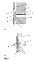
- FIGS. 1 a) and 2 a side views or in FIGS. 1 b) and 2 b) are shown.
- three-dimensional representations of a support column designed according to the invention see, which are known from that shown in Figure 3 and from the prior art In particular, distinguish support pillar in that they despite an S-stroke have within the support column a continuous hollow profile, the in In this case, from a floor to a roof rack ranges.
- Same component components are provided in the figures with the same reference numerals.
- FIG. 1 shows a part of a coach body skeleton in which an invention executed support column 1 is provided, which has the function of a side wall pillar takes over.
- the side wall pillar 1 provides as an outer boundary of a Bus body skeleton a structural element essential for the statics of the body is because at one end a roof rack and at the opposite end a Shelf supports are attached (not shown).
- Bleckbeplankungen 5 and discs (not shown) with Help appropriate fasteners attached.
- divided sidewall column 1 is shown in Figure 1 sidewall column made in one piece and has a return in the middle region in the form of a s-beat.
- a reinforcing element 3 is provided.
- the reinforcing element 3 is executed hollow profile-like, disposed within the hollow profile element 2 and is in at the top and in the lower area via two holes welded joints 13 with connected to the hollow profile element 2.
- a longitudinal member 6 which ensures the rigidity of a Omnibusberippes longitudinally provides.
- a cross member 7 attached, which serves as a console for the floor 8 of the passenger area 9.
- the passenger area 9 also demarcate against the body skeleton an inner lining 12 is provided, which also on the side wall pillar 1 is fixed and ensures a clean completion of the passenger area 9.
- FIG. 2 shows the same section of a bus body skeleton as in FIG. 1 shown in the region of the transition between passenger area 9 and trunk 10.
- the construction of the body skeleton with the straps, the floor, the trunk lid and the Blechbeklankungen corresponds to that in Figure 1.
- this special Embodiment of the support column according to the invention it is possible with the column to provide a return executed in the form of an S-hit, so that at the sidewall of a bus a one-piece sidewall column 1 is arranged without any loss of security, comfort or convenience Exterior comes.
- FIGS Figure 3 shows two sidewall pillar variants of an omnibus, as shown known in the art.
- Essential feature of the sidewall columns in Figure 3a and 3b is the two-part design.
- the side wall pillar 1 in an upper and a lower pillar component divided to a flat surface to get from the sheet metal 5 and the surface of the Kofferarumklappe 4.
- the support column shown in Figure 3b has next to the upper and lower Column component 1 a, 1 b via an additional reinforcing element 3 that on the Sidewall column, for example, in the event of an accident, should absorb attacking forces.
- This additional component must firstly with the lower pillar component 1b and on the other must during the manufacture of a bus body skeleton a welded joint between the reinforcing element and the upper pillar component 1a.
- the production However, such a weld is very expensive, since the seam in the case of stress located in the area of the highest bending stress.
- FIG. 4 shows the behavior of a ring frame of a bus body skeleton a load case, such as when overturning a bus at a Accident can occur.
- the trunk 10 In the lower area is the trunk 10, the one Variety of trunk struts 11 has to stiffen the skeleton.
- Above of the trunk 10 is a cross member 7, on which later the floor of the Passenger area is attached.
- the sidewall columns 1 are at the top Ends again connected to each other via a roof rack 15.
- the so-called survival space 14 is shown inside the passenger area 9.
- the dimensions of the survival space 14 are from the legislator prescribed and intended to specify a space in which even in an accident do not penetrate any objects. If now the ring frame shown in Figure 4 with the force F, for example, by tipping over of the bus, applied, shifts the Ringspant in the manner shown. Along the sidewall columns 1, bending stresses occur without providing appropriate protective measures in the area of the attachment point of the cross member 7 have their maximum, so that in Load case the side wall pillar 1 bent in this area and in the Kochlegebsraum 1 would arrive.
Landscapes
- Engineering & Computer Science (AREA)
- Chemical & Material Sciences (AREA)
- Combustion & Propulsion (AREA)
- Transportation (AREA)
- Mechanical Engineering (AREA)
- Body Structure For Vehicles (AREA)
- Rod-Shaped Construction Members (AREA)
Priority Applications (1)
| Application Number | Priority Date | Filing Date | Title |
|---|---|---|---|
| PL04021407T PL1516802T5 (pl) | 2003-09-17 | 2004-09-09 | Słupek ściany bocznej autobusu |
Applications Claiming Priority (2)
| Application Number | Priority Date | Filing Date | Title |
|---|---|---|---|
| DE10342842.9A DE10342842B4 (de) | 2003-09-17 | 2003-09-17 | Tragsäule für ein Karosseriegerippe |
| DE10342842 | 2003-09-17 |
Publications (4)
| Publication Number | Publication Date |
|---|---|
| EP1516802A2 true EP1516802A2 (fr) | 2005-03-23 |
| EP1516802A3 EP1516802A3 (fr) | 2006-05-31 |
| EP1516802B1 EP1516802B1 (fr) | 2008-12-31 |
| EP1516802B2 EP1516802B2 (fr) | 2013-04-10 |
Family
ID=34177785
Family Applications (1)
| Application Number | Title | Priority Date | Filing Date |
|---|---|---|---|
| EP04021407.4A Expired - Lifetime EP1516802B2 (fr) | 2003-09-17 | 2004-09-09 | Colonne de paroi latéral d'un autobus |
Country Status (5)
| Country | Link |
|---|---|
| EP (1) | EP1516802B2 (fr) |
| CN (1) | CN100457530C (fr) |
| DE (2) | DE10342842B4 (fr) |
| ES (1) | ES2316906T5 (fr) |
| PL (1) | PL1516802T5 (fr) |
Families Citing this family (1)
| Publication number | Priority date | Publication date | Assignee | Title |
|---|---|---|---|---|
| EP4721891A1 (fr) | 2024-10-01 | 2026-04-08 | voestalpine Krems GmbH | Véhicule avec cabine, cette cabine munie d'un profilé et ce profilé |
Family Cites Families (14)
| Publication number | Priority date | Publication date | Assignee | Title |
|---|---|---|---|---|
| DE59501217D1 (de) * | 1995-03-22 | 1998-02-12 | Porsche Ag | Hohlprofil für eine Trägerstruktur eines Kraftfahrzeuges |
| DE19519353A1 (de) | 1995-05-26 | 1996-11-28 | Porsche Ag | Träger einer Aufbaustruktur eines Fahrzeuges und Verfahren zu dessen Herstellung |
| DE19638904A1 (de) | 1996-09-23 | 1998-03-26 | Bayerische Motoren Werke Ag | Verfahren zur Herstellung eines Hohlträgers für Fahrzeugkarosserien |
| DE19644047A1 (de) * | 1996-10-31 | 1998-05-07 | Bayerische Motoren Werke Ag | Seitliche Säule für einen Fahrzeug-Karrosseriekörper |
| DE19818260B4 (de) * | 1998-04-23 | 2008-08-21 | Volkswagen Ag | Karosseriesäule, insbesondere B-Säule, für ein Kraftfahrzeug |
| DE19829832B4 (de) * | 1998-07-03 | 2008-03-27 | Volkswagen Ag | Karosseriestruktur für ein Kraftfahrzeug |
| DE19903724A1 (de) * | 1999-01-30 | 2000-08-03 | Porsche Ag | Gerippe für einen Großraumwagen, insbesondere einen Omnibus |
| DE19903722A1 (de) * | 1999-01-30 | 2000-08-03 | Porsche Ag | Wagenkastenseitenwand für Großraumfahrzeuge, insbesondere Omnibusse |
| DE19929219B4 (de) | 1999-06-25 | 2009-02-26 | Man Nutzfahrzeuge Ag | Knotenverstärkung für Gerippestrukturen in Aufbauten von Nutzfahrzeugen |
| EP1227968B1 (fr) * | 1999-10-28 | 2004-01-14 | Toyota Jidosha Kabushiki Kaisha | Structure de montant pour vehicule |
| DE10002617A1 (de) * | 2000-01-22 | 2001-07-26 | Volkswagen Ag | Karosserieelement mit Verstärkungsblech |
| DE10015325A1 (de) * | 2000-03-28 | 2001-10-04 | Volkswagen Ag | Karosseriebauteil aus Stahl |
| DE10126183A1 (de) | 2001-05-30 | 2002-12-12 | Karmann Gmbh W | Einrichtung zum Erhöhen der Festigkeit eines Hohlformteiles einer Fahrzeugkarosserie |
| DE10232320A1 (de) | 2002-07-17 | 2004-02-05 | Bayerische Motoren Werke Ag | Fahrzeugkarosserie mit einer B-Säule |
-
2003
- 2003-09-17 DE DE10342842.9A patent/DE10342842B4/de not_active Expired - Lifetime
-
2004
- 2004-09-09 DE DE502004008762T patent/DE502004008762D1/de not_active Expired - Lifetime
- 2004-09-09 PL PL04021407T patent/PL1516802T5/pl unknown
- 2004-09-09 ES ES04021407T patent/ES2316906T5/es not_active Expired - Lifetime
- 2004-09-09 EP EP04021407.4A patent/EP1516802B2/fr not_active Expired - Lifetime
- 2004-09-17 CN CNB2004100471612A patent/CN100457530C/zh not_active Expired - Lifetime
Also Published As
| Publication number | Publication date |
|---|---|
| EP1516802B1 (fr) | 2008-12-31 |
| ES2316906T3 (es) | 2009-04-16 |
| CN1640747A (zh) | 2005-07-20 |
| ES2316906T5 (es) | 2013-06-04 |
| EP1516802A3 (fr) | 2006-05-31 |
| EP1516802B2 (fr) | 2013-04-10 |
| PL1516802T3 (pl) | 2009-06-30 |
| DE502004008762D1 (de) | 2009-02-12 |
| CN100457530C (zh) | 2009-02-04 |
| PL1516802T5 (pl) | 2013-11-29 |
| DE10342842A1 (de) | 2005-04-28 |
| DE10342842B4 (de) | 2018-04-19 |
Similar Documents
| Publication | Publication Date | Title |
|---|---|---|
| DE10108287B4 (de) | Karosseriestruktur | |
| DE10040824B4 (de) | Lenksäulen-Tragbalkenstruktur | |
| DE4208700C2 (de) | Vorbaukonstruktion für Fahrzeuge | |
| EP0760329B1 (fr) | Ensemble de panneaux latéraux d'une carosserie automobile | |
| DE69708009T2 (de) | Fahrzeugkarosserie | |
| EP1840003B1 (fr) | Elément de renforcement d'un soubassement de porte de carrosserie de véhicule automobile | |
| DE10232841A1 (de) | Bodenträgeranordnung an Kraftfahrzeugen | |
| DE102007030929B9 (de) | Achsträger für Kraftfahrzeuge | |
| DE10028716B4 (de) | Karosserieseitenteilkonstruktion für ein Automobil | |
| DE102013215793A1 (de) | Fahrzeugkarosserie | |
| EP2390164B1 (fr) | Caisse de carrosserie de véhicule dans la zone talon d'une tôle de cabine passagers | |
| DE102016209186B3 (de) | Karosseriestruktur für ein Kraftfahrzeug | |
| DE102009004886B4 (de) | Aufbaustruktur | |
| DE102010051783A1 (de) | Karosserie für einen Kraftwagen | |
| DE102009041315A1 (de) | A-Säule für einen Kraftwagen | |
| EP0896919A2 (fr) | Traverse de support pour une colonne de direction dans un véhicule automobile, notamment dans une voiture | |
| DE102010021137A1 (de) | Karosseriebauteil | |
| DE102005011834B4 (de) | Seitlicher Dachrahmen für ein Kraftfahrzeug | |
| DE102019217259B4 (de) | Kraftfahrzeugkarosserie und Schwellerbaugruppe | |
| DE102013019591A1 (de) | Kopplungsaufbau zur Kopplung eines Dachabschnitts mit Seitenabschnitten eines Fahrzeugs | |
| DE102005045781B4 (de) | Rahmenstruktur | |
| EP1692035B1 (fr) | Montant de porte pour structure de chassis | |
| DE102013000637B4 (de) | Karosseriestruktur für ein Fahrzeug | |
| EP1516802B1 (fr) | Colonne de paroi latéral d'un autobus | |
| DE19538456A1 (de) | Bodengruppe für ein Kraftfahrzeug |
Legal Events
| Date | Code | Title | Description |
|---|---|---|---|
| PUAI | Public reference made under article 153(3) epc to a published international application that has entered the european phase |
Free format text: ORIGINAL CODE: 0009012 |
|
| AK | Designated contracting states |
Kind code of ref document: A2 Designated state(s): AT BE BG CH CY CZ DE DK EE ES FI FR GB GR HU IE IT LI LU MC NL PL PT RO SE SI SK TR |
|
| AX | Request for extension of the european patent |
Extension state: AL HR LT LV MK |
|
| PUAL | Search report despatched |
Free format text: ORIGINAL CODE: 0009013 |
|
| AK | Designated contracting states |
Kind code of ref document: A3 Designated state(s): AT BE BG CH CY CZ DE DK EE ES FI FR GB GR HU IE IT LI LU MC NL PL PT RO SE SI SK TR |
|
| AX | Request for extension of the european patent |
Extension state: AL HR LT LV MK |
|
| 17P | Request for examination filed |
Effective date: 20061125 |
|
| AKX | Designation fees paid |
Designated state(s): AT BE BG CH CY CZ LI |
|
| 17Q | First examination report despatched |
Effective date: 20070202 |
|
| RBV | Designated contracting states (corrected) |
Designated state(s): DE ES FR IT PL SE TR |
|
| REG | Reference to a national code |
Ref country code: DE Ref legal event code: 8566 |
|
| GRAP | Despatch of communication of intention to grant a patent |
Free format text: ORIGINAL CODE: EPIDOSNIGR1 |
|
| RTI1 | Title (correction) |
Free format text: SIDE WALL PILLAR OF A BUS |
|
| GRAS | Grant fee paid |
Free format text: ORIGINAL CODE: EPIDOSNIGR3 |
|
| GRAA | (expected) grant |
Free format text: ORIGINAL CODE: 0009210 |
|
| AK | Designated contracting states |
Kind code of ref document: B1 Designated state(s): DE ES FR IT PL SE TR |
|
| REF | Corresponds to: |
Ref document number: 502004008762 Country of ref document: DE Date of ref document: 20090212 Kind code of ref document: P |
|
| REG | Reference to a national code |
Ref country code: SE Ref legal event code: TRGR |
|
| REG | Reference to a national code |
Ref country code: ES Ref legal event code: FG2A Ref document number: 2316906 Country of ref document: ES Kind code of ref document: T3 |
|
| REG | Reference to a national code |
Ref country code: PL Ref legal event code: T3 |
|
| PLBI | Opposition filed |
Free format text: ORIGINAL CODE: 0009260 |
|
| PLAZ | Examination of admissibility of opposition: despatch of communication + time limit |
Free format text: ORIGINAL CODE: EPIDOSNOPE2 |
|
| 26 | Opposition filed |
Opponent name: DAIMLER AG Effective date: 20090930 |
|
| PLBA | Examination of admissibility of opposition: reply received |
Free format text: ORIGINAL CODE: EPIDOSNOPE4 |
|
| PLAX | Notice of opposition and request to file observation + time limit sent |
Free format text: ORIGINAL CODE: EPIDOSNOBS2 |
|
| PLBB | Reply of patent proprietor to notice(s) of opposition received |
Free format text: ORIGINAL CODE: EPIDOSNOBS3 |
|
| PLAY | Examination report in opposition despatched + time limit |
Free format text: ORIGINAL CODE: EPIDOSNORE2 |
|
| PLBC | Reply to examination report in opposition received |
Free format text: ORIGINAL CODE: EPIDOSNORE3 |
|
| REG | Reference to a national code |
Ref country code: FR Ref legal event code: CD |
|
| REG | Reference to a national code |
Ref country code: ES Ref legal event code: PC2A Owner name: "MAN TRUCK & Effective date: 20110620 Ref country code: ES Ref legal event code: PC2A Owner name: MAN TRUCK & BUS AG Effective date: 20110620 |
|
| REG | Reference to a national code |
Ref country code: DE Ref legal event code: R081 Ref document number: 502004008762 Country of ref document: DE Owner name: MAN TRUCK & BUS AG, DE Free format text: FORMER OWNER: MAN NUTZFAHRZEUGE AG, 80995 MUENCHEN, DE Effective date: 20110518 |
|
| PUAH | Patent maintained in amended form |
Free format text: ORIGINAL CODE: 0009272 |
|
| STAA | Information on the status of an ep patent application or granted ep patent |
Free format text: STATUS: PATENT MAINTAINED AS AMENDED |
|
| 27A | Patent maintained in amended form |
Effective date: 20130410 |
|
| AK | Designated contracting states |
Kind code of ref document: B2 Designated state(s): DE ES FR IT PL SE TR |
|
| REG | Reference to a national code |
Ref country code: SE Ref legal event code: RPEO |
|
| REG | Reference to a national code |
Ref country code: DE Ref legal event code: R102 Ref document number: 502004008762 Country of ref document: DE Effective date: 20130410 |
|
| REG | Reference to a national code |
Ref country code: ES Ref legal event code: DC2A Ref document number: 2316906 Country of ref document: ES Kind code of ref document: T5 Effective date: 20130604 |
|
| REG | Reference to a national code |
Ref country code: PL Ref legal event code: T5 |
|
| REG | Reference to a national code |
Ref country code: FR Ref legal event code: PLFP Year of fee payment: 13 |
|
| REG | Reference to a national code |
Ref country code: FR Ref legal event code: PLFP Year of fee payment: 14 |
|
| REG | Reference to a national code |
Ref country code: FR Ref legal event code: PLFP Year of fee payment: 15 |
|
| REG | Reference to a national code |
Ref country code: DE Ref legal event code: R081 Ref document number: 502004008762 Country of ref document: DE Owner name: MAN TRUCK & BUS SE, DE Free format text: FORMER OWNER: MAN TRUCK & BUS AG, 80995 MUENCHEN, DE |
|
| PGFP | Annual fee paid to national office [announced via postgrant information from national office to epo] |
Ref country code: TR Payment date: 20230828 Year of fee payment: 20 Ref country code: IT Payment date: 20230920 Year of fee payment: 20 |
|
| PGFP | Annual fee paid to national office [announced via postgrant information from national office to epo] |
Ref country code: SE Payment date: 20230926 Year of fee payment: 20 Ref country code: PL Payment date: 20230830 Year of fee payment: 20 Ref country code: FR Payment date: 20230926 Year of fee payment: 20 Ref country code: DE Payment date: 20230928 Year of fee payment: 20 |
|
| PGFP | Annual fee paid to national office [announced via postgrant information from national office to epo] |
Ref country code: ES Payment date: 20231017 Year of fee payment: 20 |
|
| REG | Reference to a national code |
Ref country code: DE Ref legal event code: R071 Ref document number: 502004008762 Country of ref document: DE |
|
| REG | Reference to a national code |
Ref country code: ES Ref legal event code: FD2A Effective date: 20240927 |
|
| PG25 | Lapsed in a contracting state [announced via postgrant information from national office to epo] |
Ref country code: ES Free format text: LAPSE BECAUSE OF EXPIRATION OF PROTECTION Effective date: 20240910 |
|
| REG | Reference to a national code |
Ref country code: SE Ref legal event code: EUG |
|
| PG25 | Lapsed in a contracting state [announced via postgrant information from national office to epo] |
Ref country code: ES Free format text: LAPSE BECAUSE OF EXPIRATION OF PROTECTION Effective date: 20240910 |