EP1516965B1 - Dispositif de balayage pour une balayeuse - Google Patents
Dispositif de balayage pour une balayeuse Download PDFInfo
- Publication number
- EP1516965B1 EP1516965B1 EP04020961A EP04020961A EP1516965B1 EP 1516965 B1 EP1516965 B1 EP 1516965B1 EP 04020961 A EP04020961 A EP 04020961A EP 04020961 A EP04020961 A EP 04020961A EP 1516965 B1 EP1516965 B1 EP 1516965B1
- Authority
- EP
- European Patent Office
- Prior art keywords
- sweeping device
- support frame
- sweeping
- guide tube
- rod
- Prior art date
- Legal status (The legal status is an assumption and is not a legal conclusion. Google has not performed a legal analysis and makes no representation as to the accuracy of the status listed.)
- Expired - Lifetime
Links
- 238000010408 sweeping Methods 0.000 title claims description 186
- 230000008878 coupling Effects 0.000 claims description 31
- 238000010168 coupling process Methods 0.000 claims description 31
- 238000005859 coupling reaction Methods 0.000 claims description 31
- 230000009471 action Effects 0.000 claims description 3
- 230000001360 synchronised effect Effects 0.000 claims description 2
- 230000000717 retained effect Effects 0.000 claims 2
- 241001417527 Pempheridae Species 0.000 abstract description 35
- 244000007853 Sarothamnus scoparius Species 0.000 description 12
- 230000000712 assembly Effects 0.000 description 7
- 238000000429 assembly Methods 0.000 description 7
- 238000004140 cleaning Methods 0.000 description 7
- 230000008901 benefit Effects 0.000 description 4
- 230000008859 change Effects 0.000 description 3
- 238000000034 method Methods 0.000 description 3
- 238000010521 absorption reaction Methods 0.000 description 2
- 230000002401 inhibitory effect Effects 0.000 description 2
- 230000003993 interaction Effects 0.000 description 2
- 230000008569 process Effects 0.000 description 2
- 230000000284 resting effect Effects 0.000 description 2
- 241001136792 Alle Species 0.000 description 1
- 241000365112 Monsonia angustifolia Species 0.000 description 1
- 230000005540 biological transmission Effects 0.000 description 1
- 238000010276 construction Methods 0.000 description 1
- 230000006378 damage Effects 0.000 description 1
- 230000000994 depressogenic effect Effects 0.000 description 1
- 230000001747 exhibiting effect Effects 0.000 description 1
- 238000011010 flushing procedure Methods 0.000 description 1
- 238000009434 installation Methods 0.000 description 1
- 238000004519 manufacturing process Methods 0.000 description 1
- 230000002688 persistence Effects 0.000 description 1
- 230000002829 reductive effect Effects 0.000 description 1
- 230000000452 restraining effect Effects 0.000 description 1
- 230000000630 rising effect Effects 0.000 description 1
- 238000000926 separation method Methods 0.000 description 1
- 230000007480 spreading Effects 0.000 description 1
- 238000003892 spreading Methods 0.000 description 1
- 239000004575 stone Substances 0.000 description 1
- 238000003860 storage Methods 0.000 description 1
- 239000000725 suspension Substances 0.000 description 1
- 230000001052 transient effect Effects 0.000 description 1
- 230000007704 transition Effects 0.000 description 1
- 238000005406 washing Methods 0.000 description 1
Images


Classifications
-
- E—FIXED CONSTRUCTIONS
- E01—CONSTRUCTION OF ROADS, RAILWAYS, OR BRIDGES
- E01H—STREET CLEANING; CLEANING OF PERMANENT WAYS; CLEANING BEACHES; DISPERSING OR PREVENTING FOG IN GENERAL CLEANING STREET OR RAILWAY FURNITURE OR TUNNEL WALLS
- E01H1/00—Removing undesirable matter from roads or like surfaces, with or without moistening of the surface
- E01H1/08—Pneumatically dislodging or taking-up undesirable matter or small objects; Drying by heat only or by streams of gas; Cleaning by projecting abrasive particles
- E01H1/0827—Dislodging by suction; Mechanical dislodging-cleaning apparatus with independent or dependent exhaust, e.g. dislodging-sweeping machines with independent suction nozzles ; Mechanical loosening devices working under vacuum
- E01H1/0836—Apparatus dislodging all of the dirt by suction ; Suction nozzles
- E01H1/0845—Apparatus dislodging all of the dirt by suction ; Suction nozzles with mechanical loosening or feeding instruments for the dirt to be sucked- up, e.g. brushes, scrapers
Definitions
- the invention relates to a sweeping device for a pneumatically-receiving sweeper with a mounted in a support frame sweeping roller, which are associated with suction shafts on both sides and in operative contact with the sweeping roller largely transverse to the longitudinal center axis, wherein the suction shafts are to be brought either with disc brush in combination.
- the roller is arranged behind the suction chute and has the advantage that the impulse of the cleaning work by the roller in its counter-rotating movement moves the dirt in the direction of the suction chute and can be absorbed by it.
- This technique requires that when sweeping with the suction shaft pivoted out of the contour of the vehicle, the latter comes into the direct field of vision of the driver and the roller must be carried in tight tolerances.
- the DR PS 516 072 discloses a sweeper with transversely to the direction of the sweeping vehicle slidably and pivotally sweeping roller, which is not placed with suction wells in an operative connection and arranged in advance on the front of the vehicle.
- the DR PS 617 991 presents a sweeping or washing roller on a sweeper, which is rotatable by means of sliding linkage on a vertical center axis under the vehicle in a horizontal plane.
- the sweeper works without means for receiving the refuse from the road surface and can be due to the inclination of the sweeping roller to the side transport rubbish as a strip for a separate disposal.
- the DR PS 654 239 shows a sweeping device, the resilient selectively arranged sweeping units, such as a sweeping roller or a plate broom, brings out of the periphery of the vehicle spring and the areas of the road edges, preferably the x-el between curb and road surface cleans.
- the sweeping units are attached to resilient arms, which form a movable, storkbill-like parallelogram with the axis of rotation and the shaft of the drive.
- the scripture shows DE 1 774 842 U a self-picking sweeper for the gutter cleaning.
- a roller brush which has a smaller width than that of the sweeping vehicle, is arranged below the vehicle, inclined transversely to its longitudinal center axis.
- a plate broom in the area of the on-board board and a separate suction device cooperate with a roll broom.
- the roller brush is provided transversely displaceable in the area behind the plate broom.
- the trailing roller brush and the disc broom are connected to a pneumatic suction device.
- DE Utility Model 7 204 935 a equipped with a disc brush and a suction sweeping machine is disclosed with which holds a roller brush in two pivot bearings bearing holder oblique to the direction of travel, wherein the holding device is formed from a parallelogram, which raises the roller and lowered as well as laterally retractable and retractable in one direction.
- the DE PS 1,697,227 discloses a sliding broom roller for a sweeper, the is movable under the vehicle transversely to the working direction of the vehicle, but not sufficiently spans the width of the vehicle.
- the invention is based on the object, a sweeping device for a pneumatically-absorbing sweeper with a mounted in a support frame sweeping roller, which are assigned suction shafts on both sides and in operative contact with the sweeping roller largely transverse to the longitudinal center axis, wherein the suction shafts optionally with disc brushes in conjunction with bring to create, which allows a variable use and utilization of the sweeping units by means of increased mobility and allows a comprehensive cleaning of the road surface and picking up the garbage.
- the invention solves the problem by means of a sweeping device for a pneumatically-receiving sweeper, the sweeping device is equipped with a arranged in a support frame sweeping roller whose working position under the sweeper largely aligned approximately transverse to the longitudinal center axis of the sweeper frame, pivoted in angular position, the sweeping device has lever and rod assemblies and rigid linkages, and the lever and rod assemblies are equipped with first and second piston-cylinder units which move the lever and rod assemblies for pivotal movement of the support frame and hold, and wherein the support frame with the rigid linkages and the lever and rod assemblies can be connected to the vehicle frame out, and a change in position of the support frame in permanent horizontal position of the sweeping roller to the exhibition on the side periphery of the sweeper can be brought.
- the lever and rod arrangements on the support frame are identical in their position, but mirror-like on both sides, formed in several rod levels one above the other and the support frame is swinging means of third piston-cylinder units oscillating with the vehicle frame in combination, the support frame in its transverse extent by means of a telescoping guide tube is variable, and is connected at its side portions arranged on supporting frame spars suction ducts, and wherein the suction ducts in a position change near or removed the sweeping roller can be brought if the support frame is changed with displaced in the guide tube guide tube parts in its transverse extent.
- the lever and rod assemblies are arranged on each side of the sweeping device such that they are each arranged between the support frame with its support frame spars and the purpose rigid linkage, the lever and rod assemblies basically each consist of a coupling rod, a tie rod and a push rod, the three relative to the support frame obliquely Asked rod levels form, in the Order of their position, the push rod in the upper level, the pull rod is arranged as a counter force of the push rod in the lower level and the coupling rod in the middle plane, and which are fastened via a respective main pivot arm and a respective pivot arm to the respective rigid linkage, wherein abutment the rods are provided on respective vertical parts of the support frame spars so that the rods form a parallelogram movable about the vertical axes of their joints and by means of the first and second piston-cylinder units acting on the main pivot arms and the pivot arms in an indirect action connection work with the rigid linkages, carry out feasible horizontal movements as pan and transverse movement of the sweeping roller,
- a useful training receives the invention in that the rods are hinged to the support frame spars of the support frame and that at each lever and rod assembly, the overhead curved push rod connected to the respective pivot arm, brought via a rigid articulation lever with the respective rigid linkage is and is held by the first piston-cylinder unit, the underlying coupling rod has an approximately parallel position and an equal length distance between alignments formed as adjusting points such as the push rod and pivotally connected to the main pivot arm and the working on a rigid articulation lever second piston-cylinder unit is movable, the pull rod movably attached to the vertical part of the support frame Holmes at an adjustment point and mounted under the coupling rod in parallel position on the main pivot arm and added to this and the coupling rod in an operative connection is, wherein the support frame with articulations on the rockers in the inner region of the support frame in a connection with the third piston-cylinder unit, wherein the rockers are articulated in the region of the guide tube and provide the vertical position and horizontal position of the sweeper, and wherein the Supporting frame, in
- the support frame spars are arranged at the ends of the guide tube parts and have horizontally and vertically extending elements, the horizontally oriented elements of the support frame spars for supporting function on their outer sides pivotable support rollers having a support of the support frame on the Allow road surface and the vertical elements of the support frame spars are equipped with storage and adjustment points for the articulation of the rods.
- the guide tube with the horizontally oriented guide tube parts has in its longitudinal center axis movable articulations for the wings, wherein the guide tube parts are guided independently movable in the guide tube sliding.
- the guide tube with its guide tube parts on each other on the longitudinal center axis twist-proof cross-section may vary the guide tube with its parts have a square and a rectangular cross section, which may be triangular or polygonal with other variations.
- the invention is characterized in that piston-cylinder units for mobility of the guide tube consisting of parts are arranged on the guide tube and the guide tube parts.
- the invention is further characterized in that the tie rods have a slight curvature in approximately the middle of their longitudinal extension, which is opposite to the curvature of the push rods and formed in an extended position of the coupling rods and the associated pivot arms, the tie rods and the push rods to form a forces parallelogram in one Active connection are brought, in which the sweeping device is held in a pivoted and extended position of the sweeping roller in a secure working position.
- An embodiment of the invention is represented by the fact that the lever and rod assembly and the cooperating piston-cylinder units are functionally adapted, mirror-image, provided laterally between the support frame spars and the rigid links on the vehicle frame.
- the invention is advantageously characterized in that the lever rod assembly are moved and held by means of hydraulically operating and inhibiting functioning first and second piston-cylinder units. Further, the invention is characterized in that for the tensile, compressive and restraining movement of the lever and rod assemblies pneumatically working piston-cylinder units can be provided. It is an illustration of the invention that the linkages of the rods, consisting of the push, pull and coupling rods, are formed on the main pivot arms, pivot arms and on the vertical elements of the support frame spars by means of universal joints on Justierstellen the connection to the support frame spars. In this case, the connections of the respective push rods with the associated levers or swivel arms have been chosen to be displaceable.
- the invention is meaningfully continued with the fact that the guide tube with its guide tube parts is mutually movable over the oppositely arranged fourth piston-cylinder units and, with the movement, an extension of the sweeping device can be realized via the side contour of the sweeper with both the left and the right suction chute is.
- each push rod is bent approximately 90 ° with different leg lengths, is articulated with its shorter leg on the respective support frame spar and with its longer leg on the respective pivot arm movable, and that each pull rod has a slight deflection with the same leg lengths and between the respective main pivot arm and the respective support frame spar is involved.
- An essential embodiment in the working position of the Kehr pain is formed by the fact that on the side of the Kehr coupled, which is located within the periphery of the sweeper, the push rod with the pivot arm in its articulation in a position brought to less than 90 ° and the pull rod with a with the short leg of the push rod corresponding parallel position.
- the push rod and the pivot arm form with the main arm and the coupling rod a Hebet-Stangenvtereck for receiving longitudinal and lateral forces, which are formed from the force of the push rod and are received on the extended guide tube part.
- One embodiment is that the push rods and the tie rods on the side of the l drove len on extended Fugrungsrehrfei len the ledgeeinnichtung wei fereuin inside the kehimaschinenperipherie pait their curvatures opposed to each other closed and on the side of the Kehr observed on the extended at Flushing pipe files the turn-off direction except for the sweepers periphexis are opened opposite.
- the tilting device is brought in a tilted position of the sweeping roller against the position, as in the illustration just described, in a position from the periphery of the sweeping vehicle and brought the position of the lever-rod assembly in an oppositely changed position wherein the guide tube portion of the opposite side is offset to an extended position.
- the invention receives so that a respective suction chute, which follows the extension movement of a respective guide tube part, brought out of contact with the sweeping roller and the swung on the opposite side of the periphery of the sweeper suction shaft is held in contact with the sweeping roller in a working position.
- the invention is meaningful continued with the fact that the sweeping device with the third piston-cylinder unit moves vertically over the wings of the support frame and with the arrangement of the rods in several levels over the Justierstellen to the support frame spars on each side a movable parallelogram is formed and the Justierstellen form a vertically parallel line of movement of both sides, whereby the sweeping roller and the suction mouthpiece are brought into a position parallel to the road surface.
- One training is that the sweeping roller with the fifth, between the support frame and the vehicle frame arranged piston-cylinder unit in a pivot position, swinging adapted, brought into their respective required position.
- suction wells each having a movable suction mouthpiece, which is held in a frame formed from parts frame, arranged by means of a sixth piston-cylinder unit in two stages and opposite directions pivotally, wherein ausgestaltend the frame, the suction mouthpiece encloses the respective suction shaft and resting in the inner frame part, is connected to the outer frame part via a first joint with the other elements of the Kehr pain.
- the frame is connected with its outer frame part via the first joint and a linkage with the Kehr observed and has an inner frame part which is connected via a second joint with the outer frame part, wherein in an advantageous embodiment, the suction mouthpiece with assembled frame parts of the frame over the first joint is brought in a collision with a large-scale obstacle in a first pivotal position in the direction of the support roller.
- the piston-cylinder unit performs a merely inhibitory, for the persistence of the suction nozzle in the depressed position remaining function.
- the invention also relates to a pneumatically receiving sweeper comprising a sweeping device according to the invention.
- the solution according to the invention has a significant number of advantages, which are in particular in a high-quality rubbish pickup of the mechanical pneumatic sweeping device.
- the advantages are paired with a high flexibility of the working characteristics as well as a comfortable operating possibility of the sweeping vehicle.
- the arrangement of the units and the mutually high mobility of all equipment parts allow a completely consistent, good coverage of the sweeping units in any work situation of the sweeper.
- the now achievable stepless exhibiting and holding the sweeping device in each Ausstellun allows easy driving around obstacles and safe compliance with the contours of sweeping curbs and safe working in parking bays and between the gaps of parked vehicles, without violent, sweeping steering movements of the entire sweeper, because the sweeping device can be moved out of the periphery of the vehicle and can pick up in it.
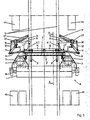
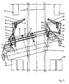
- Fig. 1 shows the Kehr worn 0 under a suggestively illustrated vehicle frame 12 of a sweeping vehicle between the front wheels 44 and the rear wheels 45 with a sweeping roller 1 in a transversely to the longitudinal center axis of the vehicle frame directed thereto mirror image position of the suction wells 2, 2 'and the lever-rod assembly.
- the sweeping roller 1 is arranged and mounted on the support frame 3 '. On both sides of the sweeping roller 1 suction shafts 2, 2 'are provided, which are held on supporting frame spars 3, 4, arranged.
- the support frame spars 3, 4 of the support frame 3 ' are held aligned with a telescoping guide tube 5, the guide tube parts 5', 5 ", the two directions of the longitudinal axis of the guide tube 5 are extendable following the guide tube 5 is via linkages 47, 47 '. connected to piston-cylinder units 14, 15, which allow a telescopic displaceability of the guide tube parts 5 ', 5 "in the guide tube 5 of the support frame 3'.
- the support frame spars 3, 4 are in the position according to Fig. 1 connected by a lever-rod assembly with rigid linkages 27, 27 ', which are fixed to the vehicle frame 12 and in principle allow a horizontal movement of the Kehr worn 0.
- the support frame 3 'of the Kehr sexual 0 is connected to swing 3 "with a vertically directed piston-cylinder units 19 which are connected to pendulum linkages 33 to the vehicle and a movement of the support frame 3' and thus the entire Kehr engaged 0 in
- the lever rod assembly with the linkages 27, 27 'and the support bars 3', 4 ' are provided on both sides mirror images of the longitudinal center axis of the vehicle frame and are in connection with the Fig. 2 only be explained with one page.
- the view according to Fig. 1 shows the symmetrically formed lever-rod assembly, which according to the Fig. 1 is mirror image in starting position and arrangement. It should find the left side of the drawing according to explanation.
- the suction shaft 2 is arranged in a basic position, which is supported by the supporting frame member 3.
- the rods 6, 7, 9 of the lever-rod arrangement are provided one above the other in a vertical plane of the drawing.
- a push rod 9, here in an angled version, is connected via a movable pivot arm 11 with a rigid linkage 10 which is fixedly attached to the linkage 27 and the power transmission in the vehicle frame 12th allowed.
- the pivot arm 11 is moved against a piston-cylinder unit 13, which in turn is connected to the linkage 27.
- the coupling and tie rods 6, 7 are connected via joints with a main pivot arm 8, which is arranged movably on the articulation 27.
- a piston-cylinder unit 17 is provided, which initiates the main pivot arm 8 and, connected thereto, the coupling rod 6 for pivotal movement of the support frame 3 'together with the other rods.
- the drawbar 7 is straight shown for illustrative reasons, but it is actually slightly shaped in the direction of the support frame 3 opposite to the curvature of the push rod 9 to allow a counterforce, as explained later, to stabilize the position of the tilted sweeping device 0.
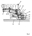
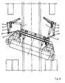
- Fig. 2 shows the section AA in Fig. 1 with a rotation of 90 °.
- the sweeping device 0 stands with its sweeping roller 1 and the support wheels 18 between the vehicle wheels 44, 45 on the road surface 46 on.
- the linkages 27, 33 are fixed to the vehicle frame 12 and keep the sweeping device 0 in a horizontally and vertically variable position.
- the horizontal position is produced by the interaction of the force absorption by the rigid articulation 27 and the vertical force of a piston-cylinder unit 19, which enters via the linkage 33, the vertical forces in the vehicle frame 12.
- the Fig. 2 the view of the inner side of half of the drawing plane right half of the Kehr sensible 0 shows.
- the position of the rocker 3 " is clearly visible, via which the piston-cylinder unit 19 is connected to the support frame 3 'and thus allows the entire device via the linkages and adjustment points 24, 24', 25, 25 ', 26, 26
- the rocker 3 " is movably connected to the support frame spars 4 of the support frame 3 'and enables the horizontal fixing of the support frame 3' with the piston-cylinder unit 19 '. with its functional aggregates.
- a guide tube 5 is arranged below the supporting frame spars 4, which according to the embodiment has a square cross-section and thus keeps the supporting frame 4 torsion-resistant and yet variable in its transverse extension 4 and at one According to this figure, the possible basic positions of the sweeping roller 1 are shown ..
- the sweeping roller 1 is completely lowered and practically assumed that the sweeping roller 1 is processed to a minimum diameter
- the position 22 shows the position of the sweeping roller 1 in its initial size in a lowered position and the position of the sweeping roller 1.
- the suction shaft 2 can be brought behind the working surface of the sweeping roller 1 in each position of the sweeping roller 1 and with its suction mouthpiece 34 in contact with it.
- Fig. 2 clearly shows in the panel level, the gradation of the rod order 6 ', 7', 9 'with their Anlenkungs- and
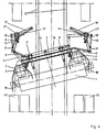
- the Fig. 3 shows the support frame 3 'in a front view.
- the guide tube 5 is shown with retracted guide tube parts 5 ', 5 "and shows the support frame 3' in its smallest transverse extension.
- the support frame spars 3, 4 are connected with their horizontal elements with swinging support wheels 18 and on their vertically rising elements 3, 4 for a Connection with the rods 6, 7, 9.
- the linkages 47, 47 'for the rockers 3 are provided at the central part of the guide tube 5.
- Fig. 3.1 shows the support frame 3 ', but with the right side extended guide tube part 5 "with support frame spars 4.
- the work units receive a flared position, as shown in more detail in the following figures.
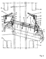
- Fig. 3.2 shows the support frame 3 'in the similar position as Fig. 3 and 3.1 However, here is the support frame spars 3 with the Guide tube part 5 'opposite as in Fig. 3.1 shown, extended.
- the pivoting of the support rollers 18 is of extraordinary importance, as in the explanation of the following figures closer.
- Fig. 4 In FIG. 1, the support frame 3 'is moved from the center position with respect to the longitudinal center axis of the vehicle and pivoted toward the rear vehicle wheel 45 within the periphery of the sweeper.
- the lever rod assembly of the right side is in an approximate position as in Fig. 1 shown in a first movement position.
- the lever rod assembly of the left side is in a starting working position.
- the support frame 3 'with its guide tube parts 5', 5 is retracted in the guide tube 5 and has its normal width, that is, both suction wells 2, 2 'are completely and uniformly maintained in contact with the sweeping roller 1 and the piston-cylinder units 14; 15 in retracted position Not shown here, but off Fig.
- the Fig. 5 shows the Kehr adopted 0 with pivoted support frame 3 'and thus pivoted sweeping roller 1 in an opposite working position as in Fig. 4 ,
- Fig. 5 shows the Kehr adopted 0 with pivoted support frame 3 'and thus pivoted sweeping roller 1 in an opposite working position as in Fig. 4 ,
- Fig. 5 shows the Kehr adopted 0 with pivoted support frame 3 'and thus pivoted sweeping roller 1 in an opposite working position as in Fig. 4 ,
- the mirror image of the same movement and spreading process of the lever-rod assembly has been initiated.
- FIGS. 4 and 5 give the expert the information that now in normal operation with optional side brushes cleaning the road surface is possible if the side brushes put the rubbish in front of the suction ducts 2, 2 ', which is already possible with the known means of the prior art.
- Fig. 6 sets the sweeper 0 under the vehicle frame 12 in accordance with Fig. 5 completed pivoted position to the vehicle 45 before.
- the suction shaft 2 ' is extended laterally with the support roller 18 from the periphery of the vehicle, placed in a working position outside the vehicle width and the suction shaft 2' and the sweeping roller 1 with the support roller 18 projects beyond the vehicle width, but is with the sweeping roller. 1 kept in contact.
- On the opposite side of the guide tube part 5 ' is moved out of the guide tube 5 and the piston-cylinder unit 14 in an extended position.
- the suction shaft 2 is pressed out of the contact position with the sweeping roller 1, because the sweeping roller 1 in the action of extending the guide tube part 5 'with the support frame 3' in the direction of the working side of the suction shaft 2 'is pushed.
- the oscillating design of the linkages 33 of the piston-cylinder unit 19 is responsible with their variable guides that allow a customizable control different positions with their piston rods.
- the coupling rod 6 and the main pivot arm 8 ' are brought into an extended position and the pull rod 7' and the push rod 9 'placed in a position which forms a parallelogram of forces to tensile and compressive forces from the workload in the direction of Propulsion of the Kehr founded to absorb 0 while the pressure from the transverse load of the guide tube part 5 'enter and record on the lever-rod assembly and transferred to the lever-rod assembly ..
- the Fig. 7 shows the Kehr owned 1 in an opposite of Fig. 6 pivoted and extended position and right side taken from the function suction shaft 2 '.
- Fig. 8 shows the Kehr worn 0 in a position as in Fig. 5 is shown.
- the arrangement of play joints has already been explained in order to compensate for design-related and manufacturing tolerances of the lever-rod assembly with their joints, in the interaction of the arrangements in different positions to each other, ie in a kinked or with transitions to emerge in a stretched position.
- the adjustment points 24, 24 ', 25, 25', 26, 26 ' which have already been explained in the preceding embodiments, are largely incorporated for the pre-adjustment and readjustment, however, the possibility of absorbing length deviations caused by the working movements of the Kehr pain arise, not to compensate.
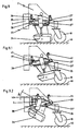
- Fig. 9 shows the arrangement of the suction well 2 of a selected side of a sweeper 0, which is surrounded by a frame 37.
- the frame 37 consists of an inner and outer frame 37 ', 37 ", wherein the inner frame 37' surrounds the suction chute 2 and carries the suction mouthpiece 34.
- a piston-cylinder unit 35 is at the suction mouthpiece 34 via a linkage 41 and with the support frame spar third In a working position, the piston-cylinder unit 35 is extended and the suction mouthpiece 34 is directed straight to the suction chute 2.
- the frame 37 is connected to the support frame spar 3 by means of a linkage 36 and in connection with the function of the pistons
- the joint 38 connects the outer frame 37 "with the support frame spar 3 and the hinge 39, the frame parts 37 ';37” for a scissor-like folding movement together.
- Fig. 9.1 shows the frame 37 in the joint 38 with closed frame parts 37 '; 37 "tilted upward and the stop 42.
- the suction nozzle 34 moves in a pivoting movement, the suction nozzle 34 in a collision with a large-sized rubbish part, for example, a stone back towards the support roller 18th pivoting and raised In this position, the frame 37 is in a compact position in an inclined position.
- Fig. 9.2 is the stroke position of the piston-cylinder unit 35 completed.
- the outer frame 37 "retains the same position as in Fig. 9.1 and the inner frame 37 'is folded over the hinge 39 in a scissor-like position, the stopper 43 leaves its support and the suction shaft 2 with the suction mouthpiece 34 in a Pivoting position opposite to the position as in Fig. 9.1 brought and far from the road surface 46 is removed.
- the illustrated technical detail of the invention allows the suction shaft 2 of the optional not held in working position suction shaft 2, 2 'in a working position according to the FIGS. 6 and 7 To lift and remove from the danger area compact, bulky, lying on the road surface 46 garbage parts to prevent destruction of the suction nozzle 34.
Landscapes
- Engineering & Computer Science (AREA)
- Architecture (AREA)
- Civil Engineering (AREA)
- Structural Engineering (AREA)
- Cleaning In General (AREA)
- Reverberation, Karaoke And Other Acoustics (AREA)
- Electronic Switches (AREA)
- Apparatuses For Bulk Treatment Of Fruits And Vegetables And Apparatuses For Preparing Feeds (AREA)
- Refuse-Collection Vehicles (AREA)
- Cleaning Of Streets, Tracks, Or Beaches (AREA)
- Road Paving Machines (AREA)
Claims (31)
- Equipement de balayage (0) pour une balayeuse à absorption pneumatique, l'équipement de balayage (0) étant équipé d'un rouleau de balayage (1) disposé dans un cadre porteur (3') et dont la position de travail sous la balayeuse est orientée, de façon très largement approximative, transversalement à l'axe médian longitudinal du cadre de balayeuse (12), pivotée selon un angle par rapport à cet axe,
l'équipement de balayage (0) disposant de dispositifs de leviers et de barres ainsi que de jointures (27, 27') rigides, et les dispositifs de leviers et de barres étant équipés de premières et deuxièmes unités de cylindre-piston qui déplacent et retiennent les dispositifs de leviers et de barres pour un mouvement de pivotement du cadre porteur (3'),
et le cadre porteur (3') pouvant être raccordé aux jointures (27 ; 27') rigides et aux dispositifs de leviers et de barres en direction du cadre de véhicule (12),
et un changement de position du cadre porteur (3') pouvant être mis en oeuvre en cas de position horizontale durable du rouleau de balayage (1) jusqu'au positionnement au-dessus de la périphérie latérale de la balayeuse,
caractérisé en ce que
les dispositifs de leviers et de barres sur le cadre porteur (3') sont constitués de façon identique quant à leur position, mais symétriquement de chaque côté, dans plusieurs plans de barres superposés, et en ce que le cadre porteur (3') peut être raccordé de façon pendulaire au cadre de véhicule (12) par le biais de coulisses au moyen de troisièmes unités de cylindre-piston,
le cadre porteur (3') pouvant varier dans son extension transversale au moyen d'un tube de guidage (5) télescopique et étant, au niveau de ses zones latérales, raccordé à des compartiments d'aspiration (2 ; 2') disposés sur des longerons de cadre porteur (3,4),
et les compartiments d'aspiration (2 ; 2') pouvant être amenés, dans un changement de position, près ou loin du rouleau de balayage (1) si l'extension transversale du cadre porteur (3') est modifiée avec des parties de tube de guidage (5', 5") introduites de façon mobile dans le tube de guidage (5). - Equipement de balayage selon la revendication 1, caractérisé en ce que les dispositifs de leviers et de barres sont disposés de chaque côté de l'équipement de balayage (0) de sorte qu'ils sont disposés respectivement entre le cadre porteur (3') avec ses longerons de cadre porteur (3 ; 4) et la jointure (27 ; 27') rigide prévue à cet effet,
les dispositifs de leviers et de barres se composant fondamentalement respectivement d'une barre d'accouplement (6 ; 6'), d'une barre de traction (7 ; 7') ainsi que d'une barre de poussée (9 ; 9') qui forment trois plans de barres placés obliquement par rapport au cadre porteur (3'), la barre de poussée (9 ; 9') étant disposée dans le plan supérieur, la barre de traction (7 ; 7'), en tant que force antagoniste de la barre de poussée (9 ; 9'), dans le plan inférieur, et la barre d'accouplement (6 ; 6') dans le plan médian, et qui sont fixées sur la jointure (27 ; 27') rigide respective par le biais d'un bras pivotant principal (8 ; 8') respectif et d'un bras pivotant (11 ; 11') respectif,
des butées des barres (6 ; 6' ; 7 ; 7' ; 9 ; 9') étant prévues sur des parties verticales respectives des longerons de cadre porteur (3 ; 4) de sorte que les barres (6 ; 6' ; 7 ; 7' ; 9 ; 9') forment un parallélogramme mobile autour des axes verticaux de leurs articulations et bloquent les mouvements horizontaux exécutables en tant que mouvement pivotant et transversal du rouleau de balayage (1) au moyen des premières et deuxièmes unités de cylindre-piston (13 ; 13' ; 16 ; 17) qui travaillent au niveau des bras pivotants principaux (8 ; 8') et des bras pivotants (11 ; 11') dans une interaction indirecte avec les jointures (27 ; 27') rigides,
les compartiments d'aspiration (2 ; 2') étant disposés directement sur les mêmes longerons de cadre porteur (3 ; 4) que les barres (6 ; 6' ; 7 ; 7' ; 9 ; 9') et étant dans une position inversée dans une position de repos transversalement à l'axe médian longitudinal du cadre de véhicule (12) par rapport au rouleau de balayage (1) et étant en contact physique avec le rouleau de balayage (1),
et l'équipement de balayage (0) présentant son extension transversale la plus faible et symétrique quand les parties de tube de guidage (5 ; 5') sont rentrées. - Equipement de balayage selon la revendication 2, caractérisé en ce que les barres (6 ; 6' ; 7 ; 7' ; 9 ; 9') sont articulées sur les longerons de cadre porteur (3, 4) du cadre porteur (3'), et en ce que, pour chaque dispositif de leviers et de barres, la barre de poussée (9 ; 9') courbe située en haut est raccordée au bras pivotant (11 ; 11') respectif, est mise en liaison avec la jointure (27 ; 27') rigide respective par le biais d'un levier de jointure (10 ; 10') rigide et est retenue par la première unité de cylindre-piston (13 ; 13'),
la barre d'accouplement (6 ; 6') située dessous présente une position approximativement parallèle et le même éloignement en longueur entre des jointures constituées comme emplacements d'ajustement (25 ; 25') que la barre de poussée (9 ; 9'), et est raccordée de façon articulée au bras pivotant principal (8 ; 8') et peut être déplacée par le biais de la deuxième unité de cylindre-piston (16; 17) travaillant sur un levier de jointure (16'; 17') rigide,
la barre de traction (7 ; 7') est rapportée de façon mobile sur la partie verticale du longeron de cadre porteur (3 ; 4) au niveau d'un emplacement d'ajustement (26 ; 26') et placée sous la barre d'accouplement (6 ; 6') parallèlement à celle-ci sur le bras pivotant principal (8 ; 8'), et mise en interaction avec celui-ci et avec la barre d'accouplement (6 ; 6'),
le cadre porteur (3') étant, avec des jointures sur les coulisses (3") dans la zone intérieure du cadre porteur (3'), raccordé à la troisième unité cylindre-piston (19), les coulisses (3") étant articulées dans la zone du tube de guidage (5), et veillant à la position verticale et à la position horizontale de l'équipement de balayage (0),
et des quatrièmes unités de cylindre-piston (14 ; 15) étant disposées sur le cadre porteur (3'), dans la zone du tube de guidage (5), en position parallèle avec le tube de guidage (5) et centrées par rapport à lui, et étant raccordées au niveau de leurs côtés opposés aux parties de tube de guidage (5' ; 5"), au moyen desquelles il est possible d'obtenir, par le biais d'un mouvement de type télescopique, une modification de l'extension transversale du cadre porteur (3'). - Equipement de balayage selon les revendications 1 à 3, caractérisé en ce que les longerons de cadre porteur (3 ; 4) sont disposés aux extrémités des parties de tube de guidage (5' ; 5") et présentent des éléments s'étendant horizontalement ainsi que verticalement,
les éléments orientés horizontalement des longerons de cadre porteur (3 ; 4) présentant, pour la fonction porteuse, sur leurs côtés extérieurs, des rouleaux d'appui (18) pivotants qui permettent un appui du cadre porteur (3') sur une surface de chaussée (46),
et les éléments verticaux des longerons de cadre porteur (3 ; 4) étant équipés d'emplacements de palier et d'ajustement pour la jointure des barres (6 ; 6' ; 7 ; 7' ; 9; 9').
et le tube de guidage (5) avec les parties de tube de guidage (5' ; 5") orientées horizontalement présentant dans son axe médian longitudinal des jointures mobiles pour les coulisses (3"),
et les parties de tube de guidage (5' ; 5") étant guidées en glissement dans le tube de guidage (5) de façon mobile indépendamment les unes des autres. - Equipement de balayage selon la revendication 4, caractérisé en ce que le tube de guidage (5) avec les parties de tube de guidage (5' ; 5") présente une section transversale mutuellement protégée en torsion sur l'axe médian longitudinal.
- Equipement de balayage selon les revendications 4 et 5, caractérisé en ce que le tube de guidage (5) avec les parties de tube de guidage (5' ; 5") présente une section transversale carrée.
- Equipement de balayage selon les revendications 4 et 5, caractérisé en ce que le tube de guidage (5) avec les parties de tube de guidage (5' ; 5") présente une section transversale rectangulaire.
- Equipement de balayage selon les revendications 4 et 5, caractérisé en ce que le tube de guidage (5) avec les parties de tube de guidage (5' ; 5") présente une section transversale triangulaire
- Equipement de balayage selon les revendications 4 et 5, caractérisé en ce que le tube de guidage (5) avec les parties de tube de guidage (5' ; 5") présente une section transversale polygonale.
- Equipement de balayage selon les revendications 2 à 4, caractérisé en ce que les barres de traction (7 ; 7') présentent, à peu près au milieu de leur extension longitudinale, une légère courbure qui est constituée de façon opposée à la courbure des barres de poussée (9 ; 9'), les barres de traction (7 ; 7') et les barres de poussée (9 ; 9'), dans une position étirée des barres d'accouplement (6 ; 6') et des bras pivotants (11 ; 11'), constituant mutuellement un parallélogramme, étant amenées à une interaction dans laquelle l'équipement de balayage (0) peut être retenu dans une position de travail bloquée en présence de position du rouleau de balayage (1) pivotée et sortie.
- Equipement de balayage selon la revendication 1 ainsi que selon une ou plusieurs des revendications suivantes, caractérisé en ce que les agencements de leviers et de barres ainsi que les premières et deuxièmes unités de cylindre-piston qui coopèrent avec eux sont prévus de façon fonctionnellement adaptée, inversée, latéralement entre les longerons de cadre porteur (3 ; 4) et les jointures (27 ; 27') rigides.
- Equipement de balayage selon les revendications 1 et 11, caractérisé en ce que les agencements de leviers et de barres sont déplacés et retenus au moyen de premières et deuxièmes unités de cylindre-piston (13 ; 13' ; 16 ; 17) fonctionnant de façon hydraulique.
- Equipement de balayage selon les revendications 1 et 11, caractérisé en ce que, pour le mouvement de traction et de pression des agencements de leviers et de barres, il est prévu des premières et deuxièmes unités de cylindre-piston (13 ; 13' ; 16 ; 17) fonctionnant de façon pneumatique.
- Equipement de balayage selon une des revendications 2-13, caractérisé en ce que les jointures des barres (6 ; 7 ; 9 ; 6' ; 7' ; 9') sont constituées sur les bras pivotants principaux (8 ; 8'), les bras pivotants (11 ; 11') ainsi que sur les éléments verticaux des longerons de cadre porteur (3 ; 4) au moyen de joints universels via des emplacements d'ajustement (24 ; 25 ; 26 ; 24' ; 25' ; 26').
- Equipement de balayage selon une des revendications 2-14, caractérisé en ce que le raccordement de la barre de poussée (9 ; 9') respective au bras pivotant (11 ; 11') correspondant est déplaçable.
- Equipement de balayage selon une des revendications 3-15, caractérisé en ce que le tube de guidage (5) avec ses parties de tube de guidage (5' ; 5") est mobile de façon réciproque sur les quatrièmes unités de cylindre-piston (14 ; 15) placées parallèlement au tube de guidage et disposées de façon contraire, et en ce que, avec le déplacement, une sortie de l'équipement de balayage sur le contour latéral de la balayeuse est réalisable aussi bien avec le compartiment d'aspiration gauche qu'avec le compartiment d'aspiration droit (2 ; 2').
- Equipement de balayage selon les revendications 2 - 15, caractérisé en ce que chaque barre de poussée (9 ; 9') est courbée à environ 90° avec des longueurs de branche différentes, est articulée de façon mobile avec sa branche courte sur le longeron de cadre porteur (3, 4) respectif et, avec sa branche longue, sur le bras pivotant (11 ; 11') respectif, ainsi qu'en ce que chaque barre de traction (7 ; 7') présente une légère courbe avec des longueurs de branche identiques et est intégrée entre le bras pivotant principal (8 ; 8') respectif et le longeron de cadre porteur (3, 4) respectif.
- Equipement de balayage selon la revendication 17, caractérisé en ce que, avec la sortie d'une des parties de tube de guidage (5' ; 5") hors du tube de guidage (5), le rouleau de balayage (1) avec le compartiment d'aspiration (2) peut être amené dans une position faisant saillie à partir de la périphérie de la balayeuse, la barre de poussée (9) pouvant, sur le côté de l'équipement de balayage qui se trouve à l'intérieur de la périphérie de la balayeuse, être amenée dans une position positionnée latéralement et être placée, avec sa longue branche, approximativement transversalement à l'axe médian longitudinal de la balayeuse pour l'absorption de forces transversales en provenance de l'équipement de balayage (0),
et en ce que la barre de traction (7) est placée dans une position approximativement parallèle à l'axe médian longitudinal pour le blocage de la position positionnée de l'équipement de balayage (0),
et, sur le côté de l'équipement de balayage qui se trouve à l'extérieur de la périphérie de la balayeuse, la barre d'accouplement (6') avec le bras pivotant (11') étant déplacée et retenue dans une position étirée par le travail synchronisé des premières et deuxièmes unités de cylindre-piston (13' ; 16'), la barre de poussée (9') avec la barre de traction (7') formant un parallélogramme des forces approximatif et étant amenée, avec la barre d'accouplement (6') située dans la position étirée et avec le bras pivotant principal (8'), en une interaction qui, en correspondance avec les barres de traction et de poussée (7 ; 9) du côté opposé écartées les unes par rapport aux autres, retient l'équipement de balayage (0) dans sa position de pivotement. - Equipement de balayage selon la revendication 18, caractérisé en ce que, sur le côté de l'équipement de balayage qui se trouve à l'intérieur de la périphérie de la balayeuse, la barre de poussée (9) et le bras pivotant (11), au niveau de leur jointure commune, incluent un angle de moins de 90°, et en ce que la barre de traction (7) est dans une position parallèle correspondant à la branche courte de la barre de poussée (9),
la barre de poussée (9) et le bras pivotant (11) formant, avec le bras pivotant principal (8) et la barre d'accouplement (6), un quadrilatère leviers-barres pour absorber les forces longitudinales et transversales qui sont formées à partir de la force de la barre de poussée (9) et sont absorbées par le biais de la partie de tube de guidage (5') sortie,
de sorte que la position transversale de l'équipement de balayage (0) par rapport à l'axe médian longitudinal de la balayeuse peut être maintenue dans une position pivotée,
la barre de traction (7') et la barre de poussée (9') formant, sur le côté de l'équipement de balayage qui se trouve à l'extérieur de la périphérie de la balayeuse, un parallélogramme fermé destiné à absorber les forces transversales, et la barre d'accouplement (6') dans une extension longitudinale étant amenée avec le bras pivotant principal (8') ainsi qu'avec le bras pivotant (11') dans une position étirée, de sorte que l'équipement de balayage (0), dans sa position de pivotement, est fixé dans une position pour absorber des forces provenant de l'activité de balayage et du déplacement vers l'avant du véhicule. - Equipement de balayage selon une des revendications 18 et 19, caractérisé en ce que la barre de poussée (9) ainsi que la barre de traction (7), sur le côté de l'équipement de balayage (0) sur lequel continue à se trouver l'équipement de balayage à l'intérieur de la périphérie de balayeuse quand les parties de tube de guidage (5' ; 5") sont sorties, sont fermées l'une par rapport à l'autre de façon opposée avec leurs courbures,
et en ce que la barre de poussée (9') ainsi que la barre de traction (7'), sur le côté de l'équipement de balayage sur lequel se trouve, quand les parties de tube de guidage (5' ; 5") sont sorties, l'équipement de balayage à l'extérieur de la périphérie de balayeuse, sont ouvertes orientées de façon opposée. - Equipement de balayage selon une des revendications 18-20, caractérisé en ce que le compartiment d'aspiration (2 ; 2') qui suit le mouvement de sortie de sa partie de tube de guidage (5' ; 5") respective, peut être amené à quitter le contact avec le rouleau de balayage (1), le compartiment d'aspiration (2 ; 2') pivoté respectivement sur le côté opposé hors de la périphérie de la balayeuse pouvant être maintenu en contact avec le rouleau de balayage (1) et dans une position de repos.
- Equipement de balayage selon la revendication 2, caractérisé en ce que l'équipement de balayage (0) avec la troisième unité cylindre-piston (19) est mobile verticalement par le biais de coulisses (3"), et en ce que, avec l'agencement des barres d'accouplement, de traction et de poussée (6 ; 6' ; 7 ; 7' ; 9 ; 9') dans plusieurs plans via des emplacements d'ajustement (24 ; 25 ; 26 ; 24' ; 25' ; 25'), il est formé un parallélogramme mobile à plusieurs étages,
et en que les emplacements d'ajustement des deux côtés constituent une ligne de déplacement verticalement parallèle, ce qui fait que le rouleau de balayage (1) et la bouche d'aspiration (34 ; 34') peuvent être amenés dans une position parallèle à la surface de la chaussée (46). - Equipement de balayage selon la revendication 1, caractérisé en ce que le rouleau de balayage (1), avec une cinquième unité de cylindre-piston (20), peut être amené dans une position de pivotement et dans sa position respectivement nécessaire, de façon adaptée en vibration.
- Equipement de balayage selon la revendication 1, caractérisé en ce que les compartiments d'aspiration (2 ; 2') présentent respectivement une bouche d'aspiration (34 ; 34') mobile qui est disposée, retenue dans un cadre (37) formé de parties de cadre (37'; 37"), de façon pivotante au moyen d'une sixième unité de cylindre-piston (35) dans deux étages ainsi que dans des directions opposées.
- Equipement de balayage selon la revendication 24, caractérisé en ce que le cadre (37) englobe la bouche d'aspiration (34 ; 34') du compartiment d'aspiration (2 ; 2') respectif, la bouche d'aspiration (34 ; 34') reposant dans la partie de cadre (37') intérieure qui est raccordée, avec une partie de cadre (37") extérieure, par le biais d'une première articulation (38), à d'autres éléments de l'équipement de balayage (0).
- Equipement de balayage selon la revendication 25, caractérisé en ce que le cadre (37) est raccordé, avec sa partie de cadre (37") extérieur, à l'équipement de balayage (0) par le biais de la première articulation (38) et d'une jointure (36), la partie de cadre (37') intérieure étant raccordée à la partie de cadre (37") extérieure par le biais d'une deuxième articulation (39).
- Equipement de balayage selon la revendication 26, caractérisé en ce que la bouche d'aspiration (34 ; 34'), avec des parties de cadre (37', 37") assemblées du cadre (37), peut, par le biais de la première articulation (38), être amenée dans une première position de pivotement en direction du rouleau d'appui (18) en cas de collision avec un obstacle de grand format.
- Equipement de balayage selon les revendications 26 et 27, caractérisé en ce que la bouche d'aspiration (34 ; 34') peut être amenée, avec son mouvement de levée actif de la sixième unité de cylindre-piston (35) avec la partie de cadre (37') intérieure, à pivoter vers le haut à partir de la partie de cadre (37") extérieure par le biais de la deuxième articulation (39) et peut être déplacée dans une direction opposée au rouleau d'appui (18).
- Equipement de balayage selon une des revendications 26-28, caractérisé en ce que le cadre (37) avec ses parties de cadre (37' ; 37") peut être amené dans une position dépliée d'un côté par le biais de la deuxième articulation (39).
- Equipement de balayage selon une des revendications 24-29, caractérisé en ce que le cadre (37) repose immobile dans la position de départ au moyen de butées (42 ; 43).
- Balayeuse à absorption pneumatique, caractérisée en ce qu'elle englobe un équipement de balayage selon une des revendications 1-30.
Applications Claiming Priority (4)
| Application Number | Priority Date | Filing Date | Title |
|---|---|---|---|
| DE10343712 | 2003-09-21 | ||
| DE10343712 | 2003-09-21 | ||
| DE202004012319U | 2004-08-06 | ||
| DE200420012319 DE202004012319U1 (de) | 2004-08-06 | 2004-08-06 | Einrichtung zum Bewegen des Saugmundstückes einer Kehrmaschine |
Publications (3)
| Publication Number | Publication Date |
|---|---|
| EP1516965A2 EP1516965A2 (fr) | 2005-03-23 |
| EP1516965A3 EP1516965A3 (fr) | 2005-08-31 |
| EP1516965B1 true EP1516965B1 (fr) | 2010-07-07 |
Family
ID=34195763
Family Applications (1)
| Application Number | Title | Priority Date | Filing Date |
|---|---|---|---|
| EP04020961A Expired - Lifetime EP1516965B1 (fr) | 2003-09-21 | 2004-09-03 | Dispositif de balayage pour une balayeuse |
Country Status (3)
| Country | Link |
|---|---|
| EP (1) | EP1516965B1 (fr) |
| AT (1) | ATE473324T1 (fr) |
| DE (1) | DE502004011358D1 (fr) |
Cited By (1)
| Publication number | Priority date | Publication date | Assignee | Title |
|---|---|---|---|---|
| EP4613935A3 (fr) * | 2024-02-16 | 2025-12-10 | Tenax International S.r.l. | Balayeuse |
Families Citing this family (8)
| Publication number | Priority date | Publication date | Assignee | Title |
|---|---|---|---|---|
| DE102008059977A1 (de) * | 2008-11-28 | 2010-06-02 | Faun Viatec Gmbh | Reinigungsfahrzeug |
| DE102009014560A1 (de) | 2009-03-16 | 2010-09-23 | Alfred Kärcher Gmbh & Co. Kg | Auswechselbare Kehrbürsteneinrichtung und Kehrmaschine mit einer derartigen Kehrbürsteneinrichtung |
| WO2010105639A1 (fr) | 2009-03-17 | 2010-09-23 | Alfred Kärcher Gmbh & Co. Kg | Balayeuse automobile |
| CN103362093B (zh) * | 2013-05-31 | 2016-02-24 | 珠海亿华电动车辆有限公司 | 电动地面清扫机 |
| CN106743735A (zh) * | 2017-02-10 | 2017-05-31 | 中冶赛迪工程技术股份有限公司 | 一种带有上带面清扫机构的料场堆料胶带机 |
| CN109914313B (zh) * | 2019-04-19 | 2024-03-26 | 珠海亿华电动车辆有限公司 | 一种用于扫地机的吸盘装置和扫地机 |
| CN112627092B (zh) * | 2020-12-15 | 2023-01-31 | 广东盈峰智能环卫科技有限公司 | 冲洗车 |
| CN120291461B (zh) * | 2025-05-28 | 2025-11-04 | 江苏千诚建设工程有限公司 | 一种市政施工用路面清扫设备 |
Family Cites Families (4)
| Publication number | Priority date | Publication date | Assignee | Title |
|---|---|---|---|---|
| DE7204935U (de) | 1972-05-04 | Keller & Knappich Augsburg | In einer Straßenkehrmaschine vorgesehene Besenwalzen-Halterungsvorrichtung | |
| DE1697227U (de) | 1954-10-01 | 1955-04-28 | Schoerling Waggonbau | Verschiebbare besenwalze fuer kehrmaschinen. |
| DE1774842U (de) | 1958-07-21 | 1958-10-02 | Schoerling & Co Waggonbau | Selbstaufnehmende kehrmaschine fuer die rinnsteinreinigung. |
| GB1592778A (en) * | 1976-11-18 | 1981-07-08 | Johnston Bros Eng Ltd | Refuse collecting vehicles |
-
2004
- 2004-09-03 EP EP04020961A patent/EP1516965B1/fr not_active Expired - Lifetime
- 2004-09-03 DE DE502004011358T patent/DE502004011358D1/de not_active Expired - Lifetime
- 2004-09-03 AT AT04020961T patent/ATE473324T1/de not_active IP Right Cessation
Cited By (1)
| Publication number | Priority date | Publication date | Assignee | Title |
|---|---|---|---|---|
| EP4613935A3 (fr) * | 2024-02-16 | 2025-12-10 | Tenax International S.r.l. | Balayeuse |
Also Published As
| Publication number | Publication date |
|---|---|
| EP1516965A2 (fr) | 2005-03-23 |
| EP1516965A3 (fr) | 2005-08-31 |
| ATE473324T1 (de) | 2010-07-15 |
| DE502004011358D1 (de) | 2010-08-19 |
Similar Documents
| Publication | Publication Date | Title |
|---|---|---|
| EP0336088B1 (fr) | Support de charnière d'un arceau de fermeture intérieure d'une capote | |
| EP0097347B1 (fr) | Châssis porte-outils | |
| DE3048291A1 (de) | "bagger" | |
| EP1715103B1 (fr) | Machine de nettoyage de sols | |
| DE102010034662A1 (de) | Straßenbaumaschine zum Bearbeiten von Fahrbahnen | |
| DE102007059943A1 (de) | Rollstuhlhubvorrichtung | |
| EP1621682B1 (fr) | Appareil de transbordement. | |
| EP1516965B1 (fr) | Dispositif de balayage pour une balayeuse | |
| DE4316364A1 (de) | Mehrzweck-Arbeits-Fahrzeug | |
| EP0467310B1 (fr) | Chasse-neige | |
| EP0590123B1 (fr) | Mecanisme de roulement a ecartement variable | |
| DE202013103571U1 (de) | Boden-Reinigungsmaschine | |
| EP0587175B1 (fr) | Chasse-neige | |
| DE2558029A1 (de) | Strassenreinigungsfahrzeug | |
| EP0727526B1 (fr) | Dispositif de support d'accessoires pour véhicules automobiles utilitaires | |
| DE3924646C2 (fr) | ||
| EP1612335B1 (fr) | Dispositif de balayage automobile | |
| EP2526758B1 (fr) | Faucheuse | |
| DE102004038251A1 (de) | Kehreinrichtung für eine Kehrmaschine | |
| DE2633683A1 (de) | Transportfahrzeug fuer fertiggaragen und dergleichen | |
| DE1534167B1 (de) | An Fahrzeugen anbaubare und hoehenverstellbare Vorrichtung zum Abschaben von auf Fahrbahnen befindlichen festgefahrenen Verunreinigungen bzw. Verkrustungen | |
| EP0580978A1 (fr) | Chasse-neige | |
| DE2243290A1 (de) | Transportvorrichtung | |
| DE10219214B4 (de) | Knickgelenktes Baufahrzeug | |
| AT403710B (de) | Schneepflug mit verschwenkbarer seitenpflugschar |
Legal Events
| Date | Code | Title | Description |
|---|---|---|---|
| PUAI | Public reference made under article 153(3) epc to a published international application that has entered the european phase |
Free format text: ORIGINAL CODE: 0009012 |
|
| AK | Designated contracting states |
Kind code of ref document: A2 Designated state(s): AT BE BG CH CY CZ DE DK EE ES FI FR GB GR HU IE IT LI LU MC NL PL PT RO SE SI SK TR |
|
| AX | Request for extension of the european patent |
Extension state: AL HR LT LV MK |
|
| PUAL | Search report despatched |
Free format text: ORIGINAL CODE: 0009013 |
|
| 17P | Request for examination filed |
Effective date: 20050603 |
|
| AK | Designated contracting states |
Kind code of ref document: A3 Designated state(s): AT BE BG CH CY CZ DE DK EE ES FI FR GB GR HU IE IT LI LU MC NL PL PT RO SE SI SK TR |
|
| AX | Request for extension of the european patent |
Extension state: AL HR LT LV MK |
|
| AKX | Designation fees paid |
Designated state(s): AT BE BG CH CY CZ DE DK EE ES FI FR GB GR HU IE IT LI LU MC NL PL PT RO SE SI SK TR |
|
| AXX | Extension fees paid |
Extension state: LT Payment date: 20050301 Extension state: LV Payment date: 20050301 |
|
| 17Q | First examination report despatched |
Effective date: 20061222 |
|
| RAP1 | Party data changed (applicant data changed or rights of an application transferred) |
Owner name: HSW SPEZIAL FAHRZEUG- UND GERAETEBAU GMBH & CO. KG |
|
| GRAP | Despatch of communication of intention to grant a patent |
Free format text: ORIGINAL CODE: EPIDOSNIGR1 |
|
| GRAS | Grant fee paid |
Free format text: ORIGINAL CODE: EPIDOSNIGR3 |
|
| RIN1 | Information on inventor provided before grant (corrected) |
Inventor name: ALBRECHT, BERT |
|
| GRAA | (expected) grant |
Free format text: ORIGINAL CODE: 0009210 |
|
| AK | Designated contracting states |
Kind code of ref document: B1 Designated state(s): AT BE BG CH CY CZ DE DK EE ES FI FR GB GR HU IE IT LI LU MC NL PL PT RO SE SI SK TR |
|
| AX | Request for extension of the european patent |
Extension state: LT LV |
|
| REG | Reference to a national code |
Ref country code: GB Ref legal event code: FG4D Free format text: NOT ENGLISH |
|
| REG | Reference to a national code |
Ref country code: CH Ref legal event code: EP |
|
| RAP2 | Party data changed (patent owner data changed or rights of a patent transferred) |
Owner name: HSW SPEZIAL FAHRZEUG- UND GERAETEBAU GMBH & CO. KG |
|
| REG | Reference to a national code |
Ref country code: IE Ref legal event code: FG4D |
|
| REF | Corresponds to: |
Ref document number: 502004011358 Country of ref document: DE Date of ref document: 20100819 Kind code of ref document: P |
|
| REG | Reference to a national code |
Ref country code: NL Ref legal event code: VDEP Effective date: 20100707 |
|
| PG25 | Lapsed in a contracting state [announced via postgrant information from national office to epo] |
Ref country code: SI Free format text: LAPSE BECAUSE OF FAILURE TO SUBMIT A TRANSLATION OF THE DESCRIPTION OR TO PAY THE FEE WITHIN THE PRESCRIBED TIME-LIMIT Effective date: 20100707 |
|
| LTIE | Lt: invalidation of european patent or patent extension |
Effective date: 20100707 |
|
| PG25 | Lapsed in a contracting state [announced via postgrant information from national office to epo] |
Ref country code: FI Free format text: LAPSE BECAUSE OF FAILURE TO SUBMIT A TRANSLATION OF THE DESCRIPTION OR TO PAY THE FEE WITHIN THE PRESCRIBED TIME-LIMIT Effective date: 20100707 Ref country code: NL Free format text: LAPSE BECAUSE OF FAILURE TO SUBMIT A TRANSLATION OF THE DESCRIPTION OR TO PAY THE FEE WITHIN THE PRESCRIBED TIME-LIMIT Effective date: 20100707 |
|
| REG | Reference to a national code |
Ref country code: IE Ref legal event code: FD4D |
|
| PG25 | Lapsed in a contracting state [announced via postgrant information from national office to epo] |
Ref country code: BG Free format text: LAPSE BECAUSE OF FAILURE TO SUBMIT A TRANSLATION OF THE DESCRIPTION OR TO PAY THE FEE WITHIN THE PRESCRIBED TIME-LIMIT Effective date: 20101007 Ref country code: CY Free format text: LAPSE BECAUSE OF FAILURE TO SUBMIT A TRANSLATION OF THE DESCRIPTION OR TO PAY THE FEE WITHIN THE PRESCRIBED TIME-LIMIT Effective date: 20100707 Ref country code: PL Free format text: LAPSE BECAUSE OF FAILURE TO SUBMIT A TRANSLATION OF THE DESCRIPTION OR TO PAY THE FEE WITHIN THE PRESCRIBED TIME-LIMIT Effective date: 20100707 Ref country code: PT Free format text: LAPSE BECAUSE OF FAILURE TO SUBMIT A TRANSLATION OF THE DESCRIPTION OR TO PAY THE FEE WITHIN THE PRESCRIBED TIME-LIMIT Effective date: 20101108 |
|
| PGFP | Annual fee paid to national office [announced via postgrant information from national office to epo] |
Ref country code: DE Payment date: 20101026 Year of fee payment: 7 |
|
| BERE | Be: lapsed |
Owner name: HSW SPEZIAL FAHRZEUG- UND GERATEBAU G.M.B.H. & CO. Effective date: 20100930 |
|
| PG25 | Lapsed in a contracting state [announced via postgrant information from national office to epo] |
Ref country code: GR Free format text: LAPSE BECAUSE OF FAILURE TO SUBMIT A TRANSLATION OF THE DESCRIPTION OR TO PAY THE FEE WITHIN THE PRESCRIBED TIME-LIMIT Effective date: 20101008 Ref country code: SE Free format text: LAPSE BECAUSE OF FAILURE TO SUBMIT A TRANSLATION OF THE DESCRIPTION OR TO PAY THE FEE WITHIN THE PRESCRIBED TIME-LIMIT Effective date: 20100707 |
|
| PG25 | Lapsed in a contracting state [announced via postgrant information from national office to epo] |
Ref country code: MC Free format text: LAPSE BECAUSE OF NON-PAYMENT OF DUE FEES Effective date: 20100930 Ref country code: IE Free format text: LAPSE BECAUSE OF FAILURE TO SUBMIT A TRANSLATION OF THE DESCRIPTION OR TO PAY THE FEE WITHIN THE PRESCRIBED TIME-LIMIT Effective date: 20100707 Ref country code: DK Free format text: LAPSE BECAUSE OF FAILURE TO SUBMIT A TRANSLATION OF THE DESCRIPTION OR TO PAY THE FEE WITHIN THE PRESCRIBED TIME-LIMIT Effective date: 20100707 |
|
| REG | Reference to a national code |
Ref country code: CH Ref legal event code: PL |
|
| PLBE | No opposition filed within time limit |
Free format text: ORIGINAL CODE: 0009261 |
|
| STAA | Information on the status of an ep patent application or granted ep patent |
Free format text: STATUS: NO OPPOSITION FILED WITHIN TIME LIMIT |
|
| PG25 | Lapsed in a contracting state [announced via postgrant information from national office to epo] |
Ref country code: RO Free format text: LAPSE BECAUSE OF FAILURE TO SUBMIT A TRANSLATION OF THE DESCRIPTION OR TO PAY THE FEE WITHIN THE PRESCRIBED TIME-LIMIT Effective date: 20100707 Ref country code: SK Free format text: LAPSE BECAUSE OF FAILURE TO SUBMIT A TRANSLATION OF THE DESCRIPTION OR TO PAY THE FEE WITHIN THE PRESCRIBED TIME-LIMIT Effective date: 20100707 Ref country code: CZ Free format text: LAPSE BECAUSE OF FAILURE TO SUBMIT A TRANSLATION OF THE DESCRIPTION OR TO PAY THE FEE WITHIN THE PRESCRIBED TIME-LIMIT Effective date: 20100707 Ref country code: EE Free format text: LAPSE BECAUSE OF FAILURE TO SUBMIT A TRANSLATION OF THE DESCRIPTION OR TO PAY THE FEE WITHIN THE PRESCRIBED TIME-LIMIT Effective date: 20100707 Ref country code: IT Free format text: LAPSE BECAUSE OF FAILURE TO SUBMIT A TRANSLATION OF THE DESCRIPTION OR TO PAY THE FEE WITHIN THE PRESCRIBED TIME-LIMIT Effective date: 20100707 |
|
| 26N | No opposition filed |
Effective date: 20110408 |
|
| REG | Reference to a national code |
Ref country code: FR Ref legal event code: ST Effective date: 20110531 |
|
| GBPC | Gb: european patent ceased through non-payment of renewal fee |
Effective date: 20101007 |
|
| PG25 | Lapsed in a contracting state [announced via postgrant information from national office to epo] |
Ref country code: ES Free format text: LAPSE BECAUSE OF FAILURE TO SUBMIT A TRANSLATION OF THE DESCRIPTION OR TO PAY THE FEE WITHIN THE PRESCRIBED TIME-LIMIT Effective date: 20101018 |
|
| REG | Reference to a national code |
Ref country code: DE Ref legal event code: R097 Ref document number: 502004011358 Country of ref document: DE Effective date: 20110408 |
|
| PG25 | Lapsed in a contracting state [announced via postgrant information from national office to epo] |
Ref country code: BE Free format text: LAPSE BECAUSE OF NON-PAYMENT OF DUE FEES Effective date: 20100930 Ref country code: FR Free format text: LAPSE BECAUSE OF NON-PAYMENT OF DUE FEES Effective date: 20100930 Ref country code: CH Free format text: LAPSE BECAUSE OF NON-PAYMENT OF DUE FEES Effective date: 20100930 Ref country code: LI Free format text: LAPSE BECAUSE OF NON-PAYMENT OF DUE FEES Effective date: 20100930 |
|
| PG25 | Lapsed in a contracting state [announced via postgrant information from national office to epo] |
Ref country code: GB Free format text: LAPSE BECAUSE OF NON-PAYMENT OF DUE FEES Effective date: 20101007 |
|
| PG25 | Lapsed in a contracting state [announced via postgrant information from national office to epo] |
Ref country code: AT Free format text: LAPSE BECAUSE OF NON-PAYMENT OF DUE FEES Effective date: 20100903 |
|
| REG | Reference to a national code |
Ref country code: DE Ref legal event code: R119 Ref document number: 502004011358 Country of ref document: DE Effective date: 20120403 |
|
| PG25 | Lapsed in a contracting state [announced via postgrant information from national office to epo] |
Ref country code: DE Free format text: LAPSE BECAUSE OF NON-PAYMENT OF DUE FEES Effective date: 20120403 |
|
| PG25 | Lapsed in a contracting state [announced via postgrant information from national office to epo] |
Ref country code: LU Free format text: LAPSE BECAUSE OF NON-PAYMENT OF DUE FEES Effective date: 20100903 Ref country code: HU Free format text: LAPSE BECAUSE OF FAILURE TO SUBMIT A TRANSLATION OF THE DESCRIPTION OR TO PAY THE FEE WITHIN THE PRESCRIBED TIME-LIMIT Effective date: 20110108 |
|
| PG25 | Lapsed in a contracting state [announced via postgrant information from national office to epo] |
Ref country code: TR Free format text: LAPSE BECAUSE OF FAILURE TO SUBMIT A TRANSLATION OF THE DESCRIPTION OR TO PAY THE FEE WITHIN THE PRESCRIBED TIME-LIMIT Effective date: 20100707 |