EP1516984A2 - Notentriegelungsvorrichtung für Ver- und Entriegelungssysteme für Schwenkschiebetüren, insbesondere für Schienenfahrzeuge - Google Patents
Notentriegelungsvorrichtung für Ver- und Entriegelungssysteme für Schwenkschiebetüren, insbesondere für Schienenfahrzeuge Download PDFInfo
- Publication number
- EP1516984A2 EP1516984A2 EP04021678A EP04021678A EP1516984A2 EP 1516984 A2 EP1516984 A2 EP 1516984A2 EP 04021678 A EP04021678 A EP 04021678A EP 04021678 A EP04021678 A EP 04021678A EP 1516984 A2 EP1516984 A2 EP 1516984A2
- Authority
- EP
- European Patent Office
- Prior art keywords
- lever
- pivot
- bolt
- locking
- emergency
- Prior art date
- Legal status (The legal status is an assumption and is not a legal conclusion. Google has not performed a legal analysis and makes no representation as to the accuracy of the status listed.)
- Withdrawn
Links
Images


Classifications
-
- B—PERFORMING OPERATIONS; TRANSPORTING
- B61—RAILWAYS
- B61D—BODY DETAILS OR KINDS OF RAILWAY VEHICLES
- B61D19/00—Door arrangements specially adapted for rail vehicles
- B61D19/003—Door arrangements specially adapted for rail vehicles characterised by the movements of the door
- B61D19/008—Door arrangements specially adapted for rail vehicles characterised by the movements of the door both swinging and sliding
-
- E—FIXED CONSTRUCTIONS
- E05—LOCKS; KEYS; WINDOW OR DOOR FITTINGS; SAFES
- E05B—LOCKS; ACCESSORIES THEREFOR; HANDCUFFS
- E05B79/00—Mounting or connecting vehicle locks or parts thereof
- E05B79/10—Connections between movable lock parts
- E05B79/20—Connections between movable lock parts using flexible connections, e.g. Bowden cables
-
- E—FIXED CONSTRUCTIONS
- E05—LOCKS; KEYS; WINDOW OR DOOR FITTINGS; SAFES
- E05B—LOCKS; ACCESSORIES THEREFOR; HANDCUFFS
- E05B83/00—Vehicle locks specially adapted for particular types of wing or vehicle
- E05B83/36—Locks for passenger or like doors
- E05B83/363—Locks for passenger or like doors for railway vehicles
-
- E—FIXED CONSTRUCTIONS
- E05—LOCKS; KEYS; WINDOW OR DOOR FITTINGS; SAFES
- E05B—LOCKS; ACCESSORIES THEREFOR; HANDCUFFS
- E05B83/00—Vehicle locks specially adapted for particular types of wing or vehicle
- E05B83/36—Locks for passenger or like doors
- E05B83/40—Locks for passenger or like doors for sliding doors
-
- E—FIXED CONSTRUCTIONS
- E05—LOCKS; KEYS; WINDOW OR DOOR FITTINGS; SAFES
- E05D—HINGES OR SUSPENSION DEVICES FOR DOORS, WINDOWS OR WINGS
- E05D15/00—Suspension arrangements for wings
- E05D15/06—Suspension arrangements for wings for wings sliding horizontally more or less in their own plane
- E05D15/10—Suspension arrangements for wings for wings sliding horizontally more or less in their own plane movable out of one plane into a second parallel plane
- E05D15/1065—Suspension arrangements for wings for wings sliding horizontally more or less in their own plane movable out of one plane into a second parallel plane with transversely moving track
- E05D15/1068—Suspension arrangements for wings for wings sliding horizontally more or less in their own plane movable out of one plane into a second parallel plane with transversely moving track specially adapted for use in railway-cars or mass transit vehicles
-
- E—FIXED CONSTRUCTIONS
- E05—LOCKS; KEYS; WINDOW OR DOOR FITTINGS; SAFES
- E05F—DEVICES FOR MOVING WINGS INTO OPEN OR CLOSED POSITION; CHECKS FOR WINGS; WING FITTINGS NOT OTHERWISE PROVIDED FOR, CONCERNED WITH THE FUNCTIONING OF THE WING
- E05F15/00—Power-operated mechanisms for wings
- E05F15/60—Power-operated mechanisms for wings using electrical actuators
- E05F15/603—Power-operated mechanisms for wings using electrical actuators using rotary electromotors
- E05F15/632—Power-operated mechanisms for wings using electrical actuators using rotary electromotors for horizontally-sliding wings
- E05F15/635—Power-operated mechanisms for wings using electrical actuators using rotary electromotors for horizontally-sliding wings operated by push-pull mechanisms, e.g. flexible or rigid rack-and-pinion arrangements
- E05F15/638—Power-operated mechanisms for wings using electrical actuators using rotary electromotors for horizontally-sliding wings operated by push-pull mechanisms, e.g. flexible or rigid rack-and-pinion arrangements allowing or involving a secondary movement of the wing, e.g. rotational or transversal
-
- E—FIXED CONSTRUCTIONS
- E05—LOCKS; KEYS; WINDOW OR DOOR FITTINGS; SAFES
- E05B—LOCKS; ACCESSORIES THEREFOR; HANDCUFFS
- E05B53/00—Operation or control of locks by mechanical transmissions, e.g. from a distance
-
- E—FIXED CONSTRUCTIONS
- E05—LOCKS; KEYS; WINDOW OR DOOR FITTINGS; SAFES
- E05B—LOCKS; ACCESSORIES THEREFOR; HANDCUFFS
- E05B63/00—Locks or fastenings with special structural characteristics
- E05B63/0052—Locks mounted on the "frame" cooperating with means on the "wing"
-
- E—FIXED CONSTRUCTIONS
- E05—LOCKS; KEYS; WINDOW OR DOOR FITTINGS; SAFES
- E05B—LOCKS; ACCESSORIES THEREFOR; HANDCUFFS
- E05B63/00—Locks or fastenings with special structural characteristics
- E05B63/14—Arrangement of several locks or locks with several bolts, e.g. arranged one behind the other
- E05B63/143—Arrangement of several locks, e.g. in parallel or series, on one or more wings
-
- E—FIXED CONSTRUCTIONS
- E05—LOCKS; KEYS; WINDOW OR DOOR FITTINGS; SAFES
- E05B—LOCKS; ACCESSORIES THEREFOR; HANDCUFFS
- E05B65/00—Locks or fastenings for special use
- E05B65/08—Locks or fastenings for special use for sliding wings
- E05B65/0835—Locks or fastenings for special use for sliding wings the bolts pivoting about an axis parallel to the wings
-
- E—FIXED CONSTRUCTIONS
- E05—LOCKS; KEYS; WINDOW OR DOOR FITTINGS; SAFES
- E05B—LOCKS; ACCESSORIES THEREFOR; HANDCUFFS
- E05B81/00—Power-actuated vehicle locks
- E05B81/12—Power-actuated vehicle locks characterised by the function or purpose of the powered actuators
- E05B81/20—Power-actuated vehicle locks characterised by the function or purpose of the powered actuators for assisting final closing or for initiating opening
-
- E—FIXED CONSTRUCTIONS
- E05—LOCKS; KEYS; WINDOW OR DOOR FITTINGS; SAFES
- E05B—LOCKS; ACCESSORIES THEREFOR; HANDCUFFS
- E05B81/00—Power-actuated vehicle locks
- E05B81/54—Electrical circuits
- E05B81/90—Manual override in case of power failure
-
- E—FIXED CONSTRUCTIONS
- E05—LOCKS; KEYS; WINDOW OR DOOR FITTINGS; SAFES
- E05C—BOLTS OR FASTENING DEVICES FOR WINGS, SPECIALLY FOR DOORS OR WINDOWS
- E05C7/00—Fastening devices specially adapted for two wings
- E05C2007/007—Fastening devices specially adapted for two wings for a double-wing sliding door or window, i.e. where both wings are slidable
-
- E—FIXED CONSTRUCTIONS
- E05—LOCKS; KEYS; WINDOW OR DOOR FITTINGS; SAFES
- E05C—BOLTS OR FASTENING DEVICES FOR WINGS, SPECIALLY FOR DOORS OR WINDOWS
- E05C3/00—Fastening devices with bolts moving pivotally or rotatively
- E05C3/12—Fastening devices with bolts moving pivotally or rotatively with latching action
- E05C3/16—Fastening devices with bolts moving pivotally or rotatively with latching action with operating handle or equivalent member moving otherwise than rigidly with the latch
- E05C3/22—Fastening devices with bolts moving pivotally or rotatively with latching action with operating handle or equivalent member moving otherwise than rigidly with the latch the bolt being spring controlled
- E05C3/24—Fastening devices with bolts moving pivotally or rotatively with latching action with operating handle or equivalent member moving otherwise than rigidly with the latch the bolt being spring controlled in the form of a bifurcated member
-
- E—FIXED CONSTRUCTIONS
- E05—LOCKS; KEYS; WINDOW OR DOOR FITTINGS; SAFES
- E05F—DEVICES FOR MOVING WINGS INTO OPEN OR CLOSED POSITION; CHECKS FOR WINGS; WING FITTINGS NOT OTHERWISE PROVIDED FOR, CONCERNED WITH THE FUNCTIONING OF THE WING
- E05F15/00—Power-operated mechanisms for wings
- E05F15/60—Power-operated mechanisms for wings using electrical actuators
- E05F15/603—Power-operated mechanisms for wings using electrical actuators using rotary electromotors
- E05F15/632—Power-operated mechanisms for wings using electrical actuators using rotary electromotors for horizontally-sliding wings
- E05F15/643—Power-operated mechanisms for wings using electrical actuators using rotary electromotors for horizontally-sliding wings operated by flexible elongated pulling elements, e.g. belts, chains or cables
- E05F15/646—Power-operated mechanisms for wings using electrical actuators using rotary electromotors for horizontally-sliding wings operated by flexible elongated pulling elements, e.g. belts, chains or cables allowing or involving a secondary movement of the wing, e.g. rotational or transversal
-
- E—FIXED CONSTRUCTIONS
- E05—LOCKS; KEYS; WINDOW OR DOOR FITTINGS; SAFES
- E05F—DEVICES FOR MOVING WINGS INTO OPEN OR CLOSED POSITION; CHECKS FOR WINGS; WING FITTINGS NOT OTHERWISE PROVIDED FOR, CONCERNED WITH THE FUNCTIONING OF THE WING
- E05F17/00—Special devices for shifting a plurality of wings operated simultaneously
- E05F17/004—Special devices for shifting a plurality of wings operated simultaneously for wings which abut when closed
-
- E—FIXED CONSTRUCTIONS
- E05—LOCKS; KEYS; WINDOW OR DOOR FITTINGS; SAFES
- E05Y—INDEXING SCHEME ASSOCIATED WITH SUBCLASSES E05D AND E05F, RELATING TO CONSTRUCTION ELEMENTS, ELECTRIC CONTROL, POWER SUPPLY, POWER SIGNAL OR TRANSMISSION, USER INTERFACES, MOUNTING OR COUPLING, DETAILS, ACCESSORIES, AUXILIARY OPERATIONS NOT OTHERWISE PROVIDED FOR, APPLICATION THEREOF
- E05Y2201/00—Constructional elements; Accessories therefor
- E05Y2201/20—Brakes; Disengaging means; Holders; Stops; Valves; Accessories therefor
- E05Y2201/218—Holders
- E05Y2201/22—Locks
-
- E—FIXED CONSTRUCTIONS
- E05—LOCKS; KEYS; WINDOW OR DOOR FITTINGS; SAFES
- E05Y—INDEXING SCHEME ASSOCIATED WITH SUBCLASSES E05D AND E05F, RELATING TO CONSTRUCTION ELEMENTS, ELECTRIC CONTROL, POWER SUPPLY, POWER SIGNAL OR TRANSMISSION, USER INTERFACES, MOUNTING OR COUPLING, DETAILS, ACCESSORIES, AUXILIARY OPERATIONS NOT OTHERWISE PROVIDED FOR, APPLICATION THEREOF
- E05Y2201/00—Constructional elements; Accessories therefor
- E05Y2201/20—Brakes; Disengaging means; Holders; Stops; Valves; Accessories therefor
- E05Y2201/23—Actuation thereof
- E05Y2201/232—Actuation thereof by automatically acting means
- E05Y2201/236—Actuation thereof by automatically acting means using force or torque
- E05Y2201/238—Actuation thereof by automatically acting means using force or torque reaction force or torque
-
- E—FIXED CONSTRUCTIONS
- E05—LOCKS; KEYS; WINDOW OR DOOR FITTINGS; SAFES
- E05Y—INDEXING SCHEME ASSOCIATED WITH SUBCLASSES E05D AND E05F, RELATING TO CONSTRUCTION ELEMENTS, ELECTRIC CONTROL, POWER SUPPLY, POWER SIGNAL OR TRANSMISSION, USER INTERFACES, MOUNTING OR COUPLING, DETAILS, ACCESSORIES, AUXILIARY OPERATIONS NOT OTHERWISE PROVIDED FOR, APPLICATION THEREOF
- E05Y2201/00—Constructional elements; Accessories therefor
- E05Y2201/20—Brakes; Disengaging means; Holders; Stops; Valves; Accessories therefor
- E05Y2201/23—Actuation thereof
- E05Y2201/244—Actuation thereof by manual operation
-
- E—FIXED CONSTRUCTIONS
- E05—LOCKS; KEYS; WINDOW OR DOOR FITTINGS; SAFES
- E05Y—INDEXING SCHEME ASSOCIATED WITH SUBCLASSES E05D AND E05F, RELATING TO CONSTRUCTION ELEMENTS, ELECTRIC CONTROL, POWER SUPPLY, POWER SIGNAL OR TRANSMISSION, USER INTERFACES, MOUNTING OR COUPLING, DETAILS, ACCESSORIES, AUXILIARY OPERATIONS NOT OTHERWISE PROVIDED FOR, APPLICATION THEREOF
- E05Y2201/00—Constructional elements; Accessories therefor
- E05Y2201/40—Motors; Magnets; Springs; Weights; Accessories therefor
- E05Y2201/43—Motors
- E05Y2201/434—Electromotors; Details thereof
-
- E—FIXED CONSTRUCTIONS
- E05—LOCKS; KEYS; WINDOW OR DOOR FITTINGS; SAFES
- E05Y—INDEXING SCHEME ASSOCIATED WITH SUBCLASSES E05D AND E05F, RELATING TO CONSTRUCTION ELEMENTS, ELECTRIC CONTROL, POWER SUPPLY, POWER SIGNAL OR TRANSMISSION, USER INTERFACES, MOUNTING OR COUPLING, DETAILS, ACCESSORIES, AUXILIARY OPERATIONS NOT OTHERWISE PROVIDED FOR, APPLICATION THEREOF
- E05Y2600/00—Mounting or coupling arrangements for elements provided for in this subclass
- E05Y2600/10—Adjustable
- E05Y2600/11—Adjustable by automatically acting means
-
- E—FIXED CONSTRUCTIONS
- E05—LOCKS; KEYS; WINDOW OR DOOR FITTINGS; SAFES
- E05Y—INDEXING SCHEME ASSOCIATED WITH SUBCLASSES E05D AND E05F, RELATING TO CONSTRUCTION ELEMENTS, ELECTRIC CONTROL, POWER SUPPLY, POWER SIGNAL OR TRANSMISSION, USER INTERFACES, MOUNTING OR COUPLING, DETAILS, ACCESSORIES, AUXILIARY OPERATIONS NOT OTHERWISE PROVIDED FOR, APPLICATION THEREOF
- E05Y2600/00—Mounting or coupling arrangements for elements provided for in this subclass
- E05Y2600/10—Adjustable
- E05Y2600/30—Adjustment motion
- E05Y2600/32—Rotary motion
- E05Y2600/322—Rotary motion around a horizontal axis
-
- E—FIXED CONSTRUCTIONS
- E05—LOCKS; KEYS; WINDOW OR DOOR FITTINGS; SAFES
- E05Y—INDEXING SCHEME ASSOCIATED WITH SUBCLASSES E05D AND E05F, RELATING TO CONSTRUCTION ELEMENTS, ELECTRIC CONTROL, POWER SUPPLY, POWER SIGNAL OR TRANSMISSION, USER INTERFACES, MOUNTING OR COUPLING, DETAILS, ACCESSORIES, AUXILIARY OPERATIONS NOT OTHERWISE PROVIDED FOR, APPLICATION THEREOF
- E05Y2600/00—Mounting or coupling arrangements for elements provided for in this subclass
- E05Y2600/40—Mounting location; Visibility of the elements
- E05Y2600/46—Mounting location; Visibility of the elements in or on the wing
-
- E—FIXED CONSTRUCTIONS
- E05—LOCKS; KEYS; WINDOW OR DOOR FITTINGS; SAFES
- E05Y—INDEXING SCHEME ASSOCIATED WITH SUBCLASSES E05D AND E05F, RELATING TO CONSTRUCTION ELEMENTS, ELECTRIC CONTROL, POWER SUPPLY, POWER SIGNAL OR TRANSMISSION, USER INTERFACES, MOUNTING OR COUPLING, DETAILS, ACCESSORIES, AUXILIARY OPERATIONS NOT OTHERWISE PROVIDED FOR, APPLICATION THEREOF
- E05Y2800/00—Details, accessories and auxiliary operations not otherwise provided for
- E05Y2800/25—Emergency conditions
-
- E—FIXED CONSTRUCTIONS
- E05—LOCKS; KEYS; WINDOW OR DOOR FITTINGS; SAFES
- E05Y—INDEXING SCHEME ASSOCIATED WITH SUBCLASSES E05D AND E05F, RELATING TO CONSTRUCTION ELEMENTS, ELECTRIC CONTROL, POWER SUPPLY, POWER SIGNAL OR TRANSMISSION, USER INTERFACES, MOUNTING OR COUPLING, DETAILS, ACCESSORIES, AUXILIARY OPERATIONS NOT OTHERWISE PROVIDED FOR, APPLICATION THEREOF
- E05Y2800/00—Details, accessories and auxiliary operations not otherwise provided for
- E05Y2800/73—Multiple functions
-
- E—FIXED CONSTRUCTIONS
- E05—LOCKS; KEYS; WINDOW OR DOOR FITTINGS; SAFES
- E05Y—INDEXING SCHEME ASSOCIATED WITH SUBCLASSES E05D AND E05F, RELATING TO CONSTRUCTION ELEMENTS, ELECTRIC CONTROL, POWER SUPPLY, POWER SIGNAL OR TRANSMISSION, USER INTERFACES, MOUNTING OR COUPLING, DETAILS, ACCESSORIES, AUXILIARY OPERATIONS NOT OTHERWISE PROVIDED FOR, APPLICATION THEREOF
- E05Y2900/00—Application of doors, windows, wings or fittings thereof
- E05Y2900/50—Application of doors, windows, wings or fittings thereof for vehicles
- E05Y2900/51—Application of doors, windows, wings or fittings thereof for vehicles for railway cars or mass transit vehicles
Definitions
- the invention relates to an emergency release device for and Entriegelungssysteme for sliding doors, especially of rail vehicles.
- an emergency release device (DE 197 45 753 C2) with a second drive as a pneumatic actuator that the Notbetuschistsorgan from the Locking position is moved to a position lying in the dead center position, out of the manual operation of the door leaf takes place.
- the invention is based on the object, a simple and inexpensive emergency release to create, which is characterized by a high reliability. According to the invention, the object is achieved by the features specified in claim 1 solved. Advantageous embodiments and developments are the subject of Claims 2 to 15.
- the emergency unlocking device consists of a lever system, with a first spring-loaded pivot lever on which the traction means, preferably a Bowden cable, attacks.
- This lever is connected via a second lever with a third lever, wherein the third lever on the axial shaft of a spring-loaded rotary magnet is attached and has slots.
- a bolt is displaceable stored, which at a tensile stress of the traction means with a on a shaft pivotally mounted fourth lever engages and moves this.
- the fourth Lever is at least one horizontally arranged coupling rod and deflection with a vertically movable locking bar in operative connection. At the fourth lever still attacks a rod on the temporarily one the locking and unlocking of the door leaves causing force component can be introduced.
- the proposed lever system for emergency release can be as compact and separate assembly for different locking and unlocking devices be used. Another advantage is that it is only a relatively small one Installation space takes.
- the operation of the emergency release can be done manually via a Bowden cable, which is attached to the first pivot lever.
- the complete lever system can be mounted on a mounting plate or a carrier element to be assembled.
- the fourth lever can additionally as a functional element for the Locking and unlocking device can be used.
- the second lever is a bent tab formed in the first pivot lever offset from the axis of rotation pivotally is held.
- the bolt At the protruding end of the tab is the bolt in arranged in vertical direction, in operative connection with the third lever stands, which serves as a horizontal guide recess and congruent Has long holes as a vertical guide.
- the fourth lever has on his to the third pivot lever end facing a semicircular or claw-shaped Recess which intermittently engaged with the guided in the second lever bolt stands.
- the first lever, the third lever and the fourth lever are pivoting levers formed on a horizontally disposed plate or a support element are stored.
- the fourth pivot lever engages opposite to the recess the Pull rod for transmitting a motive power.
- the fourth pivoting lever is e.g. rigidly connected to a vertical shaft lying in its axis of rotation. At the The lower end of the shaft may be attached to a lever on which at least one Coupling rod for transmitting a moving force for locking and unlocking is attached.
- the emergency release for decoupling the emergency release according to the first variant is the rotary axis of the spring-loaded rotary magnet arranged in the vertical direction, wherein in voltage-loaded state of the rotary magnet attached to the shaft third lever is movable counterclockwise and thereby the bolt disengaged from the claw-shaped recess of the pivot lever.
- the emergency release is in the upper Area of the door frame arranged a holder which has a guide in the the traction means, the Bowden cable, is held under tension by a spring, wherein the first pivot lever spaced from the guide as a bow-shaped lever is trained. This lever is pivotally mounted on the bracket and the two Arms are connected at the upper end by a bolt on which the traction means and the second lever attack.
- the second lever consists of a curved section and a straight portion, wherein the upper end of the bent portion with the bolt is connected and the end of the straight portion in the middle of the Bolt of the third lever is mounted.
- the third lever is a U-shaped lever formed, in whose side walls are the slots.
- the back Side wall has an extended portion that coincides with the axial shaft of the Rotary magnet is connected, which is arranged horizontally.
- the fourth lever is as Swivel plate formed at one in the upper area of the door frame arranged mounting plate is mounted on a horizontally arranged shaft, wherein the pivot plate in the lower region, frontally an arcuate Recess and at the bottom of a longitudinal slot-shaped Has recess, engages in the straight portion of the second lever.
- the fourth lever engages in the upper area and in the lower Range each vertically offset from each other to a coupling rod, which in opposite Direction horizontally and over deflecting units in the vertical closing edges with the vertically movable locking bars inumblesharm stand.
- the upper coupling rod engages on the pivot plate another rod to the engages its opposite end on one of the end faces of a plate, the is rotatably mounted eccentrically on a vertical shaft.
- this plate preferably approximately diagonally opposite, attacks a plunger, which is in communication with the rotatable housing of the engine.
- This variant for emergency release with decoupling allows a easy installation and has a high reliability.
- the door opening closing double-leaf sliding door consists of two Door leaves 1a and 1b, the outer sides in the closed state with the vehicle outer wall forming a plane.
- the door leaves 1a, 1b are in the upper area Roller carriage attached, each in a curved roller guide 2a and 2b, are guided (Fig.1).
- racks 3a and 3b attached, those with curved Initial sections are formed and with pivot gears 4a and 4b in engagement stand.
- a Base plate 5 mounted drive unit 6, consisting of a horizontal arranged DC motor 6a, by means of two bevel gear 6b, 6c and a toothed belt transmission 6d an opposite movement on the connecting shafts produced with the toothed belt pulleys 6e, 6f.
- a toothed belt transmission 6d Through the toothed belt transmission 6d is the drive torque from the timing pulleys 6e, 6f of the bevel gear 6b, 6c respectively via tension rollers 7 on the timing pulleys of the upper pivot gear 4a, 4b transferred.
- the tension rollers are located on a tensioning device, which is attached to the base plate 5.
- the two bevel gear 6b, 6c are over a clutch connected together.
- the transmission of torque from DC motor 6a to the transmission shaft is effected by a feather key connection.
- the Motor housing is thereby rotatable about its axis.
- connection shafts 8a, 8b are articulated connections adapted to the outer wall contour of the vehicle.
- the swivel gear 4a, 4b are in the closed state of the door leaves in an approximately parallel to the vehicle longitudinal center axis starting position. In this is the support roller of the pivot gear 4a, 4b in the radius of the curved beginning portion of the rack 3a, 3b at.
- the drive pinion moves along the curved start section and presses the respective door leaf 1a, 1b about the axis of the opposite Support roller transversely from the side wall level out in the displacement position for the subsequent longitudinal displacement of the door leaf.
- This will be a swivel gear 4a about the vertical axis in the clockwise direction by a rotation angle of approx.
- Locking elements 10 On the outer vertical longitudinal sides of the relevant Closing edges, as shown in Figure 2 can be seen.
- the complete construction of the inside the door frame arranged locking is shown in Figure 3.
- On the inside the door leaves 1a, 1b is at least one vertically guided roller 9, which in a holder 9a, at a defined distance from the inside of the door leaf 1a, 1b is held.
- a corresponding door leaf cutout of a door 1 or door leaf 1a, 1b with a roller 9 is shown in Fig. 3.
- the actual locking element 10 is arranged opposite to the inside of the door frame and as a single part also shown in FIG.
- a holder 11th fixed On the inside of the door frame is a holder 11th fixed, which has a rear recess 11 a, within which the vertical Connecting shaft 8a or 8b extends, which is not shown in Fig. 3.
- protruding portion 11b of the bracket 11 is a spring-loaded rotary latch or a pawl 12 horizontally pivotable about the axis of rotation 12a stored.
- the pivoting movement of the rotary latch 12 to the outside is through delimited a stop 11c.
- the rotary latch 12 has a protruding or protruding Lock body or portion 12b and opposite to this a nose 12c defining a semicircular or claw-shaped recess 12d.
- the claw-shaped Recess 12d encloses the during the locking process the inner side of the door leaf 1a arranged roller 9.
- the locking portion 12b is much longer than the nose 12c.
- the not visible in Fig. 3 tension spring for Rotary latch 12 is mounted on the rear portion of the bracket 11 and ensures that pivoted in the unlocked state of the rotary latch 12 against the stop 11c is and in a ready for intervention for the subsequent locking process Position is.
- the upper leg 13c of the bracket 13 has at its front end a downwardly directed bend 13d, at the means of a bolt 13e a movable roller 13f is mounted, wherein the bolt 13e via a lever arm 13g pivotally connected to a vertically disposed locking bar 14.
- a tension spring 13i mounted, which is connected to the bracket 11.
- This locking process can additionally by the triggered movement of the locking rod 14, in Direction down, to be supported.
- a release of the lock, so unlocking, is only then reached again, if by an operation of the locking bar 14 in opposite Direction, upwards, the locking bracket 13 in the clockwise direction in the Starting position is pivoted and the rotary latch 12 by a pivoting movement outward (clockwise) easily from the area of the locking bracket 14 can be moved out.
- the operation of the lock is the following.
- the required actuators for locking and unlocking including a manually releasable emergency release and a decoupling of the emergency release are on a below the base plate 5 arranged mounting plate 17th mounted, which is fastened via spacers, not shown, to the base plate 5 ( Figures 1, 2 and 4).
- the rotational movement of the housing arranged in the horizontal mounting position Motors 6a is transferred to a segment plate 18, which is connected to the motor housing connected is.
- the segment plate 18 is in a lateral recess of the mounting plate 17 out and extends beyond the mounting plate 17.
- the rotational movement of the segment plate 18 is limited by two mounted on the mounting plate 17 stops 19 (Fig. 4).
- a Tension rod 20 pivotally mounted, the rotational movement of the motor housing on a horizontal lever 21 transmits, the pivotally mounted on the mounting plate 17th is attached.
- This pivot lever 21 is in its axis of rotation with a rigid, vertically downwardly directed shaft 22 connected by means of a torsion spring 28th is curious.
- a lever 23 is centrally mounted on the movement of the drawbar 20 via the pivot lever 21 and the shaft 22nd is transmitted.
- the lever 23 At the two ends of the lever 23 are arranged horizontally Coupling rods 24 and 25 articulated, on the rotational movements of the lever 23 in linear movements are transformed.
- the staggered to each other Coupling rods 24 and 25 extend, as shown in FIGS. 1 and 2, into the region of outer closing edges of the door frame, are bent at their ends downwards and at the top of the car body rotatably mounted, triangular Swivel plates 26, 27 coupled.
- the respective locking bars 14 At the third pivot point of the pivot plates 26 or 27, the respective locking bars 14 are hinged, over which the Movement of the locking bracket 13 is triggered.
- the unlocking is initiated by the door opening command.
- the with commissioning The drive motor energy generated by the DC motor 6a is through the bevel gear 6b, 6c, the toothed belt transmission and the pivot gears 4a, 4b on the the racks 1a, 1b attached racks 3a, 3b transferred.
- the swivel gearbox 4a, 4b produce in conjunction with the outwardly bent portion of the Racks 3a, 3b a counter to the locking force, a blocking, due to the locked door leaves. Due to this blocking is on the DC motor generates a reaction torque, whereby the housing of the motor 6 a to the drive shaft turns. This rotational movement is on the segment plate 18 on the Pull rod 20 and the pivot lever 21 counterclockwise rotated, overcoming the applied spring force.
- the rotational movement of the Swing lever 21 is transmitted via the vertical shaft 22 to the lever 23, through its rotational movement in the counterclockwise direction hinged to this Coupling rods 24 and 25 perform a linear pulling movement and thereby on the Swing plates 26 and 27, the respective vertical locking bars fourteenth be raised and the locking bracket 13 about its axis of rotation 13b upwards pivot and release the rotary latch 12 or its locking portion 12b.
- the now released blockage for the movement of the door leaves 1a, 1b is about the combination swivel gear / rack and the drive energy of the Motors completed the transverse and subsequent longitudinal displacement of the door leaves.
- the rollers 9 are on the inside of the door disengaged from the clockwise direction, by the applied spring force to the stop 11c rotating Turnstile 12.
- the emergency release is activated either via an emergency release handle with square detent or an emergency release button. It is also possible, the external emergency release in the door leaf integrate.
- a traction means a Bowden cable attached.
- the Bowden cables 29, 30, of which one for the inside of the door and the other is intended for the outside of the door, are led to the mounting plate 17 and in a mounted on the mounting plate 17 bracket 31 in guides 32nd held and secured to a first spring-loaded pivot lever 33 and through this curious.
- the axis of rotation of the pivot lever 33 is 33a and the torsion spring labeled with 33b.
- a second lever 34 Offset to the pivot axis 33a is on the pivot lever 33rd a second lever 34, which is formed as a bent tab, pivotally about the Rotary shaft 34a held.
- a vertically aligned bolt 35 which in accelersimpl with a third lever 36 is.
- the lever 36 is connected to a Rotary axis forming shaft 36 a rotatably on the mounting plate 17th attached.
- the lever 36 has a serving as a horizontal guide 36 b Recess.
- In the recess bounding the upper and lower portion of the Levers 36 are two congruent slots 36 c, in which the bolt 35 of the tab 34 is guided displaceably.
- the two slots 36c thus form a vertical guide for the bolt 35 of the tab 34.
- the lever 36 with the spring of the rotary magnet 37 in operative connection.
- a decoupling for the emergency release is provided.
- a decoupling for the emergency release is carried out by a triggered by the door control signal through which the rotary magnet with electric Voltage is supplied and the shaft 36 a and thus the lever 36 counterclockwise rotates.
- the operation of the emergency release and the decoupling is the following.
- the rotary magnet 37 is supplied with voltage and rotates the shaft 36 a and thus the lever 36 in the counterclockwise direction, whereby the bolt 35 out of engagement with the claw-shaped recess 21a of the pivot lever 21st arrives.
- the emergency release is decoupled when actuated the emergency unlocking the pivot lever 21 is no longer moved and the Lock state remains.
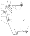
- FIG. 5 and 6 is another embodiment for an emergency release shown with decoupling.
- the Bowden cable 41 is in a Guide 42 out and attached to a mounting nipple 43.
- a Bowden cable 41 surrounding compression spring 44 is disposed against the Swivel lever 45 presses and the Bowden cable 41 tensioned.
- a second lever 46th on On the upper bolt 45a of the pivot lever 45 engages except the mounting nipple 43, a second lever 46th on, which consists of a bent 46 a and a straight portion 46 b.
- the end of the straight portion 46b is connected to a pin 47a, which with his both ends in congruent slots 47 b of a third lever 47 out is, which has a U-shaped cross-section.
- the slots 47b are located in the both side walls 47c, 47d of the lever 47.
- the one side wall 47d of the U-shaped Lever 47 has an extended portion of the axial shaft a spring-loaded rotary magnet 48 is connected.
- On the bolt 47a are between the straight portion 46b of the lever 46 and the side walls 47c, 47d of the U-shaped lever 47 each have a disc 49 arranged.
- a fourth lever 50 mounted which is designed as a pivot plate.
- the pivot plate 50 has at its front end facing towards the bolt 47a, in the lower Area an arcuate recess 50a.
- the arcuate recess 50a Limiting section is engaged with the during the unlocking process on the bolt 47a of the lever 47 arranged discs 49.
- the lower end portion the pivot plate 50 has a longitudinal slot-like Recess 50b, which is slightly larger than the wall thickness of the straight section 46b of the lever 46, allowing a safe and reliable contact between the discs 49 and the pivot plate 50 is ensured.
- the slit-like Recess 50b also serves as a guide for the straight portion 46b of the lever 46th
- each a coupling rod 52 and 53, the over corresponding deflecting units 58 ( Figure 6) with the vertical locking bars 14 are in operative connection.
- the two coupling rods 52, 53, in opposite Direction are in height and vertically offset from each other arranged.
- the articulation point for the coupling rod 53 on the pivot plate 50th is located directly above the arcuate recess 50b.
- Rod 54 is at its opposite to the pivot plate 50 with one of the end End sides of an eccentrically mounted plate 55 is connected, as shown in Fig. 6.
- the Plate 55 is pivotally mounted on a vertical shaft 56.
- a plunger 57 on In about diagonally opposite to the articulation point of the rod 54 engages the plate 55, a plunger 57 on, starting from the direction of rotation of the motor housing in a reciprocating motion is added.
- the plunger 57 transmits them Movement on the pivotable plate 55, which moves about its axis of rotation 56, whereby the rod 54 triggers the movement of the pivot plate 50 ( Figure 5).
- the operation of the emergency release is as follows.
- the two deflection units 58 consist of an angle 58 a with a horizontal shaft 58b, at the ends of each of which a lever 58c, 58d is attached.
- Lever 58c is connected via a ball joint with the locking rod 14 in Connection.
- the other lever 58d has at its upwardly facing end projecting semicircular nose, which in a corresponding recess of a further lever 58e engages rotatably on the vertical leg of the elbow 58a is mounted and with its upper end via a ball joint the respective coupling rod 52, 53 is connected.
- About the deflection units 58 is the horizontal movement of the coupling rods 52, 53 in a vertical movement of the Locking rods 14 converted.
Landscapes
- Engineering & Computer Science (AREA)
- Mechanical Engineering (AREA)
- Lock And Its Accessories (AREA)
Abstract
Description
- Fig. 1
- eine zweiflügelige Schwenkschiebetür im eingebauten und geschlossenen Zustand, als Draufsicht,
- Fig. 2
- den am Türrahmen angeordneten Ver- und Entriegelungsmechanismus mit dazugehörigem Antrieb für die Schwenkschiebetür gemäß Fig. 1, als Vorderansicht in perspektivischer Darstellung,
- Fig. 3
- die Einzelheit "X" gemäß Fig. 2 in vergrößerter Darstellung,
- Fig. 4
- Die Einzelheit "Y" gemäß Fig. 2 in vergrößerter Darstellung,
- Fig. 5
- eine weitere Ausführungsvariante der Notentriegelung mit Entkopplung als perspektivische Darstellung und
- Fig. 6
- einen für die Ausführungsvariante gemäß Fig. 5 bestimmten, am Türrahmen angeordneten Ver- und Entriegelungsmechanismus, als perspektivische Darstellung.
Claims (15)
- Notentriegelungsvorrichtung für Ver- und Entriegelungssysteme für Schwenkschiebetüren, insbesondere von Schienenfahrzeugen, bestehend aus einem an einem Hebelsystem angreifenden Zugmittel (32, 41), dadurch gekennzeichnet, dass das Zugmittel (32, 41) an einem ersten federbelasteten Schwenkhebel (33, 45) angreift, der über einen zweiten Hebel (34, 46) mit einem dritten Hebel (36, 47) verbunden ist, wobei der dritte Hebel (36,47) auf der axialen Welle (36a) eines federbelasteten Drehmagneten (37, 48) befestigt ist und Langlöcher (36c, 47b) besitzt, in denen ein Bolzen (35, 47a) verschiebbar gelagert ist, der bei einer Zugbeanspruchung des Zugmittels (32, 41) mit einem auf einer Welle (22, 51) schwenkbar gelagerten vierten Hebel (21, 50) in Eingriff gelangt und diesen bewegt, wobei der vierte Hebel (21, 50) über mindestens eine horizontal angeordnete Koppelstange (24, 25, 52, 53) und Umlenkeinheit (26, 27, 58) mit einer in vertikaler Richtung bewegbaren Verriegelungsstange (14) in Wirkungsverbindung steht und an dem vierten Hebel (21, 50) eine Stange (20, 54) angreift, über die zeitweise eine die Ver- und Entriegelung der Türblätter (1, 1a, 1b) bewirkende Kraftkomponente einleitbar ist.
- Notentriegelungsvorrichtung nach Anspruch 1, dadurch gekennzeichnet, dass der zweite Hebel (34) als gebogene Lasche ausgebildet ist, die in dem ersten Schwenkhebel (33) versetzt zu dessen Drehachse (33a) drehgelenkig gehalten ist, und an dem abstehenden Ende der Lasche (34) der Bolzen (35) in vertikaler Richtung angeordnet ist, der in Wirkungsverbindung mit dem dritten Hebel (36) steht, der eine als horizontale Führung (36b) dienende Aussparung und deckungsgleiche Langlöcher (36c) als vertikale Führung aufweist, und der vierte Hebel (21) an seinem zu dem dritten Schwenkhebel (36) zeigenden Ende eine halbkreis- oder klauenförmige Ausnehmung (21a) besitzt, die mit dem in dem zweiten Hebel (36) geführten Bolzen (35) zeitweise in Eingriff steht.
- Notentriegelungsvorrichtung nach einem der Ansprüche 1 oder 2, dadurch gekennzeichnet, dass der erste Hebel (33), der dritte Hebel (36) und der vierte Hebel (21) als Schwenkhebel ausgebildet sind, die auf einer horizontal angeordneten Platte (17) oder einem Trägerelement gelagert sind.
- Notentriegelungsvorrichtung nach einem der Ansprüche 1 bis 3, dadurch gekennzeichnet, dass an dem vierten Schwenkhebel (21), gegenüberliegend zu der Ausnehmung (21a) die Zugstange (20) zur Übertragung einer Bewegungskraft angreift.
- Notentriegelungsvorrichtung nach einem der Ansprüche 1 bis 4, dadurch gekennzeichnet, dass der vierte Schwenkhebel (21) mit einer in seiner Drehachse liegenden vertikalen Welle (22) starr verbunden ist.
- Notentriegelungsvorrichtung nach einem der Ansprüche 1 bis 5, dadurch gekennzeichnet, dass am unteren Ende der Welle (22) ein Hebel (23) befestigt ist, an dem mindestens eine Koppelstange (24, 25) zur Übertragung einer Bewegungskraft für die Ver- und Entriegelung befestigt ist.
- Notentriegelungsvorrichtung nach einem der Ansprüche 1 bis 6, dadurch gekennzeichnet, dass zur Entkopplung der Notentriegelung die die Drehhachse für den dritten Hebel (36) bildende Welle (36a) des federbelasteten Drehmagneten (37) in vertikaler Richtung angeordnet ist, wobei im spannungsbeaufschlagten Zustand des Drehmagneten (37) dieser Hebel (36) entgegen der Uhrzeigerrichtung bewegbar ist und dadurch der Bolzen (35) außer Eingriff mit der klauenförmigen Ausnehmung (21a) des vierten Schwenkhebels (21) gelangt.
- Notentriegelungsvorrichtung nach Anspruch 1, dadurch gekennzeichnet, dass im oberen Bereich des Türrahmens eine Halterung (40) angeordnet ist, die eine Führung (42) besitzt, in der das Zugmittel (41) unter Spannung durch eine Feder (44) gehalten ist, wobei der erste Schwenkhebel (45) beabstandet zu der Führung (42) als bügelartiger Hebel (45) ausgebildet ist, der an der Halterung (40) schwenkbar gelagert ist und dessen Arme am oberen Ende durch einen Bolzen (45a) verbunden sind, an dem das Zugmittel (41) und der zweite Hebel (46) angreifen.
- Notentriegelungsvorrichtung nach einem der Ansprüche 1 oder 8, dadurch gekennzeichnet, dass der zweite Hebel (46) aus einem gebogenen Teilstück (46a) und einem geraden Teilstück (46b) besteht, wobei das obere Ende des gebogenen Teilstückes (46a) mit dem Bolzen (45a) verbunden ist und das Ende des geraden Teilstückes (46b) mittig an dem Bolzen (47a) des dritten Hebels (47) gelagert ist.
- Notentriegelungsvorrichtung nach einem der Ansprüche 1 oder 8 bis 9, dadurch gekennzeichnet, dass der dritte Hebel (47) als U-förmiger Hebel ausgebildet ist, in dessen Seitenwänden (47c, 47d) sich die Langlöcher (47b) befinden und die hintere Seitenwand (47d) einen verlängerten Abschnitt besitzt, der mit der axialen Welle des Drehmagneten (48) verbunden ist, die horizontal angeordnet ist.
- Notentriegelungsvorrichtung nach einem der Ansprüche 1 oder 8 bis 10, dadurch gekennzeichnet, dass der vierte Hebel als Schwenkplatte (50) ausgebildet ist, die an einer im oberen Bereich des Türrahmens angeordneten Montageplatte auf einer horizontal angeordneten Welle (51) gelagert ist, wobei die Schwenkplatte (50) im unteren Bereich, stirnseitig eine bogenförmige Ausnehmung (50a) besitzt, und am unteren Ende eine in Längsrichtung verlaufende schlitzförmige Aussparung (50b), in das gerade Teilstück (46b) des Hebels (46) zumindest zeitweise eingreift.
- Notentriegelungsvorrichtung nach einem der Ansprüche 1 oder 8 bis 11, dadurch gekennzeichnet, dass benachbart zu dem geraden Teilstück (46b) des Hebels (46) auf dem Bolzen (47a) jeweils eine Scheibe (49) angeordnet ist, die bei Zugbeanspruchung des Zugmittels (41) in Eingriff mit dem die bogenförmige Ausnehmung (50a) begrenzenden Abschnitt gelangen.
- Notentriegelungsvorrichtung nach einem der Ansprüche 1 oder 8 bis 12, dadurch gekennzeichnet, dass an der Schwenkplatte (50) im oberen Bereich und im unteren Bereich jeweils vertikal versetzt zueinander eine Koppelstange (52, 53) angreift, wobei die in entgegengesetzter Richtung horizontal verlaufenden Koppelstangen (52, 53) über Umlenkeinheiten (58) im Bereich der vertikalen Schließkanten mit den vertikal bewegbaren Verriegelungsstangen (14) in Wirkungsverbindung stehen.
- Notentriegelungsvorrichtung nach einem der Ansprüche 1 oder 8 bis 13, dadurch gekennzeichnet, dass die Stange (54) unmittelbar gegenüberliegend zum Anlenkungspunkt der Koppelstange (53) an der Schwenkplatte (50) angreift und mit ihrem anderen Ende an einer der Stirnseiten einer Platte (55) angreift, die exzentrisch an einer vertikalen Welle (56) drehbar gelagert ist, und an einer anderen Stirnseite der Platte (55) ein Stößel (57) angreift, der mit dem drehbaren Gehäuse des Motors in Verbindung steht.
- Notentriegelungsvorrichtung nach einem der Ansprüche 1 oder 8 bis 14, dadurch gekennzeichnet, dass zur Entkopplung der Notentriegelung die Stromzuführung für den federbelastete Drehmagneten (48) mit Spannung beaufschlagt ist, und der mit der axialen Welle des Drehmagneten (48) verbundene U-förmige Hebel (47) in Uhrzeigerrichtung schwenkt und dadurch der Bolzen (47a) mit den Scheiben (49) außer Eingriff mit der bogenförmigen Ausnehmung (50b) der Schwenkplatte (50) gelangt.
Applications Claiming Priority (4)
| Application Number | Priority Date | Filing Date | Title |
|---|---|---|---|
| DE10343358 | 2003-09-14 | ||
| DE10343360A DE10343360A1 (de) | 2003-09-14 | 2003-09-14 | Ver- und Entriegelungsvorrichtung für Fahrzeugtüren, insbesondere Schwenkschiebetüren für Schienenfahrzeuge |
| DE2003143358 DE10343358A1 (de) | 2003-09-14 | 2003-09-14 | Notentriegelungsvorrichtung für Ver- und Entriegelungssysteme für Schwenkschiebetüren, insbesondere von Schienenfahrzeugen |
| DE10343360 | 2003-09-14 |
Publications (2)
| Publication Number | Publication Date |
|---|---|
| EP1516984A2 true EP1516984A2 (de) | 2005-03-23 |
| EP1516984A3 EP1516984A3 (de) | 2008-01-23 |
Family
ID=34195759
Family Applications (1)
| Application Number | Title | Priority Date | Filing Date |
|---|---|---|---|
| EP04021678A Withdrawn EP1516984A3 (de) | 2003-09-14 | 2004-09-13 | Notentriegelungsvorrichtung für Ver- und Entriegelungssysteme für Schwenkschiebetüren, insbesondere für Schienenfahrzeuge |
Country Status (1)
| Country | Link |
|---|---|
| EP (1) | EP1516984A3 (de) |
Cited By (15)
| Publication number | Priority date | Publication date | Assignee | Title |
|---|---|---|---|---|
| DE202005015169U1 (de) * | 2005-09-27 | 2007-02-15 | Gebr. Bode Gmbh & Co. Kg | Schwenkschiebetür für Fahrzeuge, insbesondere Fahrgasttür für Fahrzeuge des öffentlichen Personennahverkehrs |
| DE202005015166U1 (de) * | 2005-09-27 | 2007-02-15 | Gebr. Bode Gmbh & Co. Kg | Schwenkschiebetür für Fahrzeuge, insbesondere Fahrgasttür für Fahrzeuge des öffentlichen Personennahverkehrs |
| WO2015039159A1 (de) * | 2013-09-23 | 2015-03-26 | Knorr-Bremse Gesellschaft Mit Beschränkter Haftung | Schiebetürmodul/schwenkschiebetürmodul mit fliegender lagerung einer zahnstange eines zahnstangenantriebs |
| EP2860080A3 (de) * | 2013-09-23 | 2015-07-08 | Knorr-Bremse Gesellschaft mit beschränkter Haftung | Materialpaarung für einen Zahnstangenantrieb eines Schiebetürmoduls/Schwenkschiebetürmoduls |
| WO2016008933A1 (de) * | 2014-07-16 | 2016-01-21 | Siemens Ag Österreich | Verriegelungssystem |
| CN106761134A (zh) * | 2016-12-28 | 2017-05-31 | 华中科技大学 | 一种差速运动的电动双扇内摆门系统 |
| WO2017191330A1 (de) * | 2016-05-02 | 2017-11-09 | Gebr. Bode Gmbh & Co. Kg | Umlenkwippe zur betätigung einer drehfalle einer fahrzeugschiebetür |
| EP2899089B1 (de) | 2013-09-23 | 2019-11-06 | Knorr-Bremse Gesellschaft mit beschränkter Haftung | Schwenkschiebetürmodul für ein Schienenfahrzeug mit mehreren über einen Bowdenzug gekoppelten Übertotpunktverriegelungen |
| CN110552592A (zh) * | 2018-05-31 | 2019-12-10 | 北京天乐泰力科技发展有限公司 | 塞拉门 |
| CN110552561A (zh) * | 2019-10-11 | 2019-12-10 | 无锡市东舟船舶设备股份有限公司 | 防火a60移门推杆连接释放装置 |
| WO2020239489A1 (de) * | 2019-05-31 | 2020-12-03 | Knorr-Bremse Gesellschaft Mit Beschränkter Haftung | Fahrzeugtürvorrichtung mit stromloser öffnungsfunktion |
| CN112796591A (zh) * | 2021-01-23 | 2021-05-14 | 李虹 | 一种轨道交通应急门锁机构 |
| WO2021121873A1 (de) * | 2019-12-19 | 2021-06-24 | Siemens Mobility GmbH | Schliesssystem mit notentriegelung für ein transportmittel sowie verfahren zur steuerung der notentriegelung |
| US20220112748A1 (en) * | 2019-02-01 | 2022-04-14 | Christian Guillemette | Multipoint door lock system |
| RU2776759C1 (ru) * | 2019-05-31 | 2022-07-26 | Кнорр-Бремзе Гезелльшафт Мит Бешренктер Хафтунг | Дверное устройство транспортного средства с функцией аварийного открывания без подачи тока |
Citations (6)
| Publication number | Priority date | Publication date | Assignee | Title |
|---|---|---|---|---|
| EP0197025A1 (de) | 1985-03-26 | 1986-10-08 | IFE Industrie-Einrichtungen Fertigungs-Aktiengesellschaft | Notbetätigungseinrichtung für grifflose Türverriegelungen |
| DE3808390A1 (de) | 1987-04-02 | 1988-10-20 | Simmering Graz Pauker Ag | Tuerverriegelung fuer fahrzeuge, insbesondere fuer waggons mit schwenkschiebetueren |
| EP0335860A1 (de) | 1988-03-29 | 1989-10-04 | IFE Industrie-Einrichtungen Fertigungs-Aktiengesellschaft | Notbetätigungsvorrichtung für eine mittels eines nicht selbsthemmenden elektrischen Antriebes betätigte Fahrzeugtüre |
| EP1072749A2 (de) | 1999-06-15 | 2001-01-31 | Gebrüder Bode GmbH & Co.KG | Elektromechanischer Antrieb für eine Drehsäule zur Bewegung eines Türflügels einer Innenschwenk- oder Aussenschwingtür an einem Fahrzeug, insbesondere einem öffentlichen Verkehrsmittel |
| DE19745753C2 (de) | 1997-10-16 | 2001-02-15 | Webasto Tuersysteme Gmbh | Notentriegelungssystem für eine fremdkraftbetätigte Fahrzeugtür |
| DE10116583A1 (de) | 2001-04-03 | 2002-10-17 | Fahrzeugtechnik Dessau Gmbh Ra | Ver- und Entriegelungsvorrichtung für Fahrzeugtüren, insbesondere Schwenkschiebetüren für Schienenfahrzeuge |
Family Cites Families (3)
| Publication number | Priority date | Publication date | Assignee | Title |
|---|---|---|---|---|
| AT387619B (de) * | 1986-03-24 | 1989-02-27 | Ife Gmbh | Antriebsvorrichtung fuer tueren, insbesondere fuer fahrzeugtueren |
| DE4133179A1 (de) * | 1991-10-07 | 1993-04-08 | Bode & Co Geb | Vorrichtung zur bewegung einer schwenkschiebetuer fuer fahrzeuge zur personenbefoerderung, insbesondere schienenfahrzeuge |
| GB2285476B (en) * | 1994-01-11 | 1997-09-24 | Rockwell Body & Chassis Syst | Vehicle door lock actuator |
-
2004
- 2004-09-13 EP EP04021678A patent/EP1516984A3/de not_active Withdrawn
Patent Citations (6)
| Publication number | Priority date | Publication date | Assignee | Title |
|---|---|---|---|---|
| EP0197025A1 (de) | 1985-03-26 | 1986-10-08 | IFE Industrie-Einrichtungen Fertigungs-Aktiengesellschaft | Notbetätigungseinrichtung für grifflose Türverriegelungen |
| DE3808390A1 (de) | 1987-04-02 | 1988-10-20 | Simmering Graz Pauker Ag | Tuerverriegelung fuer fahrzeuge, insbesondere fuer waggons mit schwenkschiebetueren |
| EP0335860A1 (de) | 1988-03-29 | 1989-10-04 | IFE Industrie-Einrichtungen Fertigungs-Aktiengesellschaft | Notbetätigungsvorrichtung für eine mittels eines nicht selbsthemmenden elektrischen Antriebes betätigte Fahrzeugtüre |
| DE19745753C2 (de) | 1997-10-16 | 2001-02-15 | Webasto Tuersysteme Gmbh | Notentriegelungssystem für eine fremdkraftbetätigte Fahrzeugtür |
| EP1072749A2 (de) | 1999-06-15 | 2001-01-31 | Gebrüder Bode GmbH & Co.KG | Elektromechanischer Antrieb für eine Drehsäule zur Bewegung eines Türflügels einer Innenschwenk- oder Aussenschwingtür an einem Fahrzeug, insbesondere einem öffentlichen Verkehrsmittel |
| DE10116583A1 (de) | 2001-04-03 | 2002-10-17 | Fahrzeugtechnik Dessau Gmbh Ra | Ver- und Entriegelungsvorrichtung für Fahrzeugtüren, insbesondere Schwenkschiebetüren für Schienenfahrzeuge |
Cited By (25)
| Publication number | Priority date | Publication date | Assignee | Title |
|---|---|---|---|---|
| DE202005015169U1 (de) * | 2005-09-27 | 2007-02-15 | Gebr. Bode Gmbh & Co. Kg | Schwenkschiebetür für Fahrzeuge, insbesondere Fahrgasttür für Fahrzeuge des öffentlichen Personennahverkehrs |
| DE202005015166U1 (de) * | 2005-09-27 | 2007-02-15 | Gebr. Bode Gmbh & Co. Kg | Schwenkschiebetür für Fahrzeuge, insbesondere Fahrgasttür für Fahrzeuge des öffentlichen Personennahverkehrs |
| WO2015039159A1 (de) * | 2013-09-23 | 2015-03-26 | Knorr-Bremse Gesellschaft Mit Beschränkter Haftung | Schiebetürmodul/schwenkschiebetürmodul mit fliegender lagerung einer zahnstange eines zahnstangenantriebs |
| EP2860080A3 (de) * | 2013-09-23 | 2015-07-08 | Knorr-Bremse Gesellschaft mit beschränkter Haftung | Materialpaarung für einen Zahnstangenantrieb eines Schiebetürmoduls/Schwenkschiebetürmoduls |
| AU2014324064B2 (en) * | 2013-09-23 | 2017-10-19 | Knorr-Bremse Gesellschaft Mit Beschrankter Haftung | Sliding door module/pivoting sliding door module having floating mounting of a rack of a rack-and-pinion drive |
| RU2640665C2 (ru) * | 2013-09-23 | 2018-01-11 | Кнорр-Бремзе Гезелльшафт Мит Бешренктер Хафтунг | Модуль раздвижной двери/поворотно-раздвижной двери с консольным креплением зубчатой рейки реечного привода |
| US9874050B2 (en) | 2013-09-23 | 2018-01-23 | Knorr-Bremse Gesellschaft Mit Beschrankter Haftung | Sliding door module/pivoting sliding door module having floating mounting of a rack of a rack-and-pinion drive |
| EP2899089B1 (de) | 2013-09-23 | 2019-11-06 | Knorr-Bremse Gesellschaft mit beschränkter Haftung | Schwenkschiebetürmodul für ein Schienenfahrzeug mit mehreren über einen Bowdenzug gekoppelten Übertotpunktverriegelungen |
| WO2016008933A1 (de) * | 2014-07-16 | 2016-01-21 | Siemens Ag Österreich | Verriegelungssystem |
| WO2017191330A1 (de) * | 2016-05-02 | 2017-11-09 | Gebr. Bode Gmbh & Co. Kg | Umlenkwippe zur betätigung einer drehfalle einer fahrzeugschiebetür |
| WO2017198254A1 (de) * | 2016-05-02 | 2017-11-23 | Gebr. Bode Gmbh & Co. Kg | Umlenkwippe zur betätigung einer drehfalle einer fahrzeugschiebetür |
| CN106761134A (zh) * | 2016-12-28 | 2017-05-31 | 华中科技大学 | 一种差速运动的电动双扇内摆门系统 |
| CN110552592A (zh) * | 2018-05-31 | 2019-12-10 | 北京天乐泰力科技发展有限公司 | 塞拉门 |
| US20220112748A1 (en) * | 2019-02-01 | 2022-04-14 | Christian Guillemette | Multipoint door lock system |
| US11473352B2 (en) * | 2019-02-01 | 2022-10-18 | Christian Guillemette | Multipoint door lock system |
| WO2020239489A1 (de) * | 2019-05-31 | 2020-12-03 | Knorr-Bremse Gesellschaft Mit Beschränkter Haftung | Fahrzeugtürvorrichtung mit stromloser öffnungsfunktion |
| CN113891977A (zh) * | 2019-05-31 | 2022-01-04 | 克诺尔有限公司 | 具有无电流打开功能的车门装置 |
| RU2776759C1 (ru) * | 2019-05-31 | 2022-07-26 | Кнорр-Бремзе Гезелльшафт Мит Бешренктер Хафтунг | Дверное устройство транспортного средства с функцией аварийного открывания без подачи тока |
| CN113891977B (zh) * | 2019-05-31 | 2022-08-30 | 克诺尔有限公司 | 具有无电流打开功能的车门装置 |
| US12044054B2 (en) | 2019-05-31 | 2024-07-23 | Knorr-Bremse Gesellschaft Mit Beschränkter Haftung | Vehicle door device with a currentless opening function |
| CN110552561A (zh) * | 2019-10-11 | 2019-12-10 | 无锡市东舟船舶设备股份有限公司 | 防火a60移门推杆连接释放装置 |
| CN110552561B (zh) * | 2019-10-11 | 2024-04-05 | 无锡市东舟船舶设备股份有限公司 | 防火a60移门推杆连接释放装置 |
| WO2021121873A1 (de) * | 2019-12-19 | 2021-06-24 | Siemens Mobility GmbH | Schliesssystem mit notentriegelung für ein transportmittel sowie verfahren zur steuerung der notentriegelung |
| CN112796591A (zh) * | 2021-01-23 | 2021-05-14 | 李虹 | 一种轨道交通应急门锁机构 |
| RU2784881C2 (ru) * | 2021-05-06 | 2022-11-30 | Общество с ограниченной ответственностью "Производственная компания "Дверные системы" | Устройство привода двухстворчатой двери |
Also Published As
| Publication number | Publication date |
|---|---|
| EP1516984A3 (de) | 2008-01-23 |
Similar Documents
| Publication | Publication Date | Title |
|---|---|---|
| EP1584535B1 (de) | Schwenkschiebetür für Schienenfahrzeuge | |
| EP1541517A1 (de) | Einrichtung an einer Aufzugskabine zum temporären Koppeln eines Kabinentürflügels mit einem Schachttürflügel und zum Betätigen einer Kabinentürverrieglung | |
| DE10041498B4 (de) | Schließeinrichtung für eine Fahrzeugtür | |
| EP1516984A2 (de) | Notentriegelungsvorrichtung für Ver- und Entriegelungssysteme für Schwenkschiebetüren, insbesondere für Schienenfahrzeuge | |
| EP1767427B1 (de) | Einrichtung zur Bewegung des Türblattes einer Schwenkschiebetür, insbesondere für Schienenfahrzeuge | |
| EP1767388A2 (de) | Schwenkschiebetür für Fahrzeuge, insbesondere Fahrgasttür für Fahrzeuge des offentlichen Personnenverkehrs | |
| DE202005015166U1 (de) | Schwenkschiebetür für Fahrzeuge, insbesondere Fahrgasttür für Fahrzeuge des öffentlichen Personennahverkehrs | |
| EP2165868B1 (de) | Schwenkschiebetürsystem | |
| DE10105771B4 (de) | Verschlußvorrichtung für ein Cabriolet-Verdeck | |
| EP1514985A2 (de) | Ver- und Entriegelungsvorrichtung für Fahrzeugtüren insbesondere Schwenkschiebetüren für Schienenfahrzeuge | |
| EP0743416A1 (de) | Antriebseinrichtung für ein Torblatt | |
| DE10116580A1 (de) | Schwenkschiebetür für Schienenfahrzeuge | |
| EP1488977B1 (de) | Ausstellschiebetürsystem für ein Fahrzeug | |
| EP1813759B1 (de) | Vorrichtung zum Bewegen einer Schwenkschiebetür eines Kraftfahrzeugs | |
| EP1826342B1 (de) | Sektionaltor mit Fluchttür | |
| DE3026037C2 (de) | Fahrzeugtür mit Schwenk- und Schiebebewegung | |
| DE102004047166B4 (de) | Sektionaltor mit Fluchttür | |
| DE10116583A1 (de) | Ver- und Entriegelungsvorrichtung für Fahrzeugtüren, insbesondere Schwenkschiebetüren für Schienenfahrzeuge | |
| DE102020111221A1 (de) | Laufwagenanordnung für eine Schiebetür | |
| DE202007013330U1 (de) | Kraftfahrzeugschloß | |
| DE10343359A1 (de) | Ver- und Entriegelungsvorrichtung für zweiflügelige Fahrzeugtüren, insbesondere Schwenkschiebetüren für Schienenfahrzeuge | |
| DE10343361A1 (de) | Schwenkschiebetür für Schienenfahrzeuge | |
| EP4249715B1 (de) | Vorrichtung zur verriegelung eines türflügels | |
| EP0518099B1 (de) | Vorrichtung zum Öffnen und Schliessen von Kipptoren | |
| EP4019364B1 (de) | Schwenkschiebetür |
Legal Events
| Date | Code | Title | Description |
|---|---|---|---|
| PUAI | Public reference made under article 153(3) epc to a published international application that has entered the european phase |
Free format text: ORIGINAL CODE: 0009012 |
|
| AK | Designated contracting states |
Kind code of ref document: A2 Designated state(s): AT BE BG CH CY CZ DE DK EE ES FI FR GB GR HU IE IT LI LU MC NL PL PT RO SE SI SK TR |
|
| AX | Request for extension of the european patent |
Extension state: AL HR LT LV MK |
|
| PUAL | Search report despatched |
Free format text: ORIGINAL CODE: 0009013 |
|
| AK | Designated contracting states |
Kind code of ref document: A3 Designated state(s): AT BE BG CH CY CZ DE DK EE ES FI FR GB GR HU IE IT LI LU MC NL PL PT RO SE SI SK TR |
|
| AX | Request for extension of the european patent |
Extension state: AL HR LT LV MK |
|
| 17P | Request for examination filed |
Effective date: 20080319 |
|
| AKX | Designation fees paid |
Designated state(s): AT CH DE FR IT LI |
|
| AXX | Extension fees paid |
Extension state: HR Payment date: 20080319 |
|
| 17Q | First examination report despatched |
Effective date: 20090519 |
|
| RAP1 | Party data changed (applicant data changed or rights of an application transferred) |
Owner name: FTD FAHRZEUGTECHNIK DESSAU GMBH CTF |
|
| GRAP | Despatch of communication of intention to grant a patent |
Free format text: ORIGINAL CODE: EPIDOSNIGR1 |
|
| STAA | Information on the status of an ep patent application or granted ep patent |
Free format text: STATUS: THE APPLICATION IS DEEMED TO BE WITHDRAWN |
|
| 18D | Application deemed to be withdrawn |
Effective date: 20110503 |