EP1516996A2 - Sprengwirkungshemmendes Fenster - Google Patents
Sprengwirkungshemmendes Fenster Download PDFInfo
- Publication number
- EP1516996A2 EP1516996A2 EP04022051A EP04022051A EP1516996A2 EP 1516996 A2 EP1516996 A2 EP 1516996A2 EP 04022051 A EP04022051 A EP 04022051A EP 04022051 A EP04022051 A EP 04022051A EP 1516996 A2 EP1516996 A2 EP 1516996A2
- Authority
- EP
- European Patent Office
- Prior art keywords
- window
- frame
- sash
- hinges
- tilting
- Prior art date
- Legal status (The legal status is an assumption and is not a legal conclusion. Google has not performed a legal analysis and makes no representation as to the accuracy of the status listed.)
- Granted
Links
- 238000004880 explosion Methods 0.000 title abstract description 7
- 230000000694 effects Effects 0.000 claims abstract description 16
- 238000006073 displacement reaction Methods 0.000 claims description 29
- 239000002360 explosive Substances 0.000 claims description 17
- 238000012423 maintenance Methods 0.000 claims description 15
- 239000011521 glass Substances 0.000 claims description 5
- 238000004873 anchoring Methods 0.000 claims description 2
- 239000013536 elastomeric material Substances 0.000 claims description 2
- 238000009423 ventilation Methods 0.000 abstract description 5
- 238000005474 detonation Methods 0.000 description 8
- 229910000831 Steel Inorganic materials 0.000 description 5
- 238000010276 construction Methods 0.000 description 5
- 239000010959 steel Substances 0.000 description 5
- 238000004140 cleaning Methods 0.000 description 3
- 238000004519 manufacturing process Methods 0.000 description 3
- 230000008901 benefit Effects 0.000 description 2
- 230000015572 biosynthetic process Effects 0.000 description 2
- 230000006378 damage Effects 0.000 description 2
- 230000002787 reinforcement Effects 0.000 description 2
- 239000007787 solid Substances 0.000 description 2
- 229910001220 stainless steel Inorganic materials 0.000 description 2
- 239000010935 stainless steel Substances 0.000 description 2
- 229910000760 Hardened steel Inorganic materials 0.000 description 1
- 229910001315 Tool steel Inorganic materials 0.000 description 1
- 208000027418 Wounds and injury Diseases 0.000 description 1
- 230000005540 biological transmission Effects 0.000 description 1
- 230000009172 bursting Effects 0.000 description 1
- 230000006835 compression Effects 0.000 description 1
- 238000007906 compression Methods 0.000 description 1
- 238000009826 distribution Methods 0.000 description 1
- 230000009931 harmful effect Effects 0.000 description 1
- 231100001261 hazardous Toxicity 0.000 description 1
- 208000014674 injury Diseases 0.000 description 1
- 239000000463 material Substances 0.000 description 1
- 239000011159 matrix material Substances 0.000 description 1
- 230000000116 mitigating effect Effects 0.000 description 1
- 238000003825 pressing Methods 0.000 description 1
- 230000003014 reinforcing effect Effects 0.000 description 1
- 238000003860 storage Methods 0.000 description 1
- 238000003466 welding Methods 0.000 description 1
Images


Classifications
-
- E—FIXED CONSTRUCTIONS
- E06—DOORS, WINDOWS, SHUTTERS, OR ROLLER BLINDS IN GENERAL; LADDERS
- E06B—FIXED OR MOVABLE CLOSURES FOR OPENINGS IN BUILDINGS, VEHICLES, FENCES OR LIKE ENCLOSURES IN GENERAL, e.g. DOORS, WINDOWS, BLINDS, GATES
- E06B3/00—Window sashes, door leaves, or like elements for closing wall or like openings; Layout of fixed or moving closures, e.g. windows in wall or like openings; Features of rigidly-mounted outer frames relating to the mounting of wing frames
- E06B3/32—Arrangements of wings characterised by the manner of movement; Arrangements of movable wings in openings; Features of wings or frames relating solely to the manner of movement of the wing
- E06B3/34—Arrangements of wings characterised by the manner of movement; Arrangements of movable wings in openings; Features of wings or frames relating solely to the manner of movement of the wing with only one kind of movement
- E06B3/341—Tilt-and-turn wings
-
- E—FIXED CONSTRUCTIONS
- E05—LOCKS; KEYS; WINDOW OR DOOR FITTINGS; SAFES
- E05D—HINGES OR SUSPENSION DEVICES FOR DOORS, WINDOWS OR WINGS
- E05D15/00—Suspension arrangements for wings
- E05D15/48—Suspension arrangements for wings allowing alternative movements
- E05D15/52—Suspension arrangements for wings allowing alternative movements for opening about a vertical as well as a horizontal axis
- E05D15/5205—Suspension arrangements for wings allowing alternative movements for opening about a vertical as well as a horizontal axis with horizontally-extending checks
-
- E—FIXED CONSTRUCTIONS
- E05—LOCKS; KEYS; WINDOW OR DOOR FITTINGS; SAFES
- E05D—HINGES OR SUSPENSION DEVICES FOR DOORS, WINDOWS OR WINGS
- E05D15/00—Suspension arrangements for wings
- E05D15/48—Suspension arrangements for wings allowing alternative movements
- E05D15/52—Suspension arrangements for wings allowing alternative movements for opening about a vertical as well as a horizontal axis
- E05D15/5217—Tilt-lock devices
-
- E—FIXED CONSTRUCTIONS
- E06—DOORS, WINDOWS, SHUTTERS, OR ROLLER BLINDS IN GENERAL; LADDERS
- E06B—FIXED OR MOVABLE CLOSURES FOR OPENINGS IN BUILDINGS, VEHICLES, FENCES OR LIKE ENCLOSURES IN GENERAL, e.g. DOORS, WINDOWS, BLINDS, GATES
- E06B3/00—Window sashes, door leaves, or like elements for closing wall or like openings; Layout of fixed or moving closures, e.g. windows in wall or like openings; Features of rigidly-mounted outer frames relating to the mounting of wing frames
- E06B3/32—Arrangements of wings characterised by the manner of movement; Arrangements of movable wings in openings; Features of wings or frames relating solely to the manner of movement of the wing
- E06B3/34—Arrangements of wings characterised by the manner of movement; Arrangements of movable wings in openings; Features of wings or frames relating solely to the manner of movement of the wing with only one kind of movement
- E06B3/38—Arrangements of wings characterised by the manner of movement; Arrangements of movable wings in openings; Features of wings or frames relating solely to the manner of movement of the wing with only one kind of movement with a horizontal axis of rotation at the top or bottom of the opening
-
- E—FIXED CONSTRUCTIONS
- E06—DOORS, WINDOWS, SHUTTERS, OR ROLLER BLINDS IN GENERAL; LADDERS
- E06B—FIXED OR MOVABLE CLOSURES FOR OPENINGS IN BUILDINGS, VEHICLES, FENCES OR LIKE ENCLOSURES IN GENERAL, e.g. DOORS, WINDOWS, BLINDS, GATES
- E06B5/00—Doors, windows, or like closures for special purposes; Border constructions therefor
- E06B5/10—Doors, windows, or like closures for special purposes; Border constructions therefor for protection against air-raid or other war-like action; for other protective purposes
- E06B5/12—Doors, windows, or like closures for special purposes; Border constructions therefor for protection against air-raid or other war-like action; for other protective purposes against air pressure, explosion, or gas
- E06B5/125—Closures for relieving excess pressure inside the building
-
- E—FIXED CONSTRUCTIONS
- E05—LOCKS; KEYS; WINDOW OR DOOR FITTINGS; SAFES
- E05Y—INDEXING SCHEME ASSOCIATED WITH SUBCLASSES E05D AND E05F, RELATING TO CONSTRUCTION ELEMENTS, ELECTRIC CONTROL, POWER SUPPLY, POWER SIGNAL OR TRANSMISSION, USER INTERFACES, MOUNTING OR COUPLING, DETAILS, ACCESSORIES, AUXILIARY OPERATIONS NOT OTHERWISE PROVIDED FOR, APPLICATION THEREOF
- E05Y2900/00—Application of doors, windows, wings or fittings thereof
- E05Y2900/10—Application of doors, windows, wings or fittings thereof for buildings or parts thereof
- E05Y2900/13—Type of wing
- E05Y2900/148—Windows
Definitions
- the invention relates to a blast resistant window with a frame and a sash, which receives a filling and in hinges on the frame around at least one axis is tiltably mounted, wherein the sash in a closed position rests in the frame.
- a window of the type described above is known for example from DE 34 20 883 C2 and known from DE 34 32 021 C2.
- the two previously known window constructions are as so formed double window. It is located in front of the actual window, the has a frame and a rotatably mounted wing frame, another Fixed glazing. Consist between the fixed glazing and the window reveal Connecting cross sections to the space between the two glazings and the Window reveal, so that in the case where the sash of the inner glazing is open, some air circulation through the double glazing take place can.
- the double glazing has the task, the effect of a detonation on the outside To mitigate the building so that people in the building as possible not to be harmed.
- a disadvantage of the prior art window construction is to be considered that on the one hand due to the two glazings, the production costs are comparatively high.
- one of the outer, in the detonation case usually destroyed glazing then not one incalculable risk to the persons inside the building if the Sash frame of the inner glazing is in its open position. In this case namely, broken glass can enter the interior of the room through the open sash, causing a considerable risk of injury.
- a sufficiently large security of the persons in the room is therefore in the Basically, only given when the sash of the inner glazing in its closed position.
- the invention is based on the object, a blast-resistant trained To propose windows in which no external front glazing is required and the nevertheless - with sufficient security for explosives attacks - in the opening position of the sash frame as needed permanent ventilation function can fulfill.
- the filling is made of bulletproof glass and that the window is at least one Kippbegrenzungselement, by means of which an induced by an explosive effect tilting the sash in the hinges beyond a Kippgrenz ein is inhibited, and at least one displacement limiting element, by means of which a by the explosive effect induced displacement of the sash perpendicular to a tilt axis in the hinges is inhibited.
- the invention is based on the finding that, contrary to the previous doctrine as well as against actual practice based on decades of practice tilted compared to a rigidly closed window by no means a principle incalculable security risk in the face of an explosive effect.
- standard windows essentially have respect to blast resistance
- the sash frame can be torn out of the frame as a whole, because the fasteners on a standard window - hinges and these opposite arranged safety shears - not for a substantial over the weight of the Wing frame with filling and a normal wind load going out load designed are. Break the fasteners under the explosive effect simultaneously, then the Sash substantially unchanged in horizontal direction in the driven adjacent room. Tear the sash clearer sooner or later Hinges as from the safety scissors, so the sash in addition to a Offset rotational movement.
- the window according to the invention inhibits an explosive effect in the same way as the well-known double windows, on the other hand, those with an internal Standard windows effectively avoided risks.
- the particular advantage of the window according to the invention is that this despite his Safety against an explosive effect for airing be brought into a tilted position can, whereas in known windows each opening position of the window a incalculable risk meant.
- Kippbegrenzungselement invention should not be understood as a standard ⁇ Stammsbegrenzungsschiene, at conventional non-safety windows are used and the Explosive explosions would not withstand forces occurring.
- Sliding limiting element not a standard pin-shaped To understand locking element, as is the case with conventional non-safety windows the fitting push rod is coupled and in frame-locking locking pockets intervenes.
- the hinges are reinforced on a window according to the invention and thereby designed as a displacement limiting elements.
- a window By using over one Standard window reinforced hinges will tear out the sash from the Frame is avoided up to a selectable amount.
- For reinforcement can on the one hand a compared to the usual tool steel as moderer material, such as a high-strength steel are used.
- the number of along the Tilting axis arranged hinges are increased.
- the window according to the invention has at least one Displacement limiting element, which on a side opposite the hinges the sash is arranged and by means of which from the Kippgrenz ein and from each Position between this and the closed position induced by the explosive effect Moving the sash in a plane of the filling perpendicular to the tilt axis is inhibited by the fact that the sash formed on a circular segment Stops stop on the displacement limiting element.
- Displacement limiting element which on a side opposite the hinges the sash is arranged and by means of which from the Kippgrenz ein and from each Position between this and the closed position induced by the explosive effect Moving the sash in a plane of the filling perpendicular to the tilt axis is inhibited by the fact that the sash formed on a circular segment Stops stop on the displacement limiting element.
- At least one two-part Displacement limiting element which is arranged in the tilting axis, and one with the Frame connected template and a patrix connected to the sash wherein the matrix and the male part have hook-shaped locking elements, wherein in the tilt limit position and in any position between this and the closed position the displacement is inhibited by the fact that the die and patrix trained Locking elements engage in each other.
- Sliding limiting elements and their design is always included Burglar-resistant windows known.
- a blast resistance to These can, in turn, be reinforced as described above for the hinges be educated.
- Such a displacement limiting element in turn allows the first Use the sash and frame of a standard window when die and male be dimensioned so that they are in an existing gap between wing and Frame can be arranged.
- the effect of each element can ever be amplified according to the application and to be secured explosive effect.
- the male of such a displacement element with a on the Wing frame connected to a window attached push rod and connected with this along the tilt axis so far displaced that the locking elements not intervene more in each other.
- push rods is basically of Standard windows known, in addition to the tilt function, a pan of the Wing frame to allow an axis perpendicular to the tilt axis. So can one Window according to the invention can be designed as a combined turn-tilt window.
- a window according to the invention advantageously has reinforced and characterized as Kippbegrenzungselement trained safety scissors, on the one hand in the Frame and on the other hand are stored in the sash.
- Kippbegrenzungselement trained safety scissors on the one hand in the Frame and on the other hand are stored in the sash.
- At least one tilt-limiting element is preferred arranged on the side opposite the hinges of the sash, on which the Wing frame in the tilt limit position strikes.
- Such an extra Sliding limiting element initially requires no change to the hinges, and is particularly suitable for use with standard frames.
- Such Tilt limiting element can be particularly advantageous with a in the above described Way formed with a circular segment-shaped stop Shift limit element can be combined in such a way that the end of a circular segment-shaped stop rail at its end the Tilt limiting element forms.
- each such Kippbegrenzungselement is at both ends of the hinges opposite side of the sash.
- each such Kippbegrenzungselement arranged.
- Compared to a rod-shaped training essentially on the entire length of the hinges opposite side of the sash is through the formation of two individual Kippbegrenzungs institute at the corners of the support effect used the sash itself. This can be done by a reinforcing insert or a otherwise reinforced execution of this side of the sash still be improved.
- Kippbegrenzungs these can be used as Modular elements in windows according to the invention of different widths for use come.
- a window according to the invention is preferably so connected to a window reveal, in the window can be used, that the Kippbegrenzungselement between a Operating position and a maintenance position is displaceable, wherein the sash in the Maintenance position of Kippbegrenzungselements beyond the Kippgrenz ein also openable is. Is the Kippbegrenzungselement in the maintenance position, then suggests the Sash does not open on opening. The sash can then go to Maintenance purposes are opened so far that its outside - for example Cleaning the outside surface of the filling - easily accessible from the room. Of the Wing frame can then be designed so that it is in the tilt axis or in one of these vertical axis is wide openable.
- the Kippbegrenzungselement can indirectly via the (connected to the window reveal) frame or directly with the window reveal be connected.
- Such a movable Kippbegrenzungselement on a window according to the invention is preferably releasably screwed to the window reveal.
- the detachable screw connection represents the technically simplest and therefore cheapest way of training a displaceable element.
- a Window according to the invention is such Kippbegrenzungselement in a plane of Sliding frame in slotted holes so that it is in its maintenance position a greater distance from the hinges than in its operating position.
- the tilt-limiting element can be guided in a particularly rail-like manner,
- the holding function is not significantly affected in the slots.
- the sash is in the tilt limit by means of a Holding device against both a continuation of the rotational movement and against one of the movement directed towards the plane of the filling, and in the Area of the hinges of the wing frame connecting frame leg are positive locking elements between the sash and the frame present, wherein the opening angle in the tilting limit of the sash between 5 ° and 50 °.
- the window according to the invention pursues the philosophy that an explosion-resistant window can also be located in a slightly open position of the sash without glazing in the event of detonation, as long as the thus released opening cross-sections are small enough and despite the pressure wave occurring an uncontrolled further opening of the sash over the Kippgrenz ein addition is prevented.
- Kippgrenz ein should be defined by the holding device position in the context of this application, in which the sash is deflected as far as possible from its closed position.
- the opening cross-section, which is released in the tilting limit position is preferably not more than 0.2 m 2 to 0.4 m 2 .
- the holding device has a continuous support surface extending from the Frame extends to a stop surface on which the sash in the Tilting limit is applied, the support surface is parallel to the trajectory, the Front edge of the sash when moving from the closed position into the Tilt limit describes. This will tear out the sash from the Swivel joints prevented even if the sash in any Intermediate positions between the closed position and the tilt limit is located.
- the invention further ausgestaltend is provided that the holding device of a Support surface having lower bracket and one perpendicular to the plane of the filling extending upper hanger, wherein the lower bracket and upper hanger both in the area of Blendrahmens and the stop surface are connected together.
- This can be a easy to manufacture, visually appealing and very torsionally rigid construction achieved become.
- a particularly good support of the entire window construction within the Building opening is achieved in that the anchor for fixing the window frame with a cross-sectionally L-shaped angle is connected, which is parallel with a leg to a window reveal and with the other leg parallel to a viewing surface of the Building extends. This allows an adjacent to the opening edge strip of Viewing surface used for the large-scale introduction of compressive forces in the building part which minimizes the risk of local exceedances of the strength limit becomes.
- the form-fitting Closing elements are formed by two angle profiles, each with a Mounting legs are connected to the sash and to the frame, itself preferably over the entire length of the associated frame legs and extend each supported with a support leg to each other.
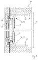
- first window 1 has a Frame 2 on which in a variety of hinges 3 (in the manner of a so-called "Piano Band", but i. d. R. consisting of individual hinges) a sash 4 by means a Kipphofflbetuschistselements 5 is tiltably mounted.
- hinges 3 in the manner of a so-called "Piano Band", but i. d. R. consisting of individual hinges
- a sash 4 by means a Kipperielbetuschistorselements 5 is tiltably mounted.
- a hinged connection of Wing frame with a frame causes while a turn, tilt or Pivoting movement of the sash around at least one axis of rotation allows.
- Sash 4 is a filling 6 made of bulletproof glass.
- FIGS. 3 of the Window 1 are compared to a standard commercial tilting window by use reinforced by hinge pin, hardened steel or stainless steel and so as Displacement limiting element 7 is formed. A tearing out of the sash 4 from the Hinges 3 and out of the frame 2 by an explosive effect is thereby effective avoided.
- Figures 1 and 2 show the window 1 in the closed position 8, in which Sash 4 rests in the frame 2.
- the tilt-limiting element 10 has an over the entire width 12 of the window reveal 13, in which the window 1 is inserted, through rod 14 and is with both sides 15th the window reveal 13 in slots 16 screwed.
- the Kippbegrenzungselement 10 After loosening each two Wing nuts 17 is the Kippbegrenzungselement 10 by means of a not shown Connecting linkage between the (solid) shown operating position 18 and the (dashed) indicated maintenance position 19 at a greater distance from the hinges. 3 manually movable.
- the window 1 according to the invention can not with one be equipped crank mechanism shown by means of which the Kippbegrenzungselement 10 from the operating position 18 in the maintenance position 19 can be transferred.
- the Kippbegrenzungselement 10 In the Maintenance position 19 is the Kippbegrenzungselement 10 also not shown Locked way and the sash 4 for maintenance - especially regularly too Cleaning purposes - tiltable beyond the tilt limit 11 addition.
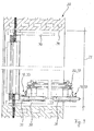
- the second window 20 according to the invention shown in FIGS. 5 to 9 differs first from the first window 1 according to FIGS. 1 to 4, in that it functions as Combined turn-tilt window executed and thus one in the installed state tilting horizontal axis or alternatively about a vertical pivot axis is pivotable.
- the window 20 has the fittings known from standard windows, Hinges and safety scissors - on. (The tilt and swivel axis and the Tilting hinges and safety shears are not shown.)
- the window 20 has in the tilting axis a plurality of across the width 21 of the Sash 22 distributed first, each in two parts Displacement limiting elements 23.
- the first displacement limiting elements 23 each consist of a frame 25 connected to the die 25 and a Patrize 26, attached to the push rod, not shown, and along with this Tilting axis is displaceable.
- the dies 25 and the patricks 26 face along the Tilting axle on a constant profile and engage with hook-shaped locking elements 27 into each other.
- the first displacement limiting elements 23 are the Frame 24 and the sash 22 in the Kippgrenz ein 28 of Figure 7 and in each intermediate position (not shown) between this and the closed state according to Figures 5, 6 and 8 firmly coupled together.
- a respective stop 30th attached, which together with a attached to the sash 22 latch 31st on the one hand as a second displacement limiting element 32 and on the other hand as Tilt limiting element 33 acts.
- the stopper 30 is formed of flat steel and with screwed to the frame 24 or with an adjacent building part. On In this way, the stop 30 is at least indirectly also with the window reveal 34th connected, in which the window 20 is inserted.
- the stopper 30 has a circular segment-shaped aperture 35 (or alternatively also a circular segment-shaped Guide rail) rail, in each of which the associated latch 31 engages.
- the the Circular segment associated - not shown - circle center is located on the tilt axis.
- the two latches 31 are formed of round steel and parallel to the tilting axis in the Wing frame 22 out.
- Levers 36 are the latch 31 parallel to the tilt axis in the manner of a drive bolt displaceable.
- the function of the lever 36 may also be an unrepresented - given case also electrically powered, covered or separately lockable - take over transmission.
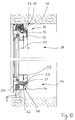
- the illustrated in Figures 10 to 13 third window 38 according to the invention has at its Top in contrast to the second window 20 according to Figures 5 to 9 no circular segment-shaped guide with stop on.
- the function of the tilt-limiting element 39 here assumes a principle known, compared to the turn-tilt fitting of a Standard window, in turn, amplified and e.g. Stainless steel safety shear 40 at the top 41 of the sash 42.
- the window 38 can also be a standard Kippbegrenzungsschere, as they are available with standard fittings have, the However, no security function takes over, but only due to the use of Standard fittings is available.
- the safety shear 40 has a mushroom-shaped pin 43, which in a parallel to the in turn, not shown tilting axis arranged, U-shaped hollow profile 44 engages.
- the hollow profile 44 is provided with a steel filling 45 fitted in the casement 42 welded and bolted to a push rod. Together with this is the hollow profile 44 slidable in the sash 42 parallel to the tilting axis.
- Such is - as of Standard windows known - the pivotal movement of the sash 42 around the vertical Rotary axis not restricted.
- the sash 42 engages with a formed on its underside 46 nose 47 in installed state under the displacement limiting element 48 and beats in the Kippgrenz ein 49 on the frame 50 at. A displacement of the sash 42 Upwards is so effectively avoided.
- a Seal member 51 is arranged, by means of which an air flow through the (naturally play) fit between the die 52 and male 53 is prevented.
- the window 38 has a compared to the standard window significantly enlarged stop depth 54, so that the lock can be transferred from the closed position to the tilted position can, so that sufficient depth for the formation of the encompassing nose 47 exists and thus over the steel filling 45 a great stability and high security against Tearing out the shear bearing exists.
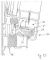
- the fourth invention shown in Figures 14 and 15 only in detail Window has, in contrast to the aforementioned third window 38 according to the figures 10th to 13 an alternatively designed displacement limiting element 55, whose with the Blendrahmen 56 connected die 57 on the in the installed state the room interior facing side 58 has an upwardly projecting nose 59.
- the sash frame 60 can in the installed state and in particular in the tilted shown in Fig. 15 Position so not be pressed into the room.
- the axially movable in the casement 60 push rod 61, with the male 62 is connected, whereas the die 57 is fixedly connected to the frame 56.
- the matrices prevent 57 / male 62 due to the lugs 59th on the matrices and the nose 47 on the casement 60 certainly both a displacement of the Sash frame 60 perpendicular to the plane of the filling into the room as well as parallel to the filling 6 perpendicular to the tilt axis.
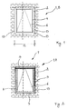
- FIG. 1 A shown in Figure 1 'without the surrounding building parts window 1' has a Frame 2 ', in which a sash 3' is movably mounted.
- a sash 3' At the sash 3 ', which has a filling 5' in the form of an insulating glass, is a tiltable skylight.
- a safety in detonations is the tilting wing by given that this by a holding device 7 'in its Kippgrenz ein (Fig. 2b') is fixed and thus only a well-defined, relatively small Opening cross-section between space and environment releases, creating an uncontrolled Pressure is prevented from outside in the room.
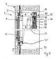
- the holding device 7' consists of an arcuate one Lower bracket 8 ', which is angled in an L-shape, and a likewise L-shaped upper bracket 9', whose vertical leg acts as a connecting strut 10 ', at the lower End an elastomeric element 11 'is arranged, which has a stop surface 12' for an upper Edge strip 13 'of the sash frame 3' forms.
- Sub-bracket 8 'and upper bracket 9' are through Welding connected with each other, so that in the result a total bow-shaped, connection-rigid holding device 7 'results. This is in the area of an end section of the Upper bracket 9 'penetrated by an anchor 14', the frame 2 'with a Building part in the form of, for example, a Hohllochziegels 15 'connects.
- the sash 3 ' is connected to a lower frame leg 16' of the frame 2 'with Help of not shown, but well-known joints in the form so-called bands 4 'stored.
- an angle profile 17 'at a lower pivot joints receiving the lower frame leg 18' of Wing frame 3 'and rotated by 180 ° arranged angle section 19' on the Frame legs 16 'of the frame 2'.
- Both angle sections 17 'and 19 'each have horizontally oriented mounting legs 22', 23 ', the on not shown in more detail, for example with the aid of screws, at sufficiently strong dimensioned parts of the frame legs 16 'and 18' are attached.
- the angle between the support leg 20 'and the mounting leg 22' of the Angle profile 17 ' is smaller than 90 °, so that the two support legs 20' and 21 'in the maximum tilting limit of the sash 3 'flat, d. H. parallel to each other running, abut each other.
- the angular difference to 90 ° corresponds to the opening angle the sash frame 3 ', as it is limited by the stop surface 12'.
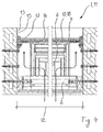
- FIG. 3 ' An upper part of the wing frame 3 'released in its tilt limit position, above rectangular and laterally wedge-shaped opening cross-section is with a Perforated plate 24 'covered. This is evident in particular from FIG. 3 '.
- the perforated plate 24 ' has two folded narrow side edge strips 25 'and a folded longitudinal side Edge strip 26 ', the upper bracket 9' and the connecting strut 10 'between the Cover the upper bracket 9 'and the lower bracket 8'.
- the perforated plate 24 ' extends parallel to the upper bracket 9 'into an area above the frame 2' and is like the Upper hanger 9 'penetrated by the anchor 14' in a customized bore.
- the Perforated plate 24 ' is in this way very firmly connected to the frame 2', however in addition by screws and / or rivets not shown with the upper hanger 9 'and the connecting strut 10' connected.
- At an explosives stop on the with an arrow 27 'marked attack endangered side of the window 1' and a in Consequence of the incoming pressure increase causes the perforated plate in the area of the largest Opening width of the gap formed in Kippgrenz ein the sash 3 'due to the Throttle openings a mitigation of the pressure rise inside the building, without that due to the secure attachment there is a risk that the perforated plate by the Pressure wave is torn off.
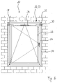
- the holding device demountable, for example, for purposes of cleaning the Remove window temporarily and the rotary wing - or even a tilting wing - temporarily To swing 90 ° or 180 °.
Landscapes
- Engineering & Computer Science (AREA)
- Structural Engineering (AREA)
- Civil Engineering (AREA)
- Mechanical Engineering (AREA)
- Architecture (AREA)
- Wing Frames And Configurations (AREA)
- Glass Compositions (AREA)
- Special Wing (AREA)
- Specific Sealing Or Ventilating Devices For Doors And Windows (AREA)
- Devices For Conveying Motion By Means Of Endless Flexible Members (AREA)
- Surgical Instruments (AREA)
- Control Of Combustion (AREA)
Abstract
Description
- Fig. 1
- eine Außenansicht und
- Fig. 2
- eine Innenansicht eines ersten erfindungsgemäßen Fensters,
- Fig. 3
- einen vertikalen Schnitt und
- Fig. 4
- einen horizontalen Schnitt durch dieses erste Fenster jeweils im gekippten Zustand,
- Fig. 5
- eine Außenansicht und
- Fig. 6
- eine Innenansicht eines zweiten erfindungsgemäßen Fensters,
- Fig. 7
- einen vertikalen Schnitt im gekippten Zustand,
- Fig. 8
- einen horizontalen Schnitt im geschlossenen Zustand und
- Fig. 9
- einen horizontalen Schnitt in Wartungsstellung durch dieses zweite Fenster,
- Fig. 10
- eine Außenansicht und
- Fig. 11
- eine Innenansicht eines dritten erfindungsgemäßen Fensters
- Fig. 12
- einen vertikalen Schnitt im geschlossenen und
- Fig. 13
- einen vertikalen Schnitt im gekippten Zustand sowie
- Fig. 14
- ein Detail eines vierten Fensters im geschlossenen und
- Fig. 15
- im gekippten Zustand jeweils im vertikalen Schnitt.
- Fig. 1'
- eine Außenansicht des Fensters;
- Fig. 2a'
- einen Vertikalschnitt entlang der Linie II-II durch das Fenster gemäß Figur 1' in der Schließstellung;
- Fig. 2b'
- wie Fig. 2a', jedoch in der Kippgrenzstellung;
- Fig. 3'
- einen Horizontalschnitt entlang der Linie III-III durch das Fenster gemäß Figur 1' und
- Fig. 4'
- eine Innenansicht des Fensters nach Fig. 1'.
Claims (23)
- Sprengwirkungshemmendes Fenster (1, 20, 38, 1') mit einem Blendrahmen (2, 24, 50, 56, 2') und einem Flügelrahmen (4, 22, 42, 60, 3'), der eine Füllung (6, 5') aufnimmt und in Scharnieren (3) an dem Blendrahmen (2, 24, 50, 56, 2') um mindestens eine Achse kippbar gelagert ist, wobei der Flügelrahmen (4, 22, 42, 60, 3') in einer Schließstellung (8) in dem Blendrahmen (2, 24, 50, 56, 2') einliegt, dadurch gekennzeichnet, dass die Füllung (6, 5') aus Panzerglas besteht und dass das Fenster (1, 20, 38, 1') mindestens ein Kippbegrenzungselement (10, 33, 39, 7'), mittels dessen ein durch eine Sprengwirkung induziertes Kippen des Flügelrahmens (4, 22, 42, 60, 3') in den Scharnieren (3) über eine Kippgrenzstellung (11, 28, 49) hinaus hemmbar ist und mindestens ein Verschiebebegrenzungselement (7, 23, 32, 48, 55, 7'), mittels dessen ein durch die Sprengwirkung induziertes Verschieben des Flügelrahmens (4, 22, 42, 60, 3') senkrecht zu einer Kippachse in den Scharnieren (3) hemmbar ist, aufweist.
- Fenster (1) nach dem vorgenannten Anspruch, dadurch gekennzeichnet, dass die Scharniere (3) verstärkt und dadurch als Verschiebebegrenzungselemente (7) ausgebildet sind.
- Fenster (20, 1') nach einem der vorgenannten Ansprüche, gekennzeichnet durch mindestens ein mit dem Blendrahmen (24, 2' ) und/oder der Fensterlaibung verbundenen Verschiebebegrenzungselement (32, 7'), das an einer den Scharnieren gegenüber liegenden Seite (29) des Flügelrahmens (22, 3') angeordnet ist und mittels dessen aus der Kippgrenzstellung (28) und aus jeder Stellung zwischen dieser und der Schließstellung ein durch die Sprengwirkung induziertes Verschieben des Flügelrahmens (22, 3') in einer Ebene der Füllung senkrecht zu der Kippachse dadurch hemmbar ist, dass der Flügelrahmen (22, 3') an einem kreissegmentförmig ausgebildeten Anschlag (30) an dem Verschiebebegrenzungselement (32, 7') anschlägt.
- Fenster (20, 38) nach einem der vorgenannten Ansprüche, gekennzeichnet durch mindestens ein zweiteiliges Verschiebebegrenzungselement (23, 48, 55), das in der Kippachse angeordnet ist, und das eine mit dem Blendrahmen (24, 50, 56) verbundene Matrize (25, 52, 57) und eine mit dem Flügelrahmen (22, 60) verbundene Patrize (26, 53, 62) aufweist, wobei die Matrize (25, 52, 57) und die Patrize (26, 53, 62) hakenförmige Verriegelungselemente (27) aufweisen, wobei in der Kippgrenzstellung (28, 49) und in jeder Stellung zwischen dieser und der Schließstellung das Verschieben dadurch hemmbar ist, dass die an Matrize (25, 52, 57) und Patrize (26, 53, 62) ausgebildeten Verriegelungselemente (27) in einander eingreifen.
- Fenster (20, 38) nach dem vorgenannten Anspruch, dadurch gekennzeichnet, dass die Patrize (26, 53, 62) mit einer an dem Flügelrahmen (22, 60) angebrachten Schubstange (61) verbunden und mit dieser entlang der Kippachse soweit verschiebbar ist, dass die Verriegelungselemente (27) zumindest in einer Drehstellung des Beschlags nicht mehr in einander eingreifen.
- Fenster (38) nach einem der vorgenannten Ansprüche, gekennzeichnet durch verstärkte und dadurch als Kippbegrenzungselement (39) ausgebildete Sicherheitsscheren (40), die einerseits in dem Blendrahmen (50, 56) und andererseits in dem Flügelrahmen (42, 60) gelagert sind.
- Fenster (1, 20, 1') nach einem der vorgenannten Ansprüche, gekennzeichnet durch mindestens ein mit dem Blendrahmen (24, 2') und/oder der Fensterlaibung verbundenen Kippbegrenzungselement (10, 33, 7'), das an der den Scharnieren (3) gegenüber liegenden Seite (9, 29) des Flügelrahmens (4, 22, 3') angeordnet ist, und an dem der Flügelrahmen (4, 22, 3') in der Kippgrenzstellung (11, 28) anschlägt.
- Fenster (20) nach dem vorgenannten Anspruch, dadurch gekennzeichnet, dass an beiden Enden der den Scharnieren gegenüber liegenden Seite (29) des Flügelrahmens (22) jeweils ein Kippbegrenzungselement (33) angeordnet ist.
- Fenster (1) nach einem der Ansprüche 7 oder 8, dadurch gekennzeichnet, dass das Kippbegrenzungselement (10) derart mit dem Blendrahmen (24) und/oder der Fensterlaibung verbundenen Fensterlaibung (13) verbindbar ist, in der das Fenster (1) einsetzbar ist, dass das Kippbegrenzungselement (10) zwischen einer Betriebsstellung (18) und einer Wartungsstellung (19) verschiebbar ist, wobei der Flügelrahmen (4, 22) in der Wartungsstellung (19) des Kippbegrenzungselements (10) über die Kippgrenzstellung (11, 28) hinaus öffenbar ist.
- Fenster (1) nach dem vorgenannten Anspruch, dadurch gekennzeichnet, dass das Kippbegrenzungselement (10) lösbar mit der Fensterlaibung (13) verschraubbar ist.
- Fenster (1) nach Anspruch 9 oder 10, dadurch gekennzeichnet, dass das Kippbegrenzungselement (10) in einer Ebene des Blendrahmens (2, 24) in Langlöchern (16) derart verschiebbar ist, dass es in seiner Wartungsstellung (19) einen größeren Abstand von den Scharnieren (3) aufweist als in seiner Betriebsstellung (18).
- Fenster (38) nach einem der Ansprüche 1 bis 5, dadurch gekennzeichnet, dass an der der Kippachse zugewandten Seite (46) des Flügelrahmens (42, 60) eine Nase (47) ausgebildet ist, die eine mit dem Blendrahmen (50, 56) verbundene Matrize (52, 57) und/oder einen nach innen weisenden Vorsprung des Blendrahmens (50, 56) selbst so hintergreift, dass eine Bewegung des Flügelrahmens (42, 60) in eine Richtung im wesentlichen parallel zu der Ebene der Füllung (6) und senkrecht zu der Kippachse gehemmt wird.
- Fenster (38) nach dem vorgenannten Anspruch, dadurch gekennzeichnet, dass eine mit dem Blendrahmen (50, 56) verbundene Matrize (52, 57) an ihrem dem Rauminneren zugewandten Ende mit einem nasenförmigen Verriegelungselement (59) versehen ist, das zunächst senkrecht zu der Ebene der Füllung (6) und dann parallel dazu verläuft und ein Verriegelungselement (V) der Patrize (53, 62) des Flügelrahmens (42, 60) überragt.
- Fenster (1') nach einem der vorgenannten Ansprüche, gekennzeichnet durch eine Halteeinrichtung (7'), mittels derer das Fenster (1') sowohl im Sinne des Kippbegrenzungselements gegen eine Fortsetzung der Drehbewegung über die Kippgrenzstellung hinaus als auch im Sinne des Verschiebebegrenzungselements gegen eine vom Fenster (1') weg gerichtete Bewegung innerhalb der Ebene der Füllung (5') abgestützt ist, und dass im Bereich eines das Drehgelenk des Flügelrahmens (3') verbindenden Rahmenschenkels (18') formschlüssige Schließelemente zwischen dem Flügelrahmen (3') und dem Blendrahmen (2') vorhanden sind, wobei der Öffnungswinkel (d) des Flügelrahmens (3') in der Kippgrenzstellung zwischen 5° und 50° beträgt.
- Fenster (1') nach dem vorgenannten Anspruch, dadurch gekennzeichnet, dass die Halteeinrichtung (7') eine durchgängige Stützfläche (28') aufweist, die sich von dem Blendrahmen (2') bis zu einer Anschlagfläche (12') erstreckt, an der der Flügelrahmen (3') in der Kippgrenzstellung anliegt, wobei die Stützfläche (28') parallel zu der Bahnkurve verläuft, die die Vorderkante (29') des Flügelrahmens (3') bei der Verlagerung von der Schließstellung in die Kippgrenzstellung beschreibt.
- Fenster (1') nach einem der Ansprüche 14 bis 15, dadurch gekennzeichnet, dass die Halteeinrichtung (7') aus einem die Stützfläche (28') aufweisenden Unterbügel (8') und einem senkrecht zur Ebene der Füllung (5') verlaufenden Oberbügel (9') besteht, wobei Unterbügel (8') und Oberbügel (9') sowohl im Bereich des Blendrahmens (2') als auch im Bereich der Anschlagfläche (12') miteinander verbunden sind.
- Fenster (1') nach einem der Ansprüche 14 bis 16, dadurch gekennzeichnet, dass ein Verankerungsabschnitt der Halteeinrichtung (7') von einem den Blendrahmen (2') mit einem Bauwerksteil verbindenden Anker (14') durchdrungen wird.
- Fenster nach dem vorgenannten Anspruch, dadurch gekennzeichnet, dass der Anker zur Befestigung des Blendrahmens mit einem im Querschnitt L-förmigen Winkel verbunden ist, der sich mit einem Schenkel parallel zu einer Fensterlaibung und mit dem anderen Schenkel parallel zu einer Ansichtsfläche des Gebäudes erstreckt.
- Fenster (1') nach einem der Ansprüche 14 bis 18, dadurch gekennzeichnet, dass zumindest ein Teil des von dem Flügelrahmen (3') in seiner Kippgrenzstellung freigegebenen Öffnungsquerschnitts von einem Lochblech (24') verdeckt ist, das mit einer Halteeinrichtung (7') verbunden ist.
- Fenster (1') nach dem vorgenannten Anspruch, dadurch gekennzeichnet, dass das Lochblech (24') zwei abgekantete schmalseitige Randstreifen (25') und einen längsseitigen Randstreifen (26') aufweist, der eine den Oberbügel (9') mit dem Unterbügel (8') verbindende Verbindungsstrebe (10') abdeckt.
- Fenster (1') nach einem der Ansprüche 15 bis 20, dadurch gekennzeichnet, dass die Anschlagfläche (12') von einem Elastomermaterial (11') gebildet wird.
- Fenster (1') nach einem der Ansprüche 14 bis 21, dadurch gekennzeichnet, dass die Schließelemente von zwei Winkelprofilen (17', 19') gebildet sind, die jeweils mit einem Befestigungsschenkel (22', 23') mit dem Flügelrahmen (3') und mit dem Blendrahmen (2') verbunden sind, sich vorzugsweise über die gesamte Länge der zugeordneten Rahmenschenkel (16', 18') erstrecken und sich jeweils mit einem Stützschenkel (20', 21') aneinander abstützen.
- Fenster (1') nach dem vorgenannten Anspruch, dadurch gekennzeichnet, dass die Stützschenkel (20', 21') in der Kippgrenzstellung aneinander anliegen und parallel zueinander ausgerichtet sind.
Priority Applications (2)
| Application Number | Priority Date | Filing Date | Title |
|---|---|---|---|
| PL04022051T PL1516996T3 (pl) | 2003-09-22 | 2004-09-16 | Okno chroniące przed wybuchem |
| EP05026185A EP1640550B1 (de) | 2003-09-22 | 2004-09-16 | Sprengwirkungshemmendes Fenster |
Applications Claiming Priority (4)
| Application Number | Priority Date | Filing Date | Title |
|---|---|---|---|
| DE10344168 | 2003-09-22 | ||
| DE10344168 | 2003-09-22 | ||
| DE102004011767 | 2004-03-09 | ||
| DE102004011767 | 2004-03-09 |
Related Child Applications (1)
| Application Number | Title | Priority Date | Filing Date |
|---|---|---|---|
| EP05026185A Division EP1640550B1 (de) | 2003-09-22 | 2004-09-16 | Sprengwirkungshemmendes Fenster |
Publications (3)
| Publication Number | Publication Date |
|---|---|
| EP1516996A2 true EP1516996A2 (de) | 2005-03-23 |
| EP1516996A3 EP1516996A3 (de) | 2005-06-08 |
| EP1516996B1 EP1516996B1 (de) | 2006-10-04 |
Family
ID=34195767
Family Applications (2)
| Application Number | Title | Priority Date | Filing Date |
|---|---|---|---|
| EP05026185A Expired - Lifetime EP1640550B1 (de) | 2003-09-22 | 2004-09-16 | Sprengwirkungshemmendes Fenster |
| EP04022051A Expired - Lifetime EP1516996B1 (de) | 2003-09-22 | 2004-09-16 | Sprengwirkungshemmendes Fenster |
Family Applications Before (1)
| Application Number | Title | Priority Date | Filing Date |
|---|---|---|---|
| EP05026185A Expired - Lifetime EP1640550B1 (de) | 2003-09-22 | 2004-09-16 | Sprengwirkungshemmendes Fenster |
Country Status (5)
| Country | Link |
|---|---|
| US (1) | US7546711B2 (de) |
| EP (2) | EP1640550B1 (de) |
| AT (1) | ATE341691T1 (de) |
| DE (2) | DE502004001651D1 (de) |
| PL (1) | PL1516996T3 (de) |
Cited By (6)
| Publication number | Priority date | Publication date | Assignee | Title |
|---|---|---|---|---|
| EP1818489A1 (de) | 2006-02-09 | 2007-08-15 | Sälzer Sicherheitstechnik GmbH | Sicherheitsfenster oder -tür in einbruchhemmender Ausführung |
| EP1892361A1 (de) * | 2006-08-15 | 2008-02-27 | Sälzer Sicherheitstechnik GmbH | Sicherheitsfenster oder -tür in einbruchhemmender Ausführung |
| EP1903172A1 (de) * | 2006-08-15 | 2008-03-26 | Sälzer Sicherheitstechnik GmbH | Sicherheitsfenster oder -tür in einbruchhemmender Ausführung |
| EP2149661A1 (de) * | 2008-07-25 | 2010-02-03 | Sälzer Sicherheitstechnik GmbH | Gebäudeabschluss in sprengwirkungshemmender und/oder einbruchhemmender Ausführung |
| DE202009005248U1 (de) | 2008-12-15 | 2010-02-11 | Sälzer Sicherheitstechnik GmbH | Gebäude mit mindestens einer Gebäudeöffnung und einem Gebäudeabschluss |
| EP2423426A1 (de) | 2010-08-31 | 2012-02-29 | Sälzer Sicherheitstechnik GmbH | Einbruchhemmender und/oder sprengwirkungshemmender Gebäudeabschluss |
Families Citing this family (16)
| Publication number | Priority date | Publication date | Assignee | Title |
|---|---|---|---|---|
| DE102004057470A1 (de) * | 2004-11-29 | 2006-06-01 | Sälzer Sicherheitstechnik GmbH | Explosionshemmendes Fenstersystem |
| US7975432B2 (en) * | 2006-09-05 | 2011-07-12 | Deceuninck North America, Llc | Casement window assembly with windload and impact resistance |
| ITBO20060897A1 (it) * | 2006-12-29 | 2008-06-30 | Gsg Int Spa | Infisso con apertura a vasistas. |
| EP2687669B1 (de) | 2007-08-03 | 2015-04-22 | VKR Holding A/S | Verfahren zum Befestigen einer Isoliergasscheibe an einem Fensterrahmen mittels eines Einsatzes im extrudierten Randstreifen |
| ES2593323T3 (es) | 2007-08-03 | 2016-12-07 | Vkr Holding A/S | Un método para fabricar un módulo de cristal y una ventana que comprende tal módulo de cristal |
| CN103032012B (zh) | 2007-08-03 | 2016-05-25 | Vkr控股公司 | 在窗户中使用的窗格组件 |
| DE202008010056U1 (de) | 2008-07-25 | 2008-10-02 | Sälzer Sicherheitstechnik GmbH | Sicherheitsfenster oder -tür |
| EP3299566B1 (de) * | 2009-02-03 | 2020-03-25 | VKR Holding A/S | Fenster mit einem flügelrahmen und mitteln zur verminderung von kondensation |
| DE102009027279A1 (de) * | 2009-06-29 | 2010-12-30 | Sälzer Sicherheitstechnik GmbH | Sprengwirkungshemmender und/oder einbbruchhemmender Gebäudeabschluss |
| MY180400A (en) * | 2013-12-03 | 2020-11-28 | Aja Entpr Pte Ltd | A panel assembly |
| EE01499U1 (et) * | 2017-12-28 | 2020-05-15 | As Amhold | Avatäitekonstruktsioon |
| RU182927U1 (ru) * | 2018-07-04 | 2018-09-06 | Антон Валерьевич Буленко | Легкосбрасываемая оконная конструкция |
| RU195434U1 (ru) * | 2019-11-20 | 2020-01-28 | Максим Александрович Ефремов | Узел крепления легкосбрасываемой конструкции |
| RU199687U1 (ru) * | 2020-03-26 | 2020-09-14 | Олег Александрович Петров | Разрушаемый элемент легкосбрасываемой оконной конструкции |
| RU207760U1 (ru) * | 2021-03-22 | 2021-11-15 | Максим Александрович Ефремов | Узел крепления легкосбрасываемой конструкции |
| RU208703U1 (ru) * | 2021-11-09 | 2021-12-30 | Виталий Геннадьевич Ружинский | Узел крепления легкосбрасываемой ограждающей строительной конструкции |
Citations (2)
| Publication number | Priority date | Publication date | Assignee | Title |
|---|---|---|---|---|
| DE3420883C2 (de) | 1983-07-28 | 1985-07-18 | Heinrich 3550 Marburg Sälzer | Sprengwirkungshemmende Verglasung |
| DE3432021C2 (de) | 1984-08-31 | 1987-11-19 | Heinrich 3550 Marburg De Saelzer |
Family Cites Families (18)
| Publication number | Priority date | Publication date | Assignee | Title |
|---|---|---|---|---|
| FR1399071A (fr) * | 1964-06-17 | 1965-05-14 | Corning Glass Works | Structure de fenêtre propre à résister à des efforts importants tels qu'exercés par de grands vents |
| GB2101192A (en) * | 1981-07-01 | 1983-01-12 | Paul Garside | Securing devices for closures |
| DE3643192A1 (de) * | 1986-12-18 | 1988-07-07 | Jakob Escher Gmbh | Vorrichtung zur verriegelung eines fluegelrahmens |
| DE3722965C1 (en) | 1987-07-11 | 1989-02-02 | Geze Grundstueck Beteiligung | Safety fitting |
| DE3817966C2 (de) * | 1988-05-27 | 1995-02-23 | Schueco Int Gmbh & Co | Vorrichtung zur Verriegelung eines Flügelrahmens eines Fensters oder einer Tür |
| GB2282850B (en) * | 1993-10-13 | 1996-11-13 | Peter Eric Cotterill | Security device |
| DE59508356D1 (de) * | 1995-01-05 | 2000-06-21 | Werner Lautenschlaeger | Vorrichtung zur wärmebehandlung von materialien in einer heizkammer |
| DE29514070U1 (de) * | 1995-09-02 | 1995-10-19 | Ettischer, Helmut, 73760 Ostfildern | Riegelsicherung |
| US6010758A (en) * | 1997-06-12 | 2000-01-04 | Anglin, Jr.; Richard L. | Shrapnel mitigation system |
| US6185882B1 (en) * | 1997-07-28 | 2001-02-13 | Gregory M. Pearson | Bullet resistant window assembly |
| DE29804797U1 (de) | 1998-03-17 | 1998-05-14 | Wagner Gb Ltd | Fenster oder Tür |
| IL123980A (en) * | 1998-04-07 | 2000-10-31 | Arpal Aluminum Ltd | Blast resistant window framework and elements thereof |
| DE29810095U1 (de) * | 1998-06-05 | 1998-09-03 | Sälzer Sicherheitstechnik GmbH, 35037 Marburg | Tür oder Fenster |
| US6167656B1 (en) * | 1999-03-09 | 2001-01-02 | Fortress Security Windows Inc. | Security window assembly |
| DE19916338C2 (de) | 1999-04-12 | 2002-10-31 | Unilux Ag | Sicherheitsvorrichtung für ein Fenster und Fenster mit einer solchen Sicherheitsvorrichtung |
| DE20102942U1 (de) | 2001-02-19 | 2001-10-11 | Diecks, Karl-Freddy, 59519 Möhnesee | Insektenschutzeinrichtung für Dach-/Kippflügelfenster u. Dreh-/Kippflügeltüren mit integrierter Einbruchshemmung |
| DE10164212B4 (de) | 2001-12-31 | 2009-06-18 | Bernhard Haverkamp | Sprengwirkungshemmendes Fenster |
| US6843023B2 (en) * | 2002-12-19 | 2005-01-18 | Jin Huo Liu | Dual casement window structure |
-
2004
- 2004-09-16 PL PL04022051T patent/PL1516996T3/pl unknown
- 2004-09-16 EP EP05026185A patent/EP1640550B1/de not_active Expired - Lifetime
- 2004-09-16 DE DE502004001651T patent/DE502004001651D1/de not_active Expired - Lifetime
- 2004-09-16 EP EP04022051A patent/EP1516996B1/de not_active Expired - Lifetime
- 2004-09-16 AT AT04022051T patent/ATE341691T1/de active
- 2004-09-16 DE DE502004005569T patent/DE502004005569D1/de not_active Expired - Lifetime
- 2004-09-22 US US10/947,402 patent/US7546711B2/en not_active Expired - Fee Related
Patent Citations (2)
| Publication number | Priority date | Publication date | Assignee | Title |
|---|---|---|---|---|
| DE3420883C2 (de) | 1983-07-28 | 1985-07-18 | Heinrich 3550 Marburg Sälzer | Sprengwirkungshemmende Verglasung |
| DE3432021C2 (de) | 1984-08-31 | 1987-11-19 | Heinrich 3550 Marburg De Saelzer |
Cited By (6)
| Publication number | Priority date | Publication date | Assignee | Title |
|---|---|---|---|---|
| EP1818489A1 (de) | 2006-02-09 | 2007-08-15 | Sälzer Sicherheitstechnik GmbH | Sicherheitsfenster oder -tür in einbruchhemmender Ausführung |
| EP1892361A1 (de) * | 2006-08-15 | 2008-02-27 | Sälzer Sicherheitstechnik GmbH | Sicherheitsfenster oder -tür in einbruchhemmender Ausführung |
| EP1903172A1 (de) * | 2006-08-15 | 2008-03-26 | Sälzer Sicherheitstechnik GmbH | Sicherheitsfenster oder -tür in einbruchhemmender Ausführung |
| EP2149661A1 (de) * | 2008-07-25 | 2010-02-03 | Sälzer Sicherheitstechnik GmbH | Gebäudeabschluss in sprengwirkungshemmender und/oder einbruchhemmender Ausführung |
| DE202009005248U1 (de) | 2008-12-15 | 2010-02-11 | Sälzer Sicherheitstechnik GmbH | Gebäude mit mindestens einer Gebäudeöffnung und einem Gebäudeabschluss |
| EP2423426A1 (de) | 2010-08-31 | 2012-02-29 | Sälzer Sicherheitstechnik GmbH | Einbruchhemmender und/oder sprengwirkungshemmender Gebäudeabschluss |
Also Published As
| Publication number | Publication date |
|---|---|
| EP1516996B1 (de) | 2006-10-04 |
| ATE341691T1 (de) | 2006-10-15 |
| DE502004001651D1 (de) | 2006-11-16 |
| US7546711B2 (en) | 2009-06-16 |
| EP1640550B1 (de) | 2007-11-21 |
| EP1516996A3 (de) | 2005-06-08 |
| EP1640550A2 (de) | 2006-03-29 |
| EP1640550A3 (de) | 2006-08-02 |
| US20050102933A1 (en) | 2005-05-19 |
| DE502004005569D1 (de) | 2008-01-03 |
| PL1516996T3 (pl) | 2007-02-28 |
Similar Documents
| Publication | Publication Date | Title |
|---|---|---|
| EP1640550B1 (de) | Sprengwirkungshemmendes Fenster | |
| EP0653012B1 (de) | Jalousierbarer rolladen | |
| EP1944432B1 (de) | Explosionshemmendes Bauelement | |
| EP1312743B1 (de) | Sperr- und Sicherungsvorrichtung für einen Hebe- und Schiebeflügel; Treibstangenbeschlag mit einer solchen Vorrichtung; Hebe- und Schiebetür bzw. -fenster mit einer solchen Vorrichtung | |
| EP2617934B1 (de) | Brandschutztüre | |
| DE69101943T2 (de) | Tür für Schaltschrank. | |
| EP2149661B1 (de) | Gebäudeabschluss in sprengwirkungshemmender und/oder einbruchhemmender Ausführung | |
| EP2058459B1 (de) | Gebäudeabschluss mit Panik-Entriegelungselement in einbruchhemmender Ausführung | |
| EP1892361B1 (de) | Sicherheitsfenster oder -tür in einbruchhemmender Ausführung | |
| EP1936086B1 (de) | Ecklagerbeschlag für Fenster, Türen oder dgl. | |
| EP3695081B1 (de) | Tor mit einem unteren torglied mit klapprollenhalter | |
| DE10208975B4 (de) | Kunststofffenster oder -tür | |
| DE202004006268U1 (de) | Sprengwirkungshemmendes Fenster | |
| DE10164212B4 (de) | Sprengwirkungshemmendes Fenster | |
| EP3859095B1 (de) | Lamellendach mit druckfeder | |
| EP0777026A1 (de) | Dreh-Kipp-Beschlag für Fenster, Türen oder dergleichen | |
| EP1818489B1 (de) | Sicherheitsfenster oder -tür in einbruchhemmender Ausführung | |
| DE69901359T2 (de) | Zwischengeschaltete Sicherheitsvorrichtung für Drehtür oder Drehfenster | |
| DE19545375C2 (de) | Tür insbesondere Falttür | |
| DE19605047A1 (de) | Dreh-Kipp-Beschlag für Fenster, Türen oder dergleichen | |
| AT505570B1 (de) | Zarge mit falz für zumindest einen flügel | |
| DE20310069U1 (de) | Sprengwirkungshemmende Verglasung | |
| DE102004015353B3 (de) | Sprengwirkungshemmend ausgebildetes Fenster | |
| DE10238627A1 (de) | Beschlagelement | |
| DE202004014473U1 (de) | Sprengwirkungshemmend ausgebildetes Fenster |
Legal Events
| Date | Code | Title | Description |
|---|---|---|---|
| PUAI | Public reference made under article 153(3) epc to a published international application that has entered the european phase |
Free format text: ORIGINAL CODE: 0009012 |
|
| AK | Designated contracting states |
Kind code of ref document: A2 Designated state(s): AT BE BG CH CY CZ DE DK EE ES FI FR GB GR HU IE IT LI LU MC NL PL PT RO SE SI SK TR |
|
| AX | Request for extension of the european patent |
Extension state: AL HR LT LV MK |
|
| PUAL | Search report despatched |
Free format text: ORIGINAL CODE: 0009013 |
|
| AK | Designated contracting states |
Kind code of ref document: A3 Designated state(s): AT BE BG CH CY CZ DE DK EE ES FI FR GB GR HU IE IT LI LU MC NL PL PT RO SE SI SK TR |
|
| AX | Request for extension of the european patent |
Extension state: AL HR LT LV MK |
|
| 17P | Request for examination filed |
Effective date: 20050706 |
|
| GRAP | Despatch of communication of intention to grant a patent |
Free format text: ORIGINAL CODE: EPIDOSNIGR1 |
|
| GRAS | Grant fee paid |
Free format text: ORIGINAL CODE: EPIDOSNIGR3 |
|
| AKX | Designation fees paid |
Designated state(s): AT BE DE FR GB PL |
|
| GRAA | (expected) grant |
Free format text: ORIGINAL CODE: 0009210 |
|
| AK | Designated contracting states |
Kind code of ref document: B1 Designated state(s): AT BE DE FR GB PL |
|
| REG | Reference to a national code |
Ref country code: GB Ref legal event code: FG4D Free format text: NOT ENGLISH |
|
| REF | Corresponds to: |
Ref document number: 502004001651 Country of ref document: DE Date of ref document: 20061116 Kind code of ref document: P |
|
| GBT | Gb: translation of ep patent filed (gb section 77(6)(a)/1977) |
Effective date: 20061101 |
|
| REG | Reference to a national code |
Ref country code: PL Ref legal event code: T3 |
|
| ET | Fr: translation filed | ||
| PLBE | No opposition filed within time limit |
Free format text: ORIGINAL CODE: 0009261 |
|
| STAA | Information on the status of an ep patent application or granted ep patent |
Free format text: STATUS: NO OPPOSITION FILED WITHIN TIME LIMIT |
|
| 26N | No opposition filed |
Effective date: 20070705 |
|
| PGFP | Annual fee paid to national office [announced via postgrant information from national office to epo] |
Ref country code: PL Payment date: 20110909 Year of fee payment: 8 Ref country code: AT Payment date: 20110929 Year of fee payment: 8 |
|
| REG | Reference to a national code |
Ref country code: AT Ref legal event code: MM01 Ref document number: 341691 Country of ref document: AT Kind code of ref document: T Effective date: 20120916 |
|
| PG25 | Lapsed in a contracting state [announced via postgrant information from national office to epo] |
Ref country code: AT Free format text: LAPSE BECAUSE OF NON-PAYMENT OF DUE FEES Effective date: 20120916 |
|
| PG25 | Lapsed in a contracting state [announced via postgrant information from national office to epo] |
Ref country code: PL Free format text: LAPSE BECAUSE OF NON-PAYMENT OF DUE FEES Effective date: 20120916 |
|
| REG | Reference to a national code |
Ref country code: PL Ref legal event code: LAPE |
|
| REG | Reference to a national code |
Ref country code: DE Ref legal event code: R082 Ref document number: 502004001651 Country of ref document: DE Representative=s name: BAUER WAGNER PRIESMEYER, PATENT- UND RECHTSANW, DE Effective date: 20131205 Ref country code: DE Ref legal event code: R081 Ref document number: 502004001651 Country of ref document: DE Owner name: SAELZER GMBH, DE Free format text: FORMER OWNER: SAELZER SICHERHEITSTECHNIK GMBH, 35037 MARBURG, DE Effective date: 20131205 Ref country code: DE Ref legal event code: R082 Ref document number: 502004001651 Country of ref document: DE Representative=s name: PATENT- & RECHTSANWAELTE BAUER WAGNER PRIESMEY, DE Effective date: 20131205 |
|
| PGFP | Annual fee paid to national office [announced via postgrant information from national office to epo] |
Ref country code: FR Payment date: 20140929 Year of fee payment: 11 |
|
| REG | Reference to a national code |
Ref country code: FR Ref legal event code: ST Effective date: 20160531 |
|
| PG25 | Lapsed in a contracting state [announced via postgrant information from national office to epo] |
Ref country code: FR Free format text: LAPSE BECAUSE OF NON-PAYMENT OF DUE FEES Effective date: 20150930 |
|
| REG | Reference to a national code |
Ref country code: DE Ref legal event code: R082 Ref document number: 502004001651 Country of ref document: DE Representative=s name: PATENT- UND RECHTSANWAELTE LOESENBECK, SPECHT,, DE Ref country code: DE Ref legal event code: R082 Ref document number: 502004001651 Country of ref document: DE Representative=s name: BAUER WAGNER PELLENGAHR SROKA PATENT- & RECHTS, DE |
|
| PGFP | Annual fee paid to national office [announced via postgrant information from national office to epo] |
Ref country code: BE Payment date: 20220926 Year of fee payment: 19 |
|
| REG | Reference to a national code |
Ref country code: DE Ref legal event code: R082 Ref document number: 502004001651 Country of ref document: DE Representative=s name: PATENT- UND RECHTSANWAELTE LOESENBECK, SPECHT,, DE |
|
| P01 | Opt-out of the competence of the unified patent court (upc) registered |
Effective date: 20230818 |
|
| PGFP | Annual fee paid to national office [announced via postgrant information from national office to epo] |
Ref country code: GB Payment date: 20230728 Year of fee payment: 20 |
|
| PGFP | Annual fee paid to national office [announced via postgrant information from national office to epo] |
Ref country code: DE Payment date: 20230728 Year of fee payment: 20 |
|
| REG | Reference to a national code |
Ref country code: BE Ref legal event code: MM Effective date: 20230930 |
|
| PG25 | Lapsed in a contracting state [announced via postgrant information from national office to epo] |
Ref country code: BE Free format text: LAPSE BECAUSE OF NON-PAYMENT OF DUE FEES Effective date: 20230930 |
|
| REG | Reference to a national code |
Ref country code: DE Ref legal event code: R071 Ref document number: 502004001651 Country of ref document: DE |
|
| REG | Reference to a national code |
Ref country code: GB Ref legal event code: PE20 Expiry date: 20240915 |
|
| PG25 | Lapsed in a contracting state [announced via postgrant information from national office to epo] |
Ref country code: GB Free format text: LAPSE BECAUSE OF EXPIRATION OF PROTECTION Effective date: 20240915 |
|
| PG25 | Lapsed in a contracting state [announced via postgrant information from national office to epo] |
Ref country code: GB Free format text: LAPSE BECAUSE OF EXPIRATION OF PROTECTION Effective date: 20240915 |