EP1517005A1 - Gasturbine mit einem Abdichtdelement mit Lamellenstruktur - Google Patents
Gasturbine mit einem Abdichtdelement mit Lamellenstruktur Download PDFInfo
- Publication number
- EP1517005A1 EP1517005A1 EP04292228A EP04292228A EP1517005A1 EP 1517005 A1 EP1517005 A1 EP 1517005A1 EP 04292228 A EP04292228 A EP 04292228A EP 04292228 A EP04292228 A EP 04292228A EP 1517005 A1 EP1517005 A1 EP 1517005A1
- Authority
- EP
- European Patent Office
- Prior art keywords
- upstream
- seal
- annular structure
- spoiler
- flange
- Prior art date
- Legal status (The legal status is an assumption and is not a legal conclusion. Google has not performed a legal analysis and makes no representation as to the accuracy of the status listed.)
- Granted
Links
- 238000007789 sealing Methods 0.000 title claims abstract description 11
- 238000011144 upstream manufacturing Methods 0.000 claims abstract description 55
- 238000005070 sampling Methods 0.000 claims abstract description 5
- 210000003462 vein Anatomy 0.000 claims description 12
- 238000002485 combustion reaction Methods 0.000 claims description 11
- 230000000717 retained effect Effects 0.000 claims description 6
- 230000000740 bleeding effect Effects 0.000 claims 1
- 238000006073 displacement reaction Methods 0.000 description 6
- 238000009434 installation Methods 0.000 description 3
- 238000000034 method Methods 0.000 description 3
- 230000000694 effects Effects 0.000 description 2
- 238000005516 engineering process Methods 0.000 description 2
- 230000004907 flux Effects 0.000 description 2
- 238000002513 implantation Methods 0.000 description 2
- 208000031968 Cadaver Diseases 0.000 description 1
- 241000446313 Lamella Species 0.000 description 1
- 230000003416 augmentation Effects 0.000 description 1
- 238000001816 cooling Methods 0.000 description 1
- 238000003032 molecular docking Methods 0.000 description 1
- 230000000284 resting effect Effects 0.000 description 1
- 238000009423 ventilation Methods 0.000 description 1
Images

Classifications
-
- F—MECHANICAL ENGINEERING; LIGHTING; HEATING; WEAPONS; BLASTING
- F02—COMBUSTION ENGINES; HOT-GAS OR COMBUSTION-PRODUCT ENGINE PLANTS
- F02K—JET-PROPULSION PLANTS
- F02K1/00—Plants characterised by the form or arrangement of the jet pipe or nozzle; Jet pipes or nozzles peculiar thereto
- F02K1/78—Other construction of jet pipes
- F02K1/80—Couplings or connections
-
- F—MECHANICAL ENGINEERING; LIGHTING; HEATING; WEAPONS; BLASTING
- F02—COMBUSTION ENGINES; HOT-GAS OR COMBUSTION-PRODUCT ENGINE PLANTS
- F02C—GAS-TURBINE PLANTS; AIR INTAKES FOR JET-PROPULSION PLANTS; CONTROLLING FUEL SUPPLY IN AIR-BREATHING JET-PROPULSION PLANTS
- F02C7/00—Features, components parts, details or accessories, not provided for in, or of interest apart form groups F02C1/00 - F02C6/00; Air intakes for jet-propulsion plants
- F02C7/28—Arrangement of seals
-
- F—MECHANICAL ENGINEERING; LIGHTING; HEATING; WEAPONS; BLASTING
- F01—MACHINES OR ENGINES IN GENERAL; ENGINE PLANTS IN GENERAL; STEAM ENGINES
- F01D—NON-POSITIVE DISPLACEMENT MACHINES OR ENGINES, e.g. STEAM TURBINES
- F01D11/00—Preventing or minimising internal leakage of working-fluid, e.g. between stages
- F01D11/005—Sealing means between non relatively rotating elements
-
- F—MECHANICAL ENGINEERING; LIGHTING; HEATING; WEAPONS; BLASTING
- F01—MACHINES OR ENGINES IN GENERAL; ENGINE PLANTS IN GENERAL; STEAM ENGINES
- F01D—NON-POSITIVE DISPLACEMENT MACHINES OR ENGINES, e.g. STEAM TURBINES
- F01D25/00—Component parts, details, or accessories, not provided for in, or of interest apart from, other groups
- F01D25/24—Casings; Casing parts, e.g. diaphragms, casing fastenings
- F01D25/246—Fastening of diaphragms or stator-rings
-
- F—MECHANICAL ENGINEERING; LIGHTING; HEATING; WEAPONS; BLASTING
- F02—COMBUSTION ENGINES; HOT-GAS OR COMBUSTION-PRODUCT ENGINE PLANTS
- F02K—JET-PROPULSION PLANTS
- F02K1/00—Plants characterised by the form or arrangement of the jet pipe or nozzle; Jet pipes or nozzles peculiar thereto
-
- F—MECHANICAL ENGINEERING; LIGHTING; HEATING; WEAPONS; BLASTING
- F16—ENGINEERING ELEMENTS AND UNITS; GENERAL MEASURES FOR PRODUCING AND MAINTAINING EFFECTIVE FUNCTIONING OF MACHINES OR INSTALLATIONS; THERMAL INSULATION IN GENERAL
- F16J—PISTONS; CYLINDERS; SEALINGS
- F16J15/00—Sealings
- F16J15/02—Sealings between relatively-stationary surfaces
- F16J15/06—Sealings between relatively-stationary surfaces with solid packing compressed between sealing surfaces
- F16J15/08—Sealings between relatively-stationary surfaces with solid packing compressed between sealing surfaces with exclusively metal packing
- F16J15/0887—Sealings between relatively-stationary surfaces with solid packing compressed between sealing surfaces with exclusively metal packing the sealing effect being obtained by elastic deformation of the packing
-
- F—MECHANICAL ENGINEERING; LIGHTING; HEATING; WEAPONS; BLASTING
- F05—INDEXING SCHEMES RELATING TO ENGINES OR PUMPS IN VARIOUS SUBCLASSES OF CLASSES F01-F04
- F05D—INDEXING SCHEME FOR ASPECTS RELATING TO NON-POSITIVE-DISPLACEMENT MACHINES OR ENGINES, GAS-TURBINES OR JET-PROPULSION PLANTS
- F05D2240/00—Components
- F05D2240/10—Stators
- F05D2240/11—Shroud seal segments
-
- F—MECHANICAL ENGINEERING; LIGHTING; HEATING; WEAPONS; BLASTING
- F05—INDEXING SCHEMES RELATING TO ENGINES OR PUMPS IN VARIOUS SUBCLASSES OF CLASSES F01-F04
- F05D—INDEXING SCHEME FOR ASPECTS RELATING TO NON-POSITIVE-DISPLACEMENT MACHINES OR ENGINES, GAS-TURBINES OR JET-PROPULSION PLANTS
- F05D2240/00—Components
- F05D2240/10—Stators
- F05D2240/12—Fluid guiding means, e.g. vanes
Definitions
- the invention relates to a turbojet comprising upstream downstream, upstream and downstream being defined by the flow direction of flow primary, a high-pressure compressor, a diffuser grille and a combustion chamber, said high pressure compressor comprising an outer shell radially delimiting the vein of said primary flow and connected to an annular structure which extends radially towards the outside, said diffuser grille having in the axial extension of said compressor outer shroud an outer casing connected to a conical leg oriented towards the rear and delimiting upstream the bottom of said combustion chamber, said leg being itself connected to an outer housing shell which extends upstream and is attached to the annular structure by fixing means, said jamb, said ferrule outer casing and said annular structure defining a cavity around said diffuser grille, air sampling orifices being arranged in said leg to port the bottom of chamber with said cavity, said outer shell of casing being equipped outlets of the air taken, and sealing means being provided between said annular structure and said external grill cover diffuser for isolating said cavity from the vein of the primary stream.
- the air intake necessary for the cabin of the equipped aircraft of at least one turbojet engine is carried out in the bottom chamber of combustion in an area where it least disrupts the overall performance of the engine.
- the sampling takes place through the holes of the jamb, which allows easy installation of the outlets of the air taken. This provision imposes a relative sealing between the vein of the high-pressure compressor and the cavity located above the grid of the diffuser.
- the current technology chosen to ensure the tightness between the compressor and the outer casing of the grid is of the type joined to the lamella and counter-joint supported by springs. This technology makes it possible effect a sufficiently ample displacement between the two parts.
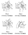
- Figure 1 shows the last stage of a high-pressure compressor 1 of a turbojet engine presenting, from upstream to downstream in the direction of the primary flow F1, a crown of fixed vanes 2 which extend radially inwards to from an outer casing 3, followed by a rotor blade 4 mounted on the periphery of a compressor wheel 5 and extending towards the outside to an outer ring 6 of delimiting compressor radially with the outer casing 3 the vein of the primary flow, this ferrule 6 being connected to an annular structure 7 having a section V in the plane containing the axis of the turbojet, and extending radially outward and attached to the outer casing of the engine by bolting.
- a diffuser grid 10 Downstream of the compressor 1 is provided a diffuser grid 10 which receives compressed air from the compressor 1 and delivers it to a combustion chamber 11.
- the grid 10 presents in the extension axial of the outer shell 6 of the compressor 1 an outer casing 12 connected to a conical leg 13 facing the rear of the turbojet, this leg 13 defines the upstream wall of the bottom of the chamber of 11 and is connected in its radially outer region to an outer shroud 14 of casing which extends upstream, and which presents an upstream flange 15 for fixing by bolting the assembly consisting of the combustion chamber and the diffuser on a flange 16 radially outside of the annular structure 7.
- a cavity 20 surrounding the diffuser grid 10 is thus defined axially by the annular structure 7 and the jamb 13, radially on the outside by the outer ring 14 of the casing and radially to the inside by the downstream portion 6a of the outer shell 6 of the compressor and by the upstream portion 12a of the outer casing 12, a gap 21 separating these two portions.
- the jamb 13 has orifices 22 of air intake in chamber bottom and casing external shell 14 is equipped with mouths 23 to provide an air flow for the ventilation of the cabin of the airplane or for cooling other elements of the turbojet engine.
- the portion radially internal structure of the annular structure 7 has a spoiler ring 40 which extends axially in the cavity 20 and whose end is above the upstream flange 33a in the absence of displacement between the outer shell 6 of the compressor 1 and the outer casing 12 of the diffuser, as shown in Figure 2.
- the springs 35 press on the joints in the annular zone separating the spoiler 40 from the upstream flange 33a.
- the pressure of the air is slightly higher in the cavity 20 with respect to the pressure in the vein at gap 21.
- the seals 30 side spoiler 40 and upstream flange side 33a have convex surfaces.
- the combined efforts of the springs 35 and the pressure deviation on both sides of the seals 30 apply the slats 30, which are flat on these surfaces in the configuration shown in Figure 2, which ensures the seal.
- the support between the slats 30 and the spoiler 40 leaves a game of escape, especially when the spoiler 40 passes above the groove 32, as shown in Figures 4 and 5.
- the strips 30 move away from the spoiler and only the difference in pressure between the two faces that is weak can prevent the creation of this spacing. It then occurs a flight game 41 between the lamellae and the end of the spoiler 40.
- the object of the invention is to ensure a perfect seal between the cavity and the vein of the primary flow whatever the variations of the gap and whatever the difference in air pressure between the two faces of the sealed area.
- the invention achieves its goal by the fact that the means sealing members have first and second seals of the sectorized type with louvres lined with counterjoints and urged by springs, said first seal being mounted in a first groove provided around the upstream part of the outer casing of the diffuser grille, the lamellae of this first seal bearing on the downstream end of a first spoiler integral with the annular structure, and said second seal being mounted in a second groove provided under said annular structure, the lamellae of this second seal being supported on the upstream end of a second spoiler secured to said annular structure and on the end upstream of a third spoiler secured to said upstream portion of the housing external.
- Installing a second inverted gasket allows to answer all the variations of direction of the difference of pressure but also strengthens the system by bringing a difficulty of passage extra for very small gradients because of the existence of a between the two joints.
- the first groove is delimited by an upstream flange and a downstream flange, the first seal and the first springs being retained means of rivets fixed on said flanges, and the third spoiler is formed on the upstream face of said upstream flange.
- the annular structure has a portion radially rearward facing, and the second groove is delimited by said portion and a third flange located above the upstream flange, the first spoiler extending downstream from the radially end interior of said third flange, said end further having a second spoiler which extends upstream and on which the second seal is in support.
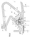
- FIGS. 1 to 5 shows the sealing system proposed by the invention for isolating the cavity 20 of the vein of the primary flow F1. Sure this figure, the various elements delimiting the cavity 20 bear the same references as the identical elements of FIGS. 1 to 5.
- the sealing system comprises a first seal 50 mounted on the periphery of the upstream portion 12a of the outer casing 12 of the diffuser grille 10. This first seal being similar to that of the state of the art illustrated in FIG. 2, and a second seal 60 located upstream of the first seal 50, also of the type to slats, and carried by the radially inner portion 7a of the structure ring 7 of the compressor.
- this part 7a which extends substantially parallel to the jamb 13, present above the upstream flange 33a, a third flange 70 which extends radially inwards and whose the radially inner end has a first spoiler 71 which extends downstream and a second spoiler 72 which extends upstream.
- the strips 30 of the first seal 50 bear on the end free of the first spoiler 71.
- These slats are retained in the groove 32 separating the upstream flange 33a from the downstream flange 33b by rivets 34, and are resting on the downstream face of the upstream flange 33a and on the free end of the first spoiler 71 thanks to the springs 35 also retained by the rivets 34 and pressing on the upstream face of the downstream flange 33b.
- the third flange 70 delimits with the part 7a of the structure annular groove 73 having the function of the groove 32. Pins carried by the third flange 70 hold the regions radially external lamellae 30 and counterjoints 31 of the second seal 60.
- Part 7a also comprises upstream of the third flange tabs 74 which serve to hold second springs 75 by riveting, these second springs exerting forces on the counterjoints 31 and lamellae 30 of the second seal 60 so that these lamellae support on the one hand on the upstream end of the second spoiler 72 and on a third spoiler 76 formed on the periphery of the upstream face of the flange upstream 33a.
- the extent of the first 71 and second 72 spoilers is such that these spoilers are always arranged over the upstream flange 33a, irrespective of the relative axial displacements of these two elements in operation.
- the distance separating the ends of the first spoiler 71 and the second spoiler 72 is less than the thickness of the upstream flange 33a increased by length of third spoiler 76.
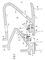
- Figure 7 shows the arrangement of the first seal 50 on the assembly constituted by the diffuser and the combustion chamber, and the arrangement of the second gasket on the compressor before mounting these two pieces.
Landscapes
- Engineering & Computer Science (AREA)
- General Engineering & Computer Science (AREA)
- Mechanical Engineering (AREA)
- Chemical & Material Sciences (AREA)
- Combustion & Propulsion (AREA)
- Structures Of Non-Positive Displacement Pumps (AREA)
- Turbine Rotor Nozzle Sealing (AREA)
- Gasket Seals (AREA)
Applications Claiming Priority (2)
| Application Number | Priority Date | Filing Date | Title |
|---|---|---|---|
| FR0311020 | 2003-09-19 | ||
| FR0311020A FR2860039B1 (fr) | 2003-09-19 | 2003-09-19 | Realisation de l'etancheite dans un turboreacteur pour le prelevement cabine par joints double sens a lamelles |
Publications (2)
| Publication Number | Publication Date |
|---|---|
| EP1517005A1 true EP1517005A1 (de) | 2005-03-23 |
| EP1517005B1 EP1517005B1 (de) | 2007-01-03 |
Family
ID=34178923
Family Applications (1)
| Application Number | Title | Priority Date | Filing Date |
|---|---|---|---|
| EP04292228A Expired - Lifetime EP1517005B1 (de) | 2003-09-19 | 2004-09-17 | Gasturbine mit einem Abdichtdelement mit Lamellenstruktur |
Country Status (9)
| Country | Link |
|---|---|
| US (1) | US7040098B2 (de) |
| EP (1) | EP1517005B1 (de) |
| JP (1) | JP4047843B2 (de) |
| KR (1) | KR101146402B1 (de) |
| CN (1) | CN100427736C (de) |
| DE (1) | DE602004004023T2 (de) |
| FR (1) | FR2860039B1 (de) |
| RU (1) | RU2345233C2 (de) |
| UA (1) | UA84267C2 (de) |
Cited By (3)
| Publication number | Priority date | Publication date | Assignee | Title |
|---|---|---|---|---|
| FR2913051A1 (fr) * | 2007-02-28 | 2008-08-29 | Snecma Sa | Etage de turbine dans une turbomachine |
| EP2559860A3 (de) * | 2011-08-19 | 2017-10-11 | General Electric Company | Dichtungsanordnung für Turbomaschinen |
| EP3736413A1 (de) * | 2019-05-10 | 2020-11-11 | Safran Aircraft Engines | Turbotriebwerksmodul, das mit einer haltevorrichtung für dichtungslamellen ausgestattet ist |
Families Citing this family (26)
| Publication number | Priority date | Publication date | Assignee | Title |
|---|---|---|---|---|
| FR2860041B1 (fr) * | 2003-09-22 | 2005-11-25 | Snecma Moteurs | Realisation de l'etancheite dans un turboreacteur pour le prelevement cabine par tube a double rotule |
| KR101065846B1 (ko) | 2005-11-17 | 2011-09-19 | 한국전자통신연구원 | Ofdma에서의 패킷 데이터 전송 방법 및 장치 |
| US7775048B2 (en) * | 2006-06-30 | 2010-08-17 | General Electric Company | Seal assembly |
| US7793507B2 (en) * | 2006-09-07 | 2010-09-14 | General Electric Company | Expansion joint for gas turbines |
| US7744092B2 (en) * | 2007-04-30 | 2010-06-29 | General Electric Company | Methods and apparatus to facilitate sealing in rotary machines |
| US7900461B2 (en) * | 2007-05-31 | 2011-03-08 | Rolls-Royce Corporation | Combustor liner support and seal assembly |
| US7909300B2 (en) * | 2007-10-18 | 2011-03-22 | General Electric Company | Combustor bracket assembly |
| US8534076B2 (en) * | 2009-06-09 | 2013-09-17 | Honeywell Internationl Inc. | Combustor-turbine seal interface for gas turbine engine |
| US8388307B2 (en) * | 2009-07-21 | 2013-03-05 | Honeywell International Inc. | Turbine nozzle assembly including radially-compliant spring member for gas turbine engine |
| CA2828313C (en) | 2011-02-28 | 2015-01-27 | Alstom Technology Ltd. | Turbine comprising a sealing device between the stator blade carrier and the housing |
| GB201105103D0 (en) * | 2011-03-28 | 2011-05-11 | Rolls Royce Plc | Securing system |
| US9200565B2 (en) * | 2011-12-05 | 2015-12-01 | Siemens Energy, Inc. | Full hoop casing for midframe of industrial gas turbine engine |
| FR2989426B1 (fr) * | 2012-04-11 | 2014-03-28 | Snecma | Turbomachine, telle qu'un turboreacteur ou un turbopropulseur d'avion |
| RU2525384C2 (ru) * | 2012-11-07 | 2014-08-10 | Российская Федерация, от имени которой выступает Министерство промышленности и торговли Российской Федерации (Минпромторг России) | Статор компрессора газотурбинного двигателя |
| WO2014152111A1 (en) * | 2013-03-14 | 2014-09-25 | United Technologies Corporation | Triple flange arrangement for a gas turbine engine |
| US9850771B2 (en) * | 2014-02-07 | 2017-12-26 | United Technologies Corporation | Gas turbine engine sealing arrangement |
| KR101560730B1 (ko) * | 2014-05-28 | 2015-10-19 | 한국전력공사 | 가스터빈 디퓨져의 밀봉장치 |
| US9816387B2 (en) | 2014-09-09 | 2017-11-14 | United Technologies Corporation | Attachment faces for clamped turbine stator of a gas turbine engine |
| US10301957B2 (en) * | 2014-12-17 | 2019-05-28 | United Technologies Corporation | Pinned seal |
| ES2684387T3 (es) | 2015-05-08 | 2018-10-02 | MTU Aero Engines AG | Turbomáquina con un dispositivo de obturación |
| ES2861200T3 (es) * | 2015-12-15 | 2021-10-06 | MTU Aero Engines AG | Conexión de componentes de turbomaquinaria |
| US11174786B2 (en) | 2016-11-15 | 2021-11-16 | General Electric Company | Monolithic superstructure for load path optimization |
| US10830103B2 (en) * | 2017-07-05 | 2020-11-10 | General Electric Company | Expansion joint and methods of assembling the same |
| CN110374698B (zh) * | 2019-07-15 | 2022-02-22 | 中国航发沈阳发动机研究所 | 一种承力环组件及具有其的双层机匣结构 |
| US11448078B2 (en) * | 2020-04-23 | 2022-09-20 | Raytheon Technologies Corporation | Spring loaded airfoil vane |
| CN118088491B (zh) * | 2024-04-29 | 2024-08-02 | 中国航发四川燃气涡轮研究院 | 一种实现压气机径向间隙均匀的机匣结构 |
Citations (5)
| Publication number | Priority date | Publication date | Assignee | Title |
|---|---|---|---|---|
| FR2649463A1 (fr) * | 1989-07-10 | 1991-01-11 | Gen Electric | Dispositif d'etancheite a feuille |
| US5797723A (en) * | 1996-11-13 | 1998-08-25 | General Electric Company | Turbine flowpath seal |
| US6347508B1 (en) * | 2000-03-22 | 2002-02-19 | Allison Advanced Development Company | Combustor liner support and seal assembly |
| FR2825785A1 (fr) * | 2001-06-06 | 2002-12-13 | Snecma Moteurs | Liaison de chambre de combustion cmc de turbomachine en deux parties |
| FR2829796A1 (fr) * | 2001-09-20 | 2003-03-21 | Snecma Moteurs | Dispositif de maintien des joints de plates-formes de secteurs de distributeur de turbomachine a lamelles d'etancheite |
Family Cites Families (16)
| Publication number | Priority date | Publication date | Assignee | Title |
|---|---|---|---|---|
| GB1605297A (en) * | 1977-05-05 | 1988-06-08 | Rolls Royce | Nozzle guide vane structure for a gas turbine engine |
| US5118120A (en) * | 1989-07-10 | 1992-06-02 | General Electric Company | Leaf seals |
| RU2084378C1 (ru) * | 1992-11-27 | 1997-07-20 | Авиационный научно-технический комплекс им.О.К.Антонова | Система подготовки воздуха для летательного аппарата с турбореактивным двухконтурным двигателем |
| US5291732A (en) * | 1993-02-08 | 1994-03-08 | General Electric Company | Combustor liner support assembly |
| US5848874A (en) * | 1997-05-13 | 1998-12-15 | United Technologies Corporation | Gas turbine stator vane assembly |
| FR2786222B1 (fr) * | 1998-11-19 | 2000-12-29 | Snecma | Dispositif d'etancheite a lamelle |
| US6164656A (en) * | 1999-01-29 | 2000-12-26 | General Electric Company | Turbine nozzle interface seal and methods |
| RU2171403C1 (ru) * | 1999-12-21 | 2001-07-27 | Открытое акционерное общество "Авиадвигатель" | Компрессор газотурбинного двигателя |
| FR2825781B1 (fr) * | 2001-06-06 | 2004-02-06 | Snecma Moteurs | Montage elastique de chambre ce combustion cmc de turbomachine dans un carter metallique |
| FR2825787B1 (fr) * | 2001-06-06 | 2004-08-27 | Snecma Moteurs | Montage de chambre de combustion cmc de turbomachine par viroles de liaison souples |
| US6464457B1 (en) * | 2001-06-21 | 2002-10-15 | General Electric Company | Turbine leaf seal mounting with headless pins |
| JP3840556B2 (ja) * | 2002-08-22 | 2006-11-01 | 川崎重工業株式会社 | 燃焼器ライナのシール構造 |
| US6895761B2 (en) * | 2002-12-20 | 2005-05-24 | General Electric Company | Mounting assembly for the aft end of a ceramic matrix composite liner in a gas turbine engine combustor |
| FR2859762B1 (fr) * | 2003-09-11 | 2006-01-06 | Snecma Moteurs | Realisation de l'etancheite pour le prelevement cabine par un joint segment |
| FR2860040B1 (fr) * | 2003-09-19 | 2006-02-10 | Snecma Moteurs | Realisation de l'etancheite dans un turboreacteur pour le prelevement cabine par un joint a brosse |
| FR2860041B1 (fr) | 2003-09-22 | 2005-11-25 | Snecma Moteurs | Realisation de l'etancheite dans un turboreacteur pour le prelevement cabine par tube a double rotule |
-
2003
- 2003-09-19 FR FR0311020A patent/FR2860039B1/fr not_active Expired - Fee Related
-
2004
- 2004-08-30 US US10/928,279 patent/US7040098B2/en not_active Expired - Lifetime
- 2004-09-07 KR KR1020040071426A patent/KR101146402B1/ko not_active Expired - Lifetime
- 2004-09-09 JP JP2004261962A patent/JP4047843B2/ja not_active Expired - Lifetime
- 2004-09-15 CN CNB2004100791964A patent/CN100427736C/zh not_active Expired - Lifetime
- 2004-09-17 UA UA20040907579A patent/UA84267C2/uk unknown
- 2004-09-17 RU RU2004127898/06A patent/RU2345233C2/ru active
- 2004-09-17 DE DE602004004023T patent/DE602004004023T2/de not_active Expired - Lifetime
- 2004-09-17 EP EP04292228A patent/EP1517005B1/de not_active Expired - Lifetime
Patent Citations (5)
| Publication number | Priority date | Publication date | Assignee | Title |
|---|---|---|---|---|
| FR2649463A1 (fr) * | 1989-07-10 | 1991-01-11 | Gen Electric | Dispositif d'etancheite a feuille |
| US5797723A (en) * | 1996-11-13 | 1998-08-25 | General Electric Company | Turbine flowpath seal |
| US6347508B1 (en) * | 2000-03-22 | 2002-02-19 | Allison Advanced Development Company | Combustor liner support and seal assembly |
| FR2825785A1 (fr) * | 2001-06-06 | 2002-12-13 | Snecma Moteurs | Liaison de chambre de combustion cmc de turbomachine en deux parties |
| FR2829796A1 (fr) * | 2001-09-20 | 2003-03-21 | Snecma Moteurs | Dispositif de maintien des joints de plates-formes de secteurs de distributeur de turbomachine a lamelles d'etancheite |
Cited By (7)
| Publication number | Priority date | Publication date | Assignee | Title |
|---|---|---|---|---|
| FR2913051A1 (fr) * | 2007-02-28 | 2008-08-29 | Snecma Sa | Etage de turbine dans une turbomachine |
| EP1965034A1 (de) * | 2007-02-28 | 2008-09-03 | Snecma | Turbinenstufe in einer Strömungsmaschine |
| US8403636B2 (en) | 2007-02-28 | 2013-03-26 | Snecma | Turbine stage in a turbomachine |
| EP2559860A3 (de) * | 2011-08-19 | 2017-10-11 | General Electric Company | Dichtungsanordnung für Turbomaschinen |
| EP3736413A1 (de) * | 2019-05-10 | 2020-11-11 | Safran Aircraft Engines | Turbotriebwerksmodul, das mit einer haltevorrichtung für dichtungslamellen ausgestattet ist |
| FR3095830A1 (fr) * | 2019-05-10 | 2020-11-13 | Safran Aircraft Engines | Module de turbomachine equipe d’un dispositif de maintien de lamelles d’etancheite |
| US11268395B2 (en) | 2019-05-10 | 2022-03-08 | Safran Aircraft Engines | Turbomachine module equipped with a holding device for sealing blades |
Also Published As
| Publication number | Publication date |
|---|---|
| RU2345233C2 (ru) | 2009-01-27 |
| CN1598271A (zh) | 2005-03-23 |
| JP4047843B2 (ja) | 2008-02-13 |
| US7040098B2 (en) | 2006-05-09 |
| RU2004127898A (ru) | 2006-02-27 |
| EP1517005B1 (de) | 2007-01-03 |
| JP2005090507A (ja) | 2005-04-07 |
| DE602004004023D1 (de) | 2007-02-15 |
| DE602004004023T2 (de) | 2007-11-15 |
| KR20050028783A (ko) | 2005-03-23 |
| US20050061005A1 (en) | 2005-03-24 |
| KR101146402B1 (ko) | 2012-05-17 |
| FR2860039A1 (fr) | 2005-03-25 |
| UA84267C2 (uk) | 2008-10-10 |
| FR2860039B1 (fr) | 2005-11-25 |
| CN100427736C (zh) | 2008-10-22 |
Similar Documents
| Publication | Publication Date | Title |
|---|---|---|
| EP1517005B1 (de) | Gasturbine mit einem Abdichtdelement mit Lamellenstruktur | |
| EP3523507B1 (de) | Bewegliche ringanordnung für eine turbine eines turbinenmotors | |
| EP1607582B1 (de) | Aufhängung einer Gasturbinenbrennkammer mit integriertem Turbinenleitapparat | |
| EP1972756B1 (de) | Interturbinen-Gehäuse mit Kühlkreislauf und dieses umfassendes Turbostrahltriebwerk | |
| CA2622116C (fr) | Turbine haute-pression d'une turbomachine | |
| EP1607682B1 (de) | Gasturbine | |
| CA2802821C (fr) | Secteur angulaire de redresseur pour compresseur de turbomachine | |
| EP1811131B1 (de) | Anordnung von Statorsektoren für einen Verdichter eines Turbotriebwerks | |
| EP1517006B1 (de) | Gasturbine mit Bürstendichtung | |
| EP1515004B1 (de) | Dichtung vom Kolbenringtyp für den Verdichter einer Gasturbine | |
| FR3114841A1 (fr) | Ensemble annulaire pour turbine de turbomachine | |
| FR2919345A1 (fr) | Anneau pour une roue de turbine de turbomachine. | |
| EP1519009B1 (de) | Turbomaschine mit Luftentnahme für die Kabine über ein Kugelgelenkrohr | |
| FR2990001A1 (fr) | Assemblage d'un echangeur thermique au sein d'un carter intermediaire de turboreacteur | |
| EP4544155B1 (de) | Beschaufelte anordnung für turbomaschine, turbine für turbomaschine und turbomaschine | |
| EP1580402B1 (de) | Turbomaschine mit zwei unter axialer Spannung stehenden Unterteilen | |
| FR3116305A1 (fr) | Arbre de liaison d’un corps haute pression d’une turbomachine | |
| FR3121168A1 (fr) | Réduction des fuites dans une turbomachine | |
| FR2961556A1 (fr) | Isolation du carter externe d'une turbine de turbomachine vis-a-vis d'un anneau sectorise | |
| FR3101374A1 (fr) | Structure de refroidissement d’une turbine avec coopération radiale entre anneau d’étanchéité et disque de roue mobile | |
| EP4409113B1 (de) | Hochdruck-gasturbine für eine turbomaschine und turbomaschine | |
| FR3147834A1 (fr) | Ensemble rotorique de turbine pour turbomachine | |
| WO2021219960A1 (fr) | Montage d'un anneau d'etancheite sur une turbomachine aeronautique | |
| FR3062682A1 (fr) | Partie de turbomachine comprenant une paroi de separation de deux cavites pourvue de bossages |
Legal Events
| Date | Code | Title | Description |
|---|---|---|---|
| PUAI | Public reference made under article 153(3) epc to a published international application that has entered the european phase |
Free format text: ORIGINAL CODE: 0009012 |
|
| 17P | Request for examination filed |
Effective date: 20040924 |
|
| AK | Designated contracting states |
Kind code of ref document: A1 Designated state(s): AT BE BG CH CY CZ DE DK EE ES FI FR GB GR HU IE IT LI LU MC NL PL PT RO SE SI SK TR |
|
| AX | Request for extension of the european patent |
Extension state: AL HR LT LV MK |
|
| RAP1 | Party data changed (applicant data changed or rights of an application transferred) |
Owner name: SNECMA |
|
| AKX | Designation fees paid |
Designated state(s): DE FR GB IT |
|
| GRAP | Despatch of communication of intention to grant a patent |
Free format text: ORIGINAL CODE: EPIDOSNIGR1 |
|
| GRAS | Grant fee paid |
Free format text: ORIGINAL CODE: EPIDOSNIGR3 |
|
| GRAA | (expected) grant |
Free format text: ORIGINAL CODE: 0009210 |
|
| AK | Designated contracting states |
Kind code of ref document: B1 Designated state(s): DE FR GB IT |
|
| REG | Reference to a national code |
Ref country code: GB Ref legal event code: FG4D Free format text: NOT ENGLISH |
|
| REF | Corresponds to: |
Ref document number: 602004004023 Country of ref document: DE Date of ref document: 20070215 Kind code of ref document: P |
|
| GBT | Gb: translation of ep patent filed (gb section 77(6)(a)/1977) |
Effective date: 20070411 |
|
| PLBE | No opposition filed within time limit |
Free format text: ORIGINAL CODE: 0009261 |
|
| STAA | Information on the status of an ep patent application or granted ep patent |
Free format text: STATUS: NO OPPOSITION FILED WITHIN TIME LIMIT |
|
| 26N | No opposition filed |
Effective date: 20071005 |
|
| REG | Reference to a national code |
Ref country code: FR Ref legal event code: PLFP Year of fee payment: 13 |
|
| REG | Reference to a national code |
Ref country code: FR Ref legal event code: PLFP Year of fee payment: 14 |
|
| REG | Reference to a national code |
Ref country code: FR Ref legal event code: CD Owner name: SAFRAN AIRCRAFT ENGINES Effective date: 20170717 |
|
| REG | Reference to a national code |
Ref country code: FR Ref legal event code: PLFP Year of fee payment: 15 |
|
| PGFP | Annual fee paid to national office [announced via postgrant information from national office to epo] |
Ref country code: IT Payment date: 20230822 Year of fee payment: 20 Ref country code: GB Payment date: 20230823 Year of fee payment: 20 |
|
| PGFP | Annual fee paid to national office [announced via postgrant information from national office to epo] |
Ref country code: FR Payment date: 20230822 Year of fee payment: 20 Ref country code: DE Payment date: 20230822 Year of fee payment: 20 |
|
| REG | Reference to a national code |
Ref country code: DE Ref legal event code: R071 Ref document number: 602004004023 Country of ref document: DE |
|
| REG | Reference to a national code |
Ref country code: GB Ref legal event code: PE20 Expiry date: 20240916 |
|
| PG25 | Lapsed in a contracting state [announced via postgrant information from national office to epo] |
Ref country code: GB Free format text: LAPSE BECAUSE OF EXPIRATION OF PROTECTION Effective date: 20240916 |
|
| PG25 | Lapsed in a contracting state [announced via postgrant information from national office to epo] |
Ref country code: GB Free format text: LAPSE BECAUSE OF EXPIRATION OF PROTECTION Effective date: 20240916 |