EP1517013A1 - Dispositif pour le contrôle d'un moteur - Google Patents
Dispositif pour le contrôle d'un moteur Download PDFInfo
- Publication number
- EP1517013A1 EP1517013A1 EP04019321A EP04019321A EP1517013A1 EP 1517013 A1 EP1517013 A1 EP 1517013A1 EP 04019321 A EP04019321 A EP 04019321A EP 04019321 A EP04019321 A EP 04019321A EP 1517013 A1 EP1517013 A1 EP 1517013A1
- Authority
- EP
- European Patent Office
- Prior art keywords
- nox
- amount
- lean
- catalyst
- nox catalyst
- Prior art date
- Legal status (The legal status is an assumption and is not a legal conclusion. Google has not performed a legal analysis and makes no representation as to the accuracy of the status listed.)
- Granted
Links
Images


























Classifications
-
- F—MECHANICAL ENGINEERING; LIGHTING; HEATING; WEAPONS; BLASTING
- F01—MACHINES OR ENGINES IN GENERAL; ENGINE PLANTS IN GENERAL; STEAM ENGINES
- F01N—GAS-FLOW SILENCERS OR EXHAUST APPARATUS FOR MACHINES OR ENGINES IN GENERAL; GAS-FLOW SILENCERS OR EXHAUST APPARATUS FOR INTERNAL-COMBUSTION ENGINES
- F01N3/00—Exhaust or silencing apparatus having means for purifying, rendering innocuous, or otherwise treating exhaust
- F01N3/08—Exhaust or silencing apparatus having means for purifying, rendering innocuous, or otherwise treating exhaust for rendering innocuous
- F01N3/0807—Exhaust or silencing apparatus having means for purifying, rendering innocuous, or otherwise treating exhaust for rendering innocuous by using absorbents or adsorbents
- F01N3/0828—Exhaust or silencing apparatus having means for purifying, rendering innocuous, or otherwise treating exhaust for rendering innocuous by using absorbents or adsorbents characterised by the absorbed or adsorbed substances
- F01N3/0842—Nitrogen oxides
-
- F—MECHANICAL ENGINEERING; LIGHTING; HEATING; WEAPONS; BLASTING
- F02—COMBUSTION ENGINES; HOT-GAS OR COMBUSTION-PRODUCT ENGINE PLANTS
- F02D—CONTROLLING COMBUSTION ENGINES
- F02D41/00—Electrical control of supply of combustible mixture or its constituents
- F02D41/02—Circuit arrangements for generating control signals
- F02D41/021—Introducing corrections for particular conditions exterior to the engine
- F02D41/0235—Introducing corrections for particular conditions exterior to the engine in relation with the state of the exhaust gas treating apparatus
- F02D41/027—Introducing corrections for particular conditions exterior to the engine in relation with the state of the exhaust gas treating apparatus to purge or regenerate the exhaust gas treating apparatus
- F02D41/0275—Introducing corrections for particular conditions exterior to the engine in relation with the state of the exhaust gas treating apparatus to purge or regenerate the exhaust gas treating apparatus the exhaust gas treating apparatus being a NOx trap or adsorbent
-
- F—MECHANICAL ENGINEERING; LIGHTING; HEATING; WEAPONS; BLASTING
- F02—COMBUSTION ENGINES; HOT-GAS OR COMBUSTION-PRODUCT ENGINE PLANTS
- F02D—CONTROLLING COMBUSTION ENGINES
- F02D41/00—Electrical control of supply of combustible mixture or its constituents
- F02D41/02—Circuit arrangements for generating control signals
- F02D41/14—Introducing closed-loop corrections
- F02D41/1438—Introducing closed-loop corrections using means for determining characteristics of the combustion gases; Sensors therefor
- F02D41/1444—Introducing closed-loop corrections using means for determining characteristics of the combustion gases; Sensors therefor characterised by the characteristics of the combustion gases
- F02D41/146—Introducing closed-loop corrections using means for determining characteristics of the combustion gases; Sensors therefor characterised by the characteristics of the combustion gases the characteristics being an NOx content or concentration
-
- F—MECHANICAL ENGINEERING; LIGHTING; HEATING; WEAPONS; BLASTING
- F02—COMBUSTION ENGINES; HOT-GAS OR COMBUSTION-PRODUCT ENGINE PLANTS
- F02D—CONTROLLING COMBUSTION ENGINES
- F02D41/00—Electrical control of supply of combustible mixture or its constituents
- F02D41/02—Circuit arrangements for generating control signals
- F02D41/14—Introducing closed-loop corrections
- F02D41/1438—Introducing closed-loop corrections using means for determining characteristics of the combustion gases; Sensors therefor
- F02D41/1444—Introducing closed-loop corrections using means for determining characteristics of the combustion gases; Sensors therefor characterised by the characteristics of the combustion gases
- F02D41/146—Introducing closed-loop corrections using means for determining characteristics of the combustion gases; Sensors therefor characterised by the characteristics of the combustion gases the characteristics being an NOx content or concentration
- F02D41/1461—Introducing closed-loop corrections using means for determining characteristics of the combustion gases; Sensors therefor characterised by the characteristics of the combustion gases the characteristics being an NOx content or concentration of the exhaust gases emitted by the engine
- F02D41/1462—Introducing closed-loop corrections using means for determining characteristics of the combustion gases; Sensors therefor characterised by the characteristics of the combustion gases the characteristics being an NOx content or concentration of the exhaust gases emitted by the engine with determination means using an estimation
-
- F—MECHANICAL ENGINEERING; LIGHTING; HEATING; WEAPONS; BLASTING
- F01—MACHINES OR ENGINES IN GENERAL; ENGINE PLANTS IN GENERAL; STEAM ENGINES
- F01N—GAS-FLOW SILENCERS OR EXHAUST APPARATUS FOR MACHINES OR ENGINES IN GENERAL; GAS-FLOW SILENCERS OR EXHAUST APPARATUS FOR INTERNAL-COMBUSTION ENGINES
- F01N2550/00—Monitoring or diagnosing the deterioration of exhaust systems
- F01N2550/03—Monitoring or diagnosing the deterioration of exhaust systems of sorbing activity of adsorbents or absorbents
-
- F—MECHANICAL ENGINEERING; LIGHTING; HEATING; WEAPONS; BLASTING
- F01—MACHINES OR ENGINES IN GENERAL; ENGINE PLANTS IN GENERAL; STEAM ENGINES
- F01N—GAS-FLOW SILENCERS OR EXHAUST APPARATUS FOR MACHINES OR ENGINES IN GENERAL; GAS-FLOW SILENCERS OR EXHAUST APPARATUS FOR INTERNAL-COMBUSTION ENGINES
- F01N2560/00—Exhaust systems with means for detecting or measuring exhaust gas components or characteristics
- F01N2560/02—Exhaust systems with means for detecting or measuring exhaust gas components or characteristics the means being an exhaust gas sensor
- F01N2560/026—Exhaust systems with means for detecting or measuring exhaust gas components or characteristics the means being an exhaust gas sensor for measuring or detecting NOx
-
- F—MECHANICAL ENGINEERING; LIGHTING; HEATING; WEAPONS; BLASTING
- F02—COMBUSTION ENGINES; HOT-GAS OR COMBUSTION-PRODUCT ENGINE PLANTS
- F02B—INTERNAL-COMBUSTION PISTON ENGINES; COMBUSTION ENGINES IN GENERAL
- F02B75/00—Other engines
- F02B75/12—Other methods of operation
- F02B2075/125—Direct injection in the combustion chamber for spark ignition engines, i.e. not in pre-combustion chamber
-
- F—MECHANICAL ENGINEERING; LIGHTING; HEATING; WEAPONS; BLASTING
- F02—COMBUSTION ENGINES; HOT-GAS OR COMBUSTION-PRODUCT ENGINE PLANTS
- F02B—INTERNAL-COMBUSTION PISTON ENGINES; COMBUSTION ENGINES IN GENERAL
- F02B23/00—Other engines characterised by special shape or construction of combustion chambers to improve operation
- F02B23/08—Other engines characterised by special shape or construction of combustion chambers to improve operation with positive ignition
- F02B23/10—Other engines characterised by special shape or construction of combustion chambers to improve operation with positive ignition with separate admission of air and fuel into cylinder
- F02B23/104—Other engines characterised by special shape or construction of combustion chambers to improve operation with positive ignition with separate admission of air and fuel into cylinder the injector being placed on a side position of the cylinder
-
- F—MECHANICAL ENGINEERING; LIGHTING; HEATING; WEAPONS; BLASTING
- F02—COMBUSTION ENGINES; HOT-GAS OR COMBUSTION-PRODUCT ENGINE PLANTS
- F02D—CONTROLLING COMBUSTION ENGINES
- F02D41/00—Electrical control of supply of combustible mixture or its constituents
- F02D41/0025—Controlling engines characterised by use of non-liquid fuels, pluralities of fuels, or non-fuel substances added to the combustible mixtures
- F02D41/0047—Controlling exhaust gas recirculation [EGR]
-
- F—MECHANICAL ENGINEERING; LIGHTING; HEATING; WEAPONS; BLASTING
- F02—COMBUSTION ENGINES; HOT-GAS OR COMBUSTION-PRODUCT ENGINE PLANTS
- F02D—CONTROLLING COMBUSTION ENGINES
- F02D41/00—Electrical control of supply of combustible mixture or its constituents
- F02D41/02—Circuit arrangements for generating control signals
- F02D41/14—Introducing closed-loop corrections
- F02D41/1438—Introducing closed-loop corrections using means for determining characteristics of the combustion gases; Sensors therefor
- F02D41/1439—Introducing closed-loop corrections using means for determining characteristics of the combustion gases; Sensors therefor characterised by the position of the sensor
- F02D41/1441—Plural sensors
-
- F—MECHANICAL ENGINEERING; LIGHTING; HEATING; WEAPONS; BLASTING
- F02—COMBUSTION ENGINES; HOT-GAS OR COMBUSTION-PRODUCT ENGINE PLANTS
- F02D—CONTROLLING COMBUSTION ENGINES
- F02D41/00—Electrical control of supply of combustible mixture or its constituents
- F02D41/02—Circuit arrangements for generating control signals
- F02D41/14—Introducing closed-loop corrections
- F02D41/1438—Introducing closed-loop corrections using means for determining characteristics of the combustion gases; Sensors therefor
- F02D41/1444—Introducing closed-loop corrections using means for determining characteristics of the combustion gases; Sensors therefor characterised by the characteristics of the combustion gases
- F02D41/1454—Introducing closed-loop corrections using means for determining characteristics of the combustion gases; Sensors therefor characterised by the characteristics of the combustion gases the characteristics being an oxygen content or concentration or the air-fuel ratio
- F02D41/1456—Introducing closed-loop corrections using means for determining characteristics of the combustion gases; Sensors therefor characterised by the characteristics of the combustion gases the characteristics being an oxygen content or concentration or the air-fuel ratio with sensor output signal being linear or quasi-linear with the concentration of oxygen
-
- Y—GENERAL TAGGING OF NEW TECHNOLOGICAL DEVELOPMENTS; GENERAL TAGGING OF CROSS-SECTIONAL TECHNOLOGIES SPANNING OVER SEVERAL SECTIONS OF THE IPC; TECHNICAL SUBJECTS COVERED BY FORMER USPC CROSS-REFERENCE ART COLLECTIONS [XRACs] AND DIGESTS
- Y02—TECHNOLOGIES OR APPLICATIONS FOR MITIGATION OR ADAPTATION AGAINST CLIMATE CHANGE
- Y02T—CLIMATE CHANGE MITIGATION TECHNOLOGIES RELATED TO TRANSPORTATION
- Y02T10/00—Road transport of goods or passengers
- Y02T10/10—Internal combustion engine [ICE] based vehicles
- Y02T10/12—Improving ICE efficiencies
Definitions
- the present invention relates to a control apparatus of an engine wherein a lean NOx catalyst having a function of storing the NOx discharged from a combustion chamber in the lean operation mode, and desorbing and cleaning the stored NOx in the rich operation mode is provided in an exhaust path. It relates particularly to a control apparatus that ensures a high-precision diagnosis of the performance of the aforementioned lean NOx catalyst (NOx storage capacity) in a lean-burn engine capable of combustion in the wide range of air-fuel ratio.
- NOx storage capacity a high-precision diagnosis of the performance of the aforementioned lean NOx catalyst (NOx storage capacity) in a lean-burn engine capable of combustion in the wide range of air-fuel ratio.
- a lean burn engine is one of the most conspicuous examples.
- a fuel is directly injected in the combustion chamber, gas mixture is stratified and combustion is carried out at an air-fuel ratio of 40 or more. This arrangement reduces the fuel cost, as compared with the prior art inlet port injection engine.
- solution to environmental problems including air pollution requires improvement of the performance of an emission gas, and tighter emission control is being enforced in each country of the world every year.
- the three-way component catalyst having been used in the prior art fails to clean the NOx discharged from the engine (combustion chamber) in the lean operation mode. So in the lean burn engine, a lean NOx catalyst is commonly provided in an emission path to clean NOx in the lean operation mode.
- the lean NOx catalyst stores NOx in the lean operation mode, namely, in the atmosphere of oxidation, and HC and CO are cleaned by oxidation.
- rich operation hereinafter referred to as “rich spike” or “rich control”
- rich control the atmosphere of reduction is formed in order to clean the stored NOx
- the stored NOx is desorbed to cause oxidation/reduction reaction, together with the reducing agent (H 2 , CO, HC) discharged from the combustion chamber.
- the lean NOx catalyst is effective in reducing the amount of NOx emission, whereas it requires the performance of the catalyst (NOx storage capacity) to be diagnosed.
- Japanese Patent Laid-open No. 2000-337130 pages 1 and 2, Figs. 1 through 11
- a technique of estimating the amount of NOx stored in the lean NOx catalyst in the lean operation mode used prior to rich spike based on the rich reverse delay time of the sensor in the rich spike mode. This technique is to diagnose the performance (the maximum NOx storage volume) of the lean NOx catalyst, based on the amount of the stored NOx.
- the amount of the stored NOx estimated in the rich spike mode also reduces, even if the lean NOx catalyst is not subjected to deterioration. This may lead to such an incorrect diagnosis that the lean NOx catalyst has deteriorated.
- an NOx sensor for detecting the concentration is arranged downstream from the lean NOx catalyst, and is used to detect the amount of NOx flowing out of the lean NOx catalyst without being stored in that NOx catalyst in the lean operation mode.
- the lean NOx catalyst is evaluated to have deteriorated.
- At least one of the maximum amount of NOx absorbed by the catalyst and the NOx absorption speed of the catalyst is calculated using the output of a sensor, arranged downstream from the lean NOx catalyst, for detecting the NOx concentration.
- the maximum amount of NOx absorbed by the catalyst or the NOx absorption speed of the catalyst calculated in the aforementioned manner is smaller than the evaluation value, the catalyst is evaluated to have deteriorated.
- the lean NOx catalyst may be evaluated as having deteriorated, even if there is no deterioration in the lean NOx catalyst.
- the present invention is basically applicable to the engine where the lean NOx catalyst having a function storing the NOx discharged from the combustion chamber in the lean operation mode and desorbing and cleaning the stored NOx in the rich operation mode is arranged in the exhaust path. It includes:
- the performance of the lean NOx catalyst is diagnosed with consideration given to the amount of NOx discharged from the combustion chamber or the amount of NOx flowing into the lean NOx catalyst.
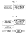
- the control apparatus of the present invention may have combustion control means for controlling the air-fuel ratio of the gas mixture supplied for combustion, the amount of fuel supplied and intake air volume, based on the result of diagnosis by the catalyst performance diagnostic means (see Fig. 2).
- the aforementioned catalyst upstream NOx volume detecting means may include a sensor, arranged upstream of the lean NOx catalyst in the emission path, for detecting the amount or concentration of NOx flowing to the NOx catalyst.
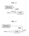
- the catalyst performance diagnostic means may be designed to diagnose the performance of the lean NOx catalyst based on the output of the sensor (see Fig. 3).
- a known NOx sensor capable of detecting the amount and concentration of the NOx in the emission gas may be used as the aforementioned sensor.
- the aforementioned catalyst upstream NOx volume detecting means may include a sensor, arranged downstream of the lean NOx catalyst in the emission path, for detecting the amount or concentration of NOx downstream from the lean NOx catalyst.
- the catalyst performance diagnostic means is designed to diagnose the performance of the lean NOx catalyst based on the output of the sensor (see Fig. 4).
- the aforementioned catalyst upstream NOx volume detecting means may include a sensor for detecting the amount or concentration of oxygen downstream from the lean NOx catalyst.
- the catalyst performance diagnostic means may be designed to diagnose the performance of the lean NOx catalyst based on the output of the sensor (see Fig. 5).
- the amount of NOx discharged from the combustion chamber or the amount of NOx flowing into the lean NOx catalyst can be indirectly detected by the NOx sensor or oxygen sensor arranged downstream from the lean NOx catalyst. This arrangement ensures high-precision diagnosis of the performance of the aforementioned lean NOx catalyst, based on the output of the sensor.
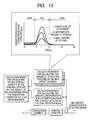
- the aforementioned catalyst performance diagnostic means may be designed to change the lean NOx catalyst deterioration evaluation level, based on the fluctuations in the amount of NOx discharged from the combustion chamber or the amount of NOx flowing into the lean NOx catalyst, detected by the catalyst upstream NOx volume detecting means (Fig. 6). To put it more specifically, when a failure has occurred to the EGR means due to the trouble of the EGR valve and there is a sudden increase in the amount of NOx flowing into the lean NOx catalyst, means may be provided to ensure that the lean NOx catalyst is not evaluated as having deteriorated, even if the amount of NOx downstream from the lean NOx catalyst has increased.
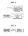
- the aforementioned catalyst performance diagnostic means may be designed to diagnose the performance of the lean NOx catalyst only when the amount of NOx detected by the catalyst upstream NOx volume detecting means lies within a predetermined range (see Fig. 7).
- the control apparatus of the present invention may comprise an EGR diagnostic means for diagnosing to see if EGR means is normal or not.
- the aforementioned catalyst performance diagnostic means may diagnose the performance of the lean NOx catalyst only when the EGR means has been evaluated as normal by the EGR diagnostic means. If there is any trouble of the EGR means, there will be a big fluctuation in the amount of NOx discharged from the combustion chamber and the amount of NOx flowing into the lean NOx catalyst, with the result that lean NOx catalyst diagnostic precision is affected. To prevent this, diagnosis of this catalyst is disabled.
- the present invention is applicable to an engine wherein lean NOx catalyst having a function of storing the NOx discharged from a combustion chamber in the lean operation mode, and desorbing and cleaning this stored NOx in the rich operation mode is provided in an exhaust path.
- This control apparatus may comprise:
- the control apparatus of the present invention may comprise means for calculating the amount of NOx discharged from the combustion chamber in the lean operation mode, in addition to the NOx storage capacity of the lean NOx catalyst, based on the results of calculations by the calculation means A and B (see Fig. 10).
- the control apparatus of the present invention may comprise:
- the estimated NOx that can be stored in the lean NOx catalyst is assumed as the reference value B.
- the concentration (or amount) downstream from the lean NOx catalyst in the lean operation mode defined by predetermined operation conditions such as torque, speed, air-fuel ratio, EGR rate and lean time
- the concentration of the estimated NOx flowing downstream without being stored in the lean NOx catalyst is assumed as the reference value A.
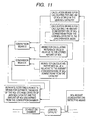
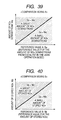
- the actual NOx concentration (or amount) downstream from the lean NOx catalyst is compared with the reference value A in the lean operation mode (comparison means A). If the actual NOx concentration (or amount) downstream from the lean NOx catalyst is smaller than the reference value A, the amount of NOx discharged from the combustion chamber is considered to have reduced. If the actual NOx concentration (or amount) downstream from the lean NOx catalyst is greater than the reference value A, the amount of NOx discharged from the combustion chamber may have increased or the NOx storage capacity of the lean NOx catalyst may have deteriorated.
- the actual amount of the NOx stored in the lean NOx catalyst is compared with the reference value B in the lean operation mode (comparison means B). If the actual amount of the NOx is greater than the reference value B, the amount of NOx discharged from the combustion chamber is evaluated to have increased. If the actual amount of the NOx is smaller than the reference value B, the amount of NOx discharged from the combustion chamber may have increased or the NOx storage capacity of the lean NOx catalyst may have deteriorated.
- Fig. 12 shows the results of comparison by the comparison means A and B shown in the form of a matrix.
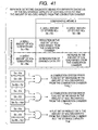
- the amount of NOx discharged from the combustion chamber is evaluated to have decreased. If the actual NOx concentration (or amount) downstream from the lean NOx catalyst is greater than the reference value A in the comparison means A during the lean operation mode, the actual NOx amount is greater than the reference value B in the comparison means B, then the amount of NOx discharged from the combustion chamber is evaluated to have increased. If the actual NOx concentration (amount) is greater than the reference value A in the comparison means A, and the actual NOx amount is smaller than the reference value B in the comparison means B, then the storage capacity of the lean NOx catalyst is evaluated to have decreased.
- the calculation means B for calculating the amount of NOx stored in the lean NOx catalyst may calculate the amount of the stored NOx, based on the output of the sensor for detecting the amount and concentration of NOx downstream from the lean NOx catalyst in the rich operation mode performed to desorb and clean the NOx stored in the lean NOx catalyst.
- Rich operation is performed to desorb and clean the NOx stored in the lean NOx catalyst in the lean operation mode.
- part of the NOx stored in the lean NOx catalyst remains unclean and is discharged downstream from the catalyst.
- the amount of discharge is proportional to the amount of NOx stored in the catalyst.
- the amount of actually stored NOx can be estimated by the amount or concentration of the NOx downstream from the lean NOx catalyst during rich operation.
- the control apparatus of the present invention may comprise a sensor for detecting the concentration of oxygen downstream from the lean NOx catalyst.
- the calculation means B for calculating the amount of NOx stored in the lean NOx catalyst may calculate the amount of the stored NOx, based on the time period from the time when air-fuel ratio of the gas mixture supplied for combustion is made rich, until the air-fuel ratio is detected as being rich by the sensor; or based on the amount of fuel injected or the amount of intake air during this time period, in the rich operation mode used to desorb and clean the NOx stored in the lean NOx catalyst.
- Rich operation is performed to desorb and clean the NOx stored in the lean operation mode.
- some time period is required from the time when air-fuel ratio of the gas mixture supplied for combustion is made rich, until the air-fuel ratio is detected as being rich by the sensor (e.g. an oxygen sensor) located downstream from the lean NOx catalyst.
- the NOx stored in the catalyst oxidizes the reducing agent (H 2 , CO, HC) flowing into the catalyst, so this time period is correlated to the amount of stored NOx.
- the amount of the actually stored NOx can be estimated based on the amount of fuel injection (or intake air volume) during this time period.
- the NOx sensor is capable of detecting oxygen at the same time, according to its principle of detection. In this case, therefore, the concentration of both NOx and oxygen can be detected by one NOx sensor.
- the control apparatus of the present invention may comprise:
- a lean NOx catalyst model is used to calculate both the amount of NOx (estimated value) stored in the lean NOx catalyst during the lean operation as the reference value B, and the amount of NOx (estimated value) discharged downstream, without being stored in the lean NOx catalyst during the lean operation as the reference value A.
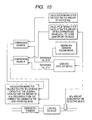
- the input value of the lean NOx catalyst model includes the amount of NOx discharged from the combustion chamber [NOx concentration at the inlet of the lean NOx catalyst (the amount of NOx flowing into the lean NOx catalyst)], air-fuel ratio of the gas mixture supplied for combustion, intake air volume and emission temperature, as shown in Fig. 16.
- the input value of the engine NOx emission volume model includes the engine torque, engine speed, and EGR rate and air-fuel ratio.
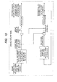
- the engine NOx emission volume model may calculate the amount of NOx discharged from the combustion chamber, by correcting the NOx emission volume basic value calculated according to the engine torque and speed, based on the EGR rate and air-fuel ratio (see Fig. 17).
- the lean NOx catalyst model may comprise:
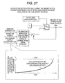
- the amount (concentration) of NOx discharged from the combustion chamber is mass-converted by the calculation means for calculating the amount of NOx flowing into the lean NOx catalyst. Then the NOx storage volume is subtracted from the amount of NOx flowing into the lean NOx catalyst to find the amount of unstored NOx. Further, the amount of NOx downstream from the catalyst is found as the reference value A by integrating the unstored amount of NOx. The amount of stored NOx is found by multiplying the amount of NOx flowing into the lean NOx catalyst, by the NOx cleaning rate or storage rate. The amount of stored NOx expresses the amount of NOx stored during a predetermined time period, and is expressed in g/T.
- the amount of NOx stored in a predetermined period time is integrated to get the total amount of NOx stored in the catalyst as a reference value B. Further, the NOx cleaning rate (storage rate) is determined according to the total amount of stored NOx (reference value B). To put it another way, this property can be expressed as follows: The greater the total amount of stored NOx, the smaller the cleaning (storage) rate.
- the control apparatus of the present invention may comprise rich control start timing setting means for setting the timing to start rich control to desorb and clean the NOx stored in the lean NOx catalyst, based on the reference value A or B (see Fig. 19).
- the timing to start rich control is determined according to the total amount of NOx stored in the catalyst as a reference value B and the amount (concentration) of NOx downstream from the catalyst as a reference value A.
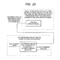
- the aforementioned rich control start timing setting means may set the timing in such a way that rich control starts when the reference value B calculated by the lean NOx catalyst model has exceeded a predetermined value B (see Fig. 20).
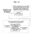
- the aforementioned rich control start timing setting means may set the timing in such a way that rich control starts when the reference value A calculated by the lean NOx catalyst model has exceeded a predetermined value Sa (see Fig. 21).
- the control apparatus of the present invention may comprise calculation means for calculating the rich volume during the rich control for desorbing and cleaning the NOx stored in the lean NOx catalyst, according to the reference value B (see Fig. 22).
- the rich volume (increase in the amount of fuel with respect to theoretical air-fuel ratio) in the rich control mode is determined according to the total amount of NOx stored in the catalyst as the reference value B. This is based on the assumption that the amount of stored NOx and the rich volume (amount of fuel) required for reduction of the stored NOx are correlated with each other.
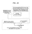
- the control apparatus of the present invention may comprise fuel supply volume calculation means for determining that the value obtained by multiplying a predetermined value C by the reference value B calculated by the lean NOx catalyst model is the fuel supply volume in the rich control mode (see Fig. 23).
- this is based on the assumption that the amount of stored NOx and the rich volume (amount of fuel) required for reduction of the stored NOx is proportional to each other.
- the control apparatus of the present invention may comprise:
- Parameters of the engine NOx emission volume model and lean NOx catalyst model may be on-line tuned, using the results of evaluation of:
- the control apparatus of the present invention may comprise means for changing the NOx emission volume basic value calculated according to the torque and speed of the engine in the engine NOx emission volume model, and the NOx emission volume correction value calculated based on the EGR rate and air-fuel ratio.
- the parameter of the engine NOx emission volume model may be on-line tuned, from the results of diagnosis in two stages - diagnosis in the lean operation mode and diagnosis in the rich operation mode, as described above.
- the position to be tuned is determined according to the torque and speed of the engine, EGR rate and air-fuel ratio in this case.
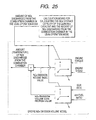
- the control apparatus of the present invention may comprise means for changing the NOx cleaning rate or storage rate calculated on the basis of the reference value B in the lean NOx catalyst, in response to the NOx storage capacity of the lean NOx catalyst (see Fig. 26).
- the parameter of the lean NOx catalyst model may be on-line tuned.
- the position to be tuned is the NOx cleaning (storing) rate calculation means.
- the relationship between the total amount of stored NOx and the NOx cleaning (storage) rate is changed in response to deterioration of the performance. To put it more specifically, the value of the NOx cleaning (storage) rate conforming to the total amount of stored NOx is reduced to show the deteriorating storage performance.
- the control apparatus of the present invention may comprise a sensor for detecting the amount or concentration of oxygen downstream from the lean NOx catalyst; and means for calculating at least one of the oxygen storage capacity of the lean NOx catalyst, NOx storage capacity of the lean NOx catalyst and the amount of NOx discharged from the combustion chamber in the lean operation mode, based on the output from the sensor.
- the lean NOx catalyst has an oxygen storage capacity, in addition to the NOx storage capacity, in some cases.
- the time period when the output of the oxygen sensor downstream from lean NOx catalyst indicates the rich air-fuel ratio includes the time when the oxygen stored in the catalyst oxidizes the reducing agent (H 2 , CO, HC) flowing in from the catalyst inlet, in addition to the time when the NOx stored in the catalyst oxidizes the reducing agent (H 2 , CO, HC) flowing in from the catalyst inlet. Therefore, this time period is correlated to both the amount of stored NOx and amount of stored oxygen, and only the amount of stored NOx cannot be detected.
- means for calculating the amount of oxygen stored in the lean NOx catalyst may be added so as to provide the function of calculating the amounts of stored NOx and oxygen, independently of each other.
- the means for calculating the amount of oxygen stored in the lean NOx catalyst calculates the amount of the stored oxygen, based on the time period from the time when air-fuel ratio of the gas mixture supplied for combustion is evaluated as being rich, until the air-fuel ratio is detected as being rich by the sensor; or based on the amount of fuel injected or the amount of intake air during this time period, in the rich operation mode used to desorb and clean the NOx stored in the lean NOx catalyst (see Fig. 28).
- the time period from the time when air-fuel ratio of the gas mixture supplied for combustion is evaluated as being rich, until the output of the rich air-fuel ratio downstream from lean NOx catalyst indicates the rich air-fuel ratio is equivalent to the time period when the NOx or oxygen stored in the catalyst oxidizes the reducing agent (H 2 , CO, HC) flowing in from the catalyst inlet.
- a fixed delay is present in the time period from the time when the rich air-fuel ratio changes into the lean air-fuel ratio until the output of the oxygen sensor downstream from lean NOx catalyst indicates the lean air-fuel ratio. This is because the oxygen flowing in from the catalyst inlet is stored in the oxygen, so an oxidation atmosphere is not created in the catalyst outlet.
- this time period depends only on the amount of stored oxygen, without depending on the amount of stored NOx. Accordingly, the amount of stored oxygen can be estimated based on the time period from the time when air-fuel ratio of the gas mixture supplied for combustion has become lean, until output of the oxygen sensor downstream from lean NOx catalyst indicates the lean air-fuel ratio. Further, to improve precision, the actual amount of stored NOx can also be estimated based on the amount of fuel injected (or intake air) during this time period.
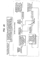
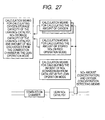
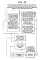
- the control apparatus of the present invention may comprise means for calculating the timing of starting the rich control to desorb and clean the NOx stored in the lean NOx catalyst and the rich volume in the rich control mode, based on at least one of the oxygen storage capacity of the lean NOx catalyst, NOx storage capacity of the lean NOx catalyst and the amount of NOx discharged from the combustion chamber in the lean operation mode (see Fig. 29).
- the amount of fuel supplied at the time of rich control includes the amount of fuel required to consume the stored oxygen in addition to the amount of fuel required for reducing the stored NOx.
- the control apparatus of the present invention is not only applicable to a spark ignition engine mounted on a vehicle but also to a compressed self-ignition engine mounted on a vehicle.
- the amount of NOx discharged is much inferior in a compressed self-ignition engine to a spark ignition engine.
- the compressed self-ignition fails, there is an increase in the amount of NOx discharged from the engine (combustion chamber). This indicates that the control apparatus of the present invention is effectively applicable to the compressed self-ignition engine as well.
- the present invention eliminates the possibility of such diagnostic error because the performance of the lean NOx catalyst is diagnosed, with consideration given to the fluctuation in the amount of NOx discharged from the combustion chamber.
- the present arrangement allows detection and diagnosis to be carried out separately, depending on whether the fluctuation is due to the increase or decrease in the amount of NOx discharged from the combustion chamber on the engine side or due to the deterioration in the performance of the lean NOx catalyst (reduction in storage capacity).
- This method eliminates the possibility of diagnostic error due to deterioration in the performance of the lean NOx catalyst, and ensures effective improvement in the performance of the emission gas of the engine and fuel economy.
- Fig. 30 is a schematic diagram representing the first embodiment of the present invention, together with an example of the car-mounted cylinder injection engine to which the same is applied.
- a cylinder injection engine 10 is a multi-cylinder engine, and includes a cylinder 12 and a piston 15 inserted slidably in the cylinder 12.
- a combustion chamber 17 is formed over this piston 15.
- the combustion chamber 17 contains an ignition plug 35 and a fuel injection valve 30 that directly injects a fuel into the combustion chamber 17.
- the fuel injection valve 30 is supplied with the fuel regulated to a predetermined pressure, by a fuel supply system equipped with a fuel tank, low pressure fuel pump, fuel pressure regulator and high pressure fuel pump (not illustrated).
- Air supplied for combustion of fuel is taken inside by an air cleaner 21 installed on the starting end of an intake path 20, and is put into a collector 27 through an air flow sensor 24 and an electronically controlled throttle valve 25. Air is then sucked into the combustion chamber 17 from this collector 27 through an intake valve 47 arranged on the downstream end of the intake path 20 (its branched path).
- a gas mixture consisting of the air sucked into the combustion chamber 17 and the fuel injected from the fuel injection valve 30 is ignited by an ignition plug 35 and is subjected to explosive combustion.
- the waste gas after combustion (emission gas) is discharged into an emission path 40 from the combustion chamber 17 through an exhaust valve 48. It flows into the lean NOx catalyst 50 arranged in the emission path 40 and is discharged to the outside after having been cleaned.
- the lean NOx catalyst 50 stores the NOx discharged from the combustion chamber 17 in the lean operation mode and rich operations performed, whereby the stored NOx catalyst is desorbed and cleaned.
- part of the emission gas discharged from the combustion chamber 17 to the emission path 40 is led to the collector 27 of the intake path 20 through an EGR path 41 as required, and is refluxed into the combustion chamber 17 of each cylinder through the branched path of the intake path 20.
- the EGR path 41 incorporates an EGR valve 42 for regulating the EGR rate.
- a control unit 100 containing various microcomputers is arranged in the control apparatus 1 of the present invention to provide various controls of the engine 10.
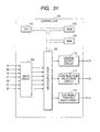
- the control unit 100 is basically composed of a CPU 101, input circuit 102, input/output port 103, RAM 104 and ROM 105, as shown in Fig. 31.
- the control unit 100 is supplied with such input signals as:
- the A/F sensor 51 has a linear output characteristics with respect to the concentration of oxygen in the emission gas.
- the relationship between concentration of oxygen in the emission gas and air-fuel ratio exhibits an almost linear form, and this allows the air-fuel ratio to be obtained from the A/F sensor 51 for detecting the oxygen concentration.
- the control unit 100 calculates the air-fuel ratio upstream from lean NOx catalyst 50 from the signal of the A/F sensor 51 and provides a F/B control of sequentially correcting the fuel injection volume or intake air volume to as to ensure that the air-fuel ratio of the gas mixture supplied for combustion reaches the level of the target air-fuel ratio.
- the NOx sensor 52 also detects oxygen concentration since it uses the principle of detecting the NOx concentration indirectly from oxygen concentration; it has the function of an oxygen-A/F sensor. Based on the signal from the NOx sensor 52, the control unit 100 calculates the concentration of NOx and oxygen, and A/F. It evaluates if there is any deterioration of the lean NOx catalyst (deterioration of storage capacity), and if there is any increase or decrease in the amount of NOx discharged from the combustion chamber 17. Thus, the control unit 100 provides the optimum control of the lean NOx catalyst 50 from the viewpoint of both the fuel economy and emission gas performance.
- the control unit 100 is supplied with the outputs from such sensors as the A/F sensor 51, throttle sensor 28, air flow sensor 28, crank angle sensor 37 and water temperature sensor 16, accelerator sensor 36, and NOx sensor 52. After noise has been removed by the input circuit 102, these signals are sent to the input/output port 103.
- the input port value is stored in the RAM 104, and is subjected to arithmetic processing in the CPU 101.
- the control program containing the description of arithmetic processing is written in the ROM 105 in advance.
- the value for the amount of each actuator operation is stored in the RAM 104 and is then sent to the input/output port 103.
- the operation signal for the ignition plug 35 is set to the ON/OFF signal that is turned on when power is supplied to the primary coil of the ignition output circuit 116, and is turned off when power is not supplied. Ignition takes place when this signal turns off.
- the signal for the ignition plug 35 set to the input/output port 103 is amplified into a sufficient energy required to ignore the ignition output circuit 116 and is sent to the ignition plug 35.
- the signal for driving the fuel injection valve 30 is set to the ON/OFF signal that is turned when the valve is on, and is turned off when the valve is off. After having been amplified into a sufficient energy required to open the fuel injection valve 30, this signal is sent to the fuel injection valve 30.
- the drive signal for achieving the opening of the target opening of the electronically controlled throttle valve 25 is sent to the electronically controlled throttle valve 25 through the electronically controlled throttle valve drive circuit 118.
- control unit 100 The following specifically describes the details of the control by the control unit 100:
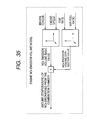
- the comparison means A if the measured amount of NOx downstream (Ma) is smaller than the reference value A (Sa), then the amount of NOx discharged from the combustion chamber 17 is evaluated as having decreased.
- the measured amount of NOx downstream (Ma) is greater than the reference value A (Sa)
- the amount of NOx discharged from the combustion chamber may have increased, or the NOx storage performance of the lean NOx catalyst may have deteriorated.
- this phase namely, from the result of comparison by comparison means A, no evaluation is made as to whether there is any increase in the amount of NOx discharged from the combustion chamber 17 or the lean NOx catalyst performance has deteriorated.
- the comparison means B if the measured amount of NOx (Mb) is greater than the reference value B (Sb), then the amount of NOx discharged from the combustion chamber 17 is evaluated as having increased.
- the measured amount of NOx (Mb) is smaller than the reference value B (Sb)
- the amount of NOx discharged from the combustion chamber 17 may have decreased, or the NOx storage performance of the lean NOx catalyst may have deteriorated.
- this phase namely, from the result of comparison by comparison means B, no evaluation is made as to whether there is any increase in the amount of NOx discharged from the combustion chamber 17 or the lean NOx catalyst performance has deteriorated.
- the lean NOx catalyst can be evaluated to have deteriorated.
- the possibility of the increase or decrease of the amount of NOx discharged from the combustion chamber in the lean operation mode can be diagnosed separately from the possibility of deterioration of the lean NOx catalyst.
- the causes of this trouble can be diagnosed separately; namely, the possibility of the increase or decrease of the amount of NOx discharged from the combustion chamber of the engine proper can be diagnosed separately from the possibility of the deterioration in the performance (storage capacity) of the lean NOx catalyst 50.
- This arrangement avoids the possible diagnostic error in the evaluation of the deterioration in the lean NOx catalyst and ensures the optimum control of the catalyst, whereby effective improvement in engine emission performance and fuel economy is provided.
- the system configuration of the second embodiment is approximately the same as that of the first embodiment (see Figs. 30, 31, 32 and 33), and will not be described here to avoid duplication.
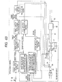
- Fig. 42 is a block diagram showing the diagnostic section for the lean NOx catalyst and the amount of NOx discharged from the combustion chamber.
- This diagnostic section is the same as that of the first embodiment (Fig. 34), except for the calculation section for calculating the amount of stored NOx (executed in the rich operation mode).
- the calculation section for calculating the amount of stored NOx calculates the amount of stored NOx by detecting the concentration of the oxygen downstream from catalyst.
- the calculation section for calculating the amount (concentration) of NOx downstream from catalyst in the lean operation mode (executed in the lean operation mode), engine NOx emission volume model, lean NOx catalyst model, comparison means A, comparison means B and separate detecting diagnostic means for separate diagnosis of the NOx storage capacity of lean NOx catalyst and the amount of NOx discharged from the combustion chamber are the same as in the first embodiment, and will not be described in details to avoid duplication.
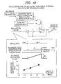
- Fig. 43 is a block diagram showing the calculation section for calculating the amount of stored NOx. Evaluation is made to see if the current mode is the rich operation mode or not. If so, Mb is assumed as the value obtained by multiplying a predetermined value by the integrated amount of the fuel injection volume during the time period Tr from the time when air-fuel ratio of the engine becomes rich, until the output of oxygen concentration, out of the output of the NOx sensor 52 downstream from lean NOx catalyst 50, becomes rich.
- This time period Tr corresponds to the time period when the NOx stored in the lean NOx catalyst 50 oxidizes the reducing agent (H 2 , CO, HC) flowing inside from the catalyst inlet. Accordingly, this is based on the fact that this time period is correlated to the amount of stored NOx.
- the lean flag in Fig. 33 is used to determine if the current mode is the rich operation mode or not.
- the system configuration of the third embodiment is approximately the same as that of the first embodiment (see Figs. 30 and 31), and will not be described here to avoid duplication.
- Fig. 44 is a diagram showing a control system of the third embodiment, and corresponds to Fig. 32 showing the first embodiment.
- the lean NOx catalyst, the amount (reference value A) of NOx downstream from the lean NOx catalyst 50 calculated by the diagnostic section for diagnosing the amount of NOx discharged from the combustion chamber, and the amount of NOx stored by the NOx catalyst are inputted into the target air-fuel ratio calculation section, and the target air-fuel ratio is calculated, based on it.
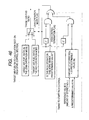
- Fig. 45 is a block diagram showing the target air-fuel ratio calculation section (the rich spike control section).
- the reference value A reference value for the amount of NOx downstream from catalyst in the lean operation mode
- the lean flag is set to "0"
- the target air-fuel ratio is set to the target air-fuel ratio for the rich operation so as to restart rich operation.
- the lean flag is set to "1”
- the target air-fuel ratio is set to the target air-fuel ratio for lean operation so as to restart lean operation.
- a predetermined value Sa should be determined in response to the permissible NOx emission volume.
- a predetermined value Sb when the reference value B (reference value for the amount of stored NOx) has exceeded a predetermined value Sb, it is possible to set the lean flag to "0" to start rich operation. This is based on the assumption that the rich operation starts when the amount of NOx stored in the NOx catalyst has exceeded a predetermined level in the lean operation mode.
- a predetermined value Sb can be determined in response to the performance of the NOx catalyst.
- the configuration other than the above is approximately the same as that of the first and second embodiments, and the description will be omitted to avoid duplication.
- the system configuration of the fourth embodiment is approximately the same as that of the first embodiment (see Figs. 30 and 31), and the control system is approximately the same as that of the second embodiment (see Fig. 44). So detailed description will be omitted to avoid duplication.
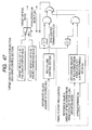
- Fig. 47 is a block diagram showing the target air-fuel ratio calculation section (rich spike control section) of the present embodiment.
- the flag is set to "0" to start rich operation. It is also possible to arrange such a configuration that, when the reference value B (reference value for the amount of stored NOx) has exceeded a predetermined level Sb, the lean flag is set to "0" to start rich operation, as shown in Fig. 46. It is also possible to arrange such a configuration that the rich control termination flag is calculated by the rich volume control section. When the rich control termination flag has indicated “1", the lean flat is set to "1" and the target air-fuel ratio is set to the target air-fuel ratio for lean operation so as to restart lean operation.
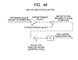
- Fig. 48 is a block diagram showing the rich volume control section.
- the value obtained by multiplying a predetermined value C by the reference value B (the amount of stored NOx) and by adding a predetermined value D thereto is assumed as the amount of fuel required to clean the stored NOx. From this value, actual fuel injection volume is subtracted for each control cycle until "0" is reached. When "0" has been reached, the rich control termination flag is set to "1". This is based on the understanding that the amount of stored NOx is proportional to the fuel volume required to clean it. For example, it is possible to terminate the rich operation when the concentration of oxygen downstream from the catalyst 50 is subjected to the reversal to the rich mode.
- feed forward control method as the one adopted in the present embodiment is preferred.
- the system configuration of the fifth embodiment is approximately the same as those of the first through fourth embodiments (see Figs. 30 and 31), and the control system is approximately the same as those of the first and second embodiments (see Figs. 32 and 44). Further, the target air-fuel ratio calculation section (rich spike control section) is also the same. Accordingly, detailed description will be omitted to avoid duplication.
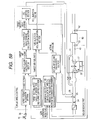
- Fig. 49 is a block diagram showing the diagnostic section for the lean NOx catalyst and the amount of NOx discharged from the combustion chamber in the present embodiment.
- the present embodiment is the same as the aforementioned embodiments, except that the parameters of the engine NOx emission volume model and lean NOx catalyst model are modified, based on the result of diagnosis by the separate detecting diagnostic section for the NOx storage capacity of the lean NOx catalyst or the amount of NOx discharged from the combustion chamber in the lean operation mode.
- the calculation section for calculating the amount of stored NOx (executed in the rich operation mode)
- the calculation section for calculating the amount (concentration) of NOx downstream from catalyst in the lean operation mode (executed in the lean operation mode)
- engine NOx emission volume model (executed in the lean operation mode)
- lean NOx catalyst model (executed in the lean operation mode)
- comparison means A comparison means B
- separate detecting diagnostic means for separate diagnosis of the NOx storage capacity of lean NOx catalyst and the amount of NOx discharged from the combustion chamber are the same as those described above, and will not be described in details to avoid duplication.
- Fig. 50 shows the specifications for changing the parameters of the engine NOx emission volume model.
- the Ma refers to the amount of downstream NOx calculated by the calculation section for calculating the amount of NOx downstream from catalyst in the lean operation mode
- the Sa indicates the reference value A calculated by the NOx catalyst model (the reference value for the amount of NOx downstream from catalyst in the lean operation mode).
- Fig. 51 shows the specifications for changing the parameter of the lean NOx catalyst model.
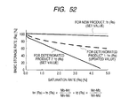
- Feat 1 according to the result of separate detection and diagnosis of the NOx storage capacity of the lean NOx catalyst shown in Fig. 41 and the amount of NOx discharged from the combustion chamber in the lean operation mode, by the separate detecting diagnostic section, this is reflected in the parameter used to obtain the basic storage rate from the saturation rate of the lean NOx catalyst model, as shown in Fig. 51.
- Fig. 52 shows the saturation rate vs. basic storage rate curves fn (Rs) and fd (Rs) for a new product and a deteriorated product 2.
- Feat 1
- the saturation rate vs. basic storage rate curves fm (Rs) for another deteriorated product 1 is obtained from the following formula.
- fm (Rs) fn (Rs) ⁇ (Mb-Md) / (Mn-Md) + fd (Rs) ⁇ (Mn-Mb) / (Mn-Md) where the Mn denotes the Mb for a new product, and Md indicates the Mb for a deteriorated product 2.
- the system configuration of the sixth embodiment is approximately the same as that of the first embodiment ( see Figs. 30 and 31), and will not be described here to avoid duplication.
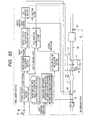
- Fig. 53 is a drawing showing a control system as a sixth embodiment in the present invention.
- the specifications for calculating the amount of oxygen stored in the lean NOx catalyst is also includes in the diagnostic section for diagnosing the lean NOx catalyst and the amount of NOx discharged from the combustion chamber.
- Fig. 54 is a block diagram showing the diagnostic section for the lean NOx catalyst and the amount of NOx discharged from the combustion chamber. It shows the same configuration as that of the first embodiment, except that the calculation section for calculating the amount of oxygen stored in the lean NOx catalyst is additionally provided.
- the calculation section for calculating the amount of stored NOx (executed in the rich operation mode), calculation section for calculating the amount (concentration) of NOx downstream from catalyst in the lean operation mode (executed in the lean operation mode), engine NOx emission volume model, lean NOx catalyst model, comparison means A, comparison means B, and separate detecting diagnostic means for separate diagnosis of the NOx storage capacity of lean NOx catalyst and the amount of NOx discharged from the combustion chamber are also the same as those described above, and will not be described in details to avoid duplication.
- Fig. 55 is a block diagram showing a calculation section for calculating the amount of stored oxygen. Evaluation is made to see whether the current mode is the lean operation mode or not. M3 is assumed as the value obtained by multiplying a predetermined value by the integrated amount of the fuel injection volume during the time period Tl from the time when air-fuel ratio of the engine becomes lean, until the output of oxygen concentration, out of the output of the NOx sensor downstream from lean NOx catalyst, becomes lean.
- This time period Tl corresponds to the time period when the oxygen flowing inside from the catalyst inlet is stored. Accordingly, this is based on the fact that this time period is correlated to the amount of stored oxygen.
- the lean flag in Fig. 33 is used to determine if the current mode is the rich operation mode or not.
- the system configuration of the seventh embodiment is approximately the same as that of the first embodiment (see Figs. 30 and 31), and will not be described here to avoid duplication.
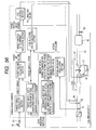
- Fig. 56 is a drawing showing a control system as a sixth embodiment in the present invention.
- the amount of NOx downstream from catalyst (reference value A) and the amount of NOx and oxygen (reference B) stored in the NOx catalyst, calculated by the diagnostic section for the lean NOx catalyst and the amount of NOx discharged from the combustion chamber are inputted into the target air-fuel ratio calculation section, and the target air-fuel ratio is calculated based thereon.
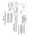
- Fig. 57 is a block diagram showing the target air-fuel ratio calculation section (rich spike mode control section).
- the lean flag is set to "0" to start rich operation. It is also possible to arrange such a configuration that, when the reference value B (reference value for the amount of stored NOx) has exceeded a predetermined level Sb, the lean flag is set to "0" to start rich operation, as shown in Fig. 46. It is also possible to arrange such a configuration that the rich control termination flag is calculated by the rich volume control section. When the rich control termination flag has indicated “1", the lean flat is set t "1" and the target air-fuel ratio is set to the target air-fuel ratio for lean operation so as to restart lean operation.
- Fig. 58 is a block diagram showing the rich volume control section.
- the value obtained by multiplying a predetermined value C by the reference value B (the amount of stored NOx) and by adding a predetermined value D thereto is assumed as the amount of fuel required to clean the stored NOx.
- the value obtained by multiplying the amount of stored oxygen by a predetermined value E and by adding a predetermined value F thereto is assumed as the amount of fuel required for the consumption of stored oxygen.
- the amount of stored NOx is proportional to the amount of fuel required to clean it
- the amount of stored oxygen is proportional to the amount of fuel required to consume it.
- feed forward control method as the one adopted in the present embodiment is preferred.
- the system configuration of the eighth embodiment is approximately the same as that of the first embodiment (see Fig. 30). However, as shown in the control system diagram in Fig. 59 and Fig. 60 (corresponding to Fig. 31 of the first embodiment), a NOx sensor 53 is added upstream from the lean NOx catalyst 50, and the output of this NOx sensor 53 is inputted into the input circuit 102.
- Fig. 61 is a block diagram showing the diagnostic section for the lean NOx catalyst and the amount of NOx discharged from the combustion chamber.
- the output of the NOx sensor 52 downstream from catalyst is inputted into the calculation section for calculating the amount of stored NOx, and the output of the NOx sensor 53 for sensing the NOx upstream from the catalyst is inputted into the calculation section for calculating the amount (concentration) of NOx downstream from catalyst in the lean operation mode.
- this embodiment is the same the first embodiment.
- Fig. 62 is a block diagram showing the calculation section for calculating the amount (concentration) of NOx upstream from catalyst in the lean operation mode. Evaluation is made to determine whether the current mode is the lean operation mode or not. If so, the amount (mass) of NOx upstream from lean NOx catalyst is calculated using the output (concentration) of the NOx sensor, intake air volume and emission temperature. Further, the amount (mass) of NOx upstream from the catalyst is integrated. The total amount (mass) of NOx discharged upstream is assumed as MAa. The MAa represents the actual measurement of the total amount (unstored) of NOx flowing out from the lean NOx catalyst in the lean operation mode. The lean flag given in Fig. 33 is used to show if the current mode is a lean mode or not.
- a sensor is used to measure the instantaneous value of the NOx concentration.
- a sensor capable of directly detecting the total amount of NOx discharged during a predetermined time period (Ma in Fig. 37 and MAa in Fig. 62).
- the system configuration of the ninth embodiment is approximately the same as that of the first embodiment (see Fig. 30). However, as shown in the control system diagram in Fig. 63 and Fig. 64 (corresponding to Fig. 31 of the first embodiment), an opening sensor 43 for detecting the opening of the EGR valve 42 is added and the output of this opening sensor 43 is inputted into the input circuit 102.
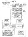
- Fig. 65 is a block diagram showing of the diagnostic section for the lean NOx catalyst and the amount of NOx discharged from the combustion chamber, and the diagnostic section of the EGR/V (valve).
- the opening of the EGR/V 42 is used to check if the EGR/V 42 is working correctly or not. If the EGR/V 42 is evaluated as working incorrectly, the diagnostic section for the lean NOx catalyst and the amount of NOx discharged from the combustion chamber is disabled. Otherwise, the configuration is the same as that of the first embodiment. Further, the diagnostic method of the EGR means including the EGR/V (valve) 42 is widely known, and will not be described in details.
- the aforementioned embodiments are all described to be applicable to the spark ignition engine. They can also be applied to the so-called compressed self-ignition engine such as a diesel engine. Especially in the compressed self-ignition engine, the amount of NOx discharged is much reduced as compared to that in the spark ignition engine. Thus, the method of diagnosing the amount of NOx discharged from the engine (combustion chamber) in the present invention is also effective in diagnosing the combustion of the compressed self-ignition engine.
Landscapes
- Engineering & Computer Science (AREA)
- Chemical & Material Sciences (AREA)
- Combustion & Propulsion (AREA)
- Mechanical Engineering (AREA)
- General Engineering & Computer Science (AREA)
- Exhaust Gas After Treatment (AREA)
- Electrical Control Of Air Or Fuel Supplied To Internal-Combustion Engine (AREA)
- Output Control And Ontrol Of Special Type Engine (AREA)
- Combined Controls Of Internal Combustion Engines (AREA)
- Exhaust-Gas Circulating Devices (AREA)
Applications Claiming Priority (2)
| Application Number | Priority Date | Filing Date | Title |
|---|---|---|---|
| JP2003320187 | 2003-09-11 | ||
| JP2003320187A JP4213548B2 (ja) | 2003-09-11 | 2003-09-11 | エンジンの制御装置 |
Publications (2)
| Publication Number | Publication Date |
|---|---|
| EP1517013A1 true EP1517013A1 (fr) | 2005-03-23 |
| EP1517013B1 EP1517013B1 (fr) | 2008-04-23 |
Family
ID=34191266
Family Applications (1)
| Application Number | Title | Priority Date | Filing Date |
|---|---|---|---|
| EP04019321A Expired - Lifetime EP1517013B1 (fr) | 2003-09-11 | 2004-08-13 | Dispositif pour le contrôle d'un moteur |
Country Status (4)
| Country | Link |
|---|---|
| US (1) | US7150144B2 (fr) |
| EP (1) | EP1517013B1 (fr) |
| JP (1) | JP4213548B2 (fr) |
| DE (1) | DE602004013243T2 (fr) |
Families Citing this family (30)
| Publication number | Priority date | Publication date | Assignee | Title |
|---|---|---|---|---|
| FR2873404B1 (fr) * | 2004-07-20 | 2006-11-17 | Peugeot Citroen Automobiles Sa | DISPOSITIF DE DETERMINATION DE LA MASSE DE NOx STOCKEE DANS UN PIEGE A NOx ET SYSTEME DE SUPERVISION DE LA REGENERATION D'UN PIEGE A NOx COMPRENANT UN TEL DISPOSITIF |
| US8286417B2 (en) * | 2005-02-03 | 2012-10-16 | Avl List Gmbh | Diagnosis method for an exhaust gas post-treatment system |
| US8215098B2 (en) * | 2005-05-02 | 2012-07-10 | Cummins Inc. | Method and apparatus for diagnosing exhaust gas aftertreatment component degradation |
| JP4215050B2 (ja) * | 2005-12-15 | 2009-01-28 | トヨタ自動車株式会社 | 内燃機関の排気浄化システム |
| US7255098B1 (en) | 2006-04-27 | 2007-08-14 | Caterpillar Inc. | Engine emissions control system |
| JP4664882B2 (ja) * | 2006-09-11 | 2011-04-06 | トヨタ自動車株式会社 | 触媒劣化診断装置 |
| DE602008001660D1 (de) * | 2008-01-29 | 2010-08-12 | Honda Motor Co Ltd | Steuersystem für einen Verbrennungsmotor |
| JP4277933B1 (ja) * | 2008-06-11 | 2009-06-10 | トヨタ自動車株式会社 | 内燃機関装置およびその制御方法並びに車両 |
| JP4576464B2 (ja) * | 2008-08-05 | 2010-11-10 | 本田技研工業株式会社 | 排ガス浄化装置の劣化判定装置 |
| JP2010185325A (ja) * | 2009-02-11 | 2010-08-26 | Denso Corp | NOx触媒の劣化診断装置 |
| US8453431B2 (en) * | 2010-03-02 | 2013-06-04 | GM Global Technology Operations LLC | Engine-out NOx virtual sensor for an internal combustion engine |
| DE102010038175A1 (de) * | 2010-10-14 | 2012-04-19 | Ford Global Technologies, Llc. | Verfahren zum Anpassen einer Mager-NOx-Falle in einem Abgassystem eines Kraftfahrzeugs |
| EP2631444B1 (fr) * | 2010-10-20 | 2016-01-13 | Toyota Jidosha Kabushiki Kaisha | Système d'évaluation de détérioration de catalyseur |
| DE102011017036B4 (de) * | 2011-04-14 | 2015-02-19 | Mtu Friedrichshafen Gmbh | Verfahren zur Regelung der NOx-Konzentration im Abgas einer Brennkraftmaschine |
| JP2013256910A (ja) * | 2012-06-13 | 2013-12-26 | Hino Motors Ltd | NOx適合装置、NOx適合方法、およびプログラム |
| GB2513614A (en) * | 2013-05-01 | 2014-11-05 | Gm Global Tech Operations Inc | Method of operating a lean NOx trap in an internal combustion engine |
| GB2541435B (en) * | 2015-08-20 | 2018-02-21 | Ford Global Tech Llc | A method of reducing NOx emissions from an engine |
| JP2019124140A (ja) * | 2018-01-12 | 2019-07-25 | 日本碍子株式会社 | 車両用エンジンにおける燃焼制御方法および車両用エンジンシステム |
| US11760170B2 (en) | 2020-08-20 | 2023-09-19 | Denso International America, Inc. | Olfaction sensor preservation systems and methods |
| US12017506B2 (en) | 2020-08-20 | 2024-06-25 | Denso International America, Inc. | Passenger cabin air control systems and methods |
| US11760169B2 (en) | 2020-08-20 | 2023-09-19 | Denso International America, Inc. | Particulate control systems and methods for olfaction sensors |
| US11932080B2 (en) | 2020-08-20 | 2024-03-19 | Denso International America, Inc. | Diagnostic and recirculation control systems and methods |
| US12251991B2 (en) | 2020-08-20 | 2025-03-18 | Denso International America, Inc. | Humidity control for olfaction sensors |
| US12269315B2 (en) | 2020-08-20 | 2025-04-08 | Denso International America, Inc. | Systems and methods for measuring and managing odor brought into rental vehicles |
| US11828210B2 (en) | 2020-08-20 | 2023-11-28 | Denso International America, Inc. | Diagnostic systems and methods of vehicles using olfaction |
| US11881093B2 (en) | 2020-08-20 | 2024-01-23 | Denso International America, Inc. | Systems and methods for identifying smoking in vehicles |
| US11636870B2 (en) | 2020-08-20 | 2023-04-25 | Denso International America, Inc. | Smoking cessation systems and methods |
| US12377711B2 (en) | 2020-08-20 | 2025-08-05 | Denso International America, Inc. | Vehicle feature control systems and methods based on smoking |
| US11813926B2 (en) | 2020-08-20 | 2023-11-14 | Denso International America, Inc. | Binding agent and olfaction sensor |
| CN116104621B (zh) * | 2023-04-10 | 2023-07-18 | 潍柴动力股份有限公司 | 氮氧化物排放控制诊断方法、装置及电子设备 |
Citations (5)
| Publication number | Priority date | Publication date | Assignee | Title |
|---|---|---|---|---|
| DE19850786A1 (de) * | 1998-08-05 | 2000-02-17 | Volkswagen Ag | Regelung eines NOx-Speicher-Katalysators |
| DE19926305A1 (de) * | 1999-06-09 | 2000-12-21 | Siemens Ag | Verfahren zur Steuerung des Betriebs eines NOx-Speicherkatalysators |
| DE10003612A1 (de) * | 2000-01-28 | 2001-08-02 | Volkswagen Ag | Verfahren und Vorrichtung zur Ermittlung einer NOx-Speicherkapazität eines NOx-Speicherkatalysators |
| EP1134376A2 (fr) * | 2000-03-17 | 2001-09-19 | Ford Global Technologies, Inc. | Méthode améliorée pour la commande d'émission de gaz d'échappement |
| DE10039709A1 (de) * | 2000-08-14 | 2002-03-07 | Bosch Gmbh Robert | Verfahren und Steuergerät zum Bestimmen des Zustands eines Stickoxid (NOx)-Speicherkatalysators |
Family Cites Families (8)
| Publication number | Priority date | Publication date | Assignee | Title |
|---|---|---|---|---|
| JP3316066B2 (ja) | 1993-12-22 | 2002-08-19 | 富士重工業株式会社 | 排気ガス浄化装置の故障診断装置 |
| DE19843879C2 (de) * | 1998-09-25 | 2003-05-08 | Bosch Gmbh Robert | Betrieb eines Verbrennungsmotors in Verbindung mit einem NOx-Speicherkatalysator und einem NOx-Sensor |
| JP4127585B2 (ja) | 1999-05-28 | 2008-07-30 | 三菱電機株式会社 | 内燃機関の排出ガス浄化装置 |
| JP3570297B2 (ja) * | 1999-06-10 | 2004-09-29 | 株式会社日立製作所 | エンジン排気浄化装置 |
| DE19942270A1 (de) * | 1999-09-04 | 2001-03-15 | Bosch Gmbh Robert | Verfahren zum Betreiben einer Brennkraftmaschine |
| DE10036453A1 (de) * | 2000-07-26 | 2002-02-14 | Bosch Gmbh Robert | Verfahren und Steuergerät zum Betreiben eines Stickoxid (NOx)-Speicherkatalysators |
| JP3775229B2 (ja) | 2001-03-08 | 2006-05-17 | トヨタ自動車株式会社 | 内燃機関の排気浄化装置 |
| JP2004162694A (ja) * | 2002-09-20 | 2004-06-10 | Mazda Motor Corp | エンジンの排気浄化装置 |
-
2003
- 2003-09-11 JP JP2003320187A patent/JP4213548B2/ja not_active Expired - Fee Related
-
2004
- 2004-08-10 US US10/914,272 patent/US7150144B2/en not_active Expired - Fee Related
- 2004-08-13 DE DE602004013243T patent/DE602004013243T2/de not_active Expired - Lifetime
- 2004-08-13 EP EP04019321A patent/EP1517013B1/fr not_active Expired - Lifetime
Patent Citations (5)
| Publication number | Priority date | Publication date | Assignee | Title |
|---|---|---|---|---|
| DE19850786A1 (de) * | 1998-08-05 | 2000-02-17 | Volkswagen Ag | Regelung eines NOx-Speicher-Katalysators |
| DE19926305A1 (de) * | 1999-06-09 | 2000-12-21 | Siemens Ag | Verfahren zur Steuerung des Betriebs eines NOx-Speicherkatalysators |
| DE10003612A1 (de) * | 2000-01-28 | 2001-08-02 | Volkswagen Ag | Verfahren und Vorrichtung zur Ermittlung einer NOx-Speicherkapazität eines NOx-Speicherkatalysators |
| EP1134376A2 (fr) * | 2000-03-17 | 2001-09-19 | Ford Global Technologies, Inc. | Méthode améliorée pour la commande d'émission de gaz d'échappement |
| DE10039709A1 (de) * | 2000-08-14 | 2002-03-07 | Bosch Gmbh Robert | Verfahren und Steuergerät zum Bestimmen des Zustands eines Stickoxid (NOx)-Speicherkatalysators |
Non-Patent Citations (1)
| Title |
|---|
| PATENT ABSTRACTS OF JAPAN vol. 1995, no. 10 30 November 1995 (1995-11-30) * |
Also Published As
| Publication number | Publication date |
|---|---|
| US20050056002A1 (en) | 2005-03-17 |
| JP2005083359A (ja) | 2005-03-31 |
| JP4213548B2 (ja) | 2009-01-21 |
| US7150144B2 (en) | 2006-12-19 |
| DE602004013243D1 (de) | 2008-06-05 |
| DE602004013243T2 (de) | 2009-06-25 |
| EP1517013B1 (fr) | 2008-04-23 |
Similar Documents
| Publication | Publication Date | Title |
|---|---|---|
| US7150144B2 (en) | Engine control apparatus | |
| EP1682759B1 (fr) | PROCEDE D'ESTIMATION DE QUANTITE D'EVACUATION DE NOx POUR MOTEUR A COMBUSTION INTERNE | |
| RU2623321C1 (ru) | Устройство диагностирования неисправности для прибора контроля выхлопных газов | |
| RU2605167C2 (ru) | Способ управления двигателем (варианты) и система двигателя | |
| EP3006689B1 (fr) | Dispositif de diagnostic d'erreur pour un dispositif de purification d'echappement | |
| US20070017212A1 (en) | Catalyst diagnosis apparatus for internal combustion engine | |
| US20100199638A1 (en) | Apparatus for diagnosing deterioration of nox absorption-reduction catalyst | |
| US10161329B2 (en) | Upstream NOx estimation | |
| JP2009221992A (ja) | 排出ガスセンサの異常診断装置 | |
| US20110290217A1 (en) | Engine system control device | |
| US7275363B2 (en) | Exhaust gas purifying apparatus and method for internal combustion engine | |
| US6826471B2 (en) | Method for determining nitrogen oxide content in internal combustion engine exhaust gases containing oxygen | |
| US10683822B2 (en) | Fuel-cetane-number estimation method and apparatus | |
| US20020029562A1 (en) | Engine exhaust purifying apparatus | |
| EP1640576B1 (fr) | Appareil et procédé d'estimation de la quantité de NOx adsorbé dans un piège à NOx | |
| JP3988518B2 (ja) | 内燃機関の排ガス浄化装置 | |
| US7096861B1 (en) | Control system for internal combustion engine | |
| JPH1172045A (ja) | 内燃機関の排気ガス再循環装置の診断方法 | |
| JP4317423B2 (ja) | エンジンの制御装置 | |
| JP2006057523A (ja) | エンジン制御システムの異常診断装置 | |
| JP4365671B2 (ja) | エンジンの制御装置 | |
| JP4403156B2 (ja) | 内燃機関の酸素センサ診断装置 | |
| JP4275046B2 (ja) | エンジンの制御装置 | |
| US7779620B2 (en) | Air-fuel ratio feedback control device | |
| JPH09125938A (ja) | エンジン制御装置 |
Legal Events
| Date | Code | Title | Description |
|---|---|---|---|
| PUAI | Public reference made under article 153(3) epc to a published international application that has entered the european phase |
Free format text: ORIGINAL CODE: 0009012 |
|
| AK | Designated contracting states |
Kind code of ref document: A1 Designated state(s): AT BE BG CH CY CZ DE DK EE ES FI FR GB GR HU IE IT LI LU MC NL PL PT RO SE SI SK TR |
|
| AX | Request for extension of the european patent |
Extension state: AL HR LT LV MK |
|
| 17P | Request for examination filed |
Effective date: 20050714 |
|
| AKX | Designation fees paid |
Designated state(s): DE FR |
|
| 17Q | First examination report despatched |
Effective date: 20050824 |
|
| 17Q | First examination report despatched |
Effective date: 20050824 |
|
| GRAP | Despatch of communication of intention to grant a patent |
Free format text: ORIGINAL CODE: EPIDOSNIGR1 |
|
| GRAS | Grant fee paid |
Free format text: ORIGINAL CODE: EPIDOSNIGR3 |
|
| GRAA | (expected) grant |
Free format text: ORIGINAL CODE: 0009210 |
|
| AK | Designated contracting states |
Kind code of ref document: B1 Designated state(s): DE FR |
|
| RAP1 | Party data changed (applicant data changed or rights of an application transferred) |
Owner name: HITACHI, LTD. |
|
| RIN1 | Information on inventor provided before grant (corrected) |
Inventor name: NAKAGAWA, SHINJI Inventor name: HORI, TOSHIO Inventor name: NAGANO, MASAMI |
|
| REF | Corresponds to: |
Ref document number: 602004013243 Country of ref document: DE Date of ref document: 20080605 Kind code of ref document: P |
|
| EN | Fr: translation not filed | ||
| PLBE | No opposition filed within time limit |
Free format text: ORIGINAL CODE: 0009261 |
|
| STAA | Information on the status of an ep patent application or granted ep patent |
Free format text: STATUS: NO OPPOSITION FILED WITHIN TIME LIMIT |
|
| 26N | No opposition filed |
Effective date: 20090126 |
|
| PG25 | Lapsed in a contracting state [announced via postgrant information from national office to epo] |
Ref country code: FR Free format text: LAPSE BECAUSE OF FAILURE TO SUBMIT A TRANSLATION OF THE DESCRIPTION OR TO PAY THE FEE WITHIN THE PRESCRIBED TIME-LIMIT Effective date: 20090227 |
|
| PGFP | Annual fee paid to national office [announced via postgrant information from national office to epo] |
Ref country code: DE Payment date: 20170808 Year of fee payment: 14 |
|
| REG | Reference to a national code |
Ref country code: DE Ref legal event code: R119 Ref document number: 602004013243 Country of ref document: DE |
|
| PG25 | Lapsed in a contracting state [announced via postgrant information from national office to epo] |
Ref country code: DE Free format text: LAPSE BECAUSE OF NON-PAYMENT OF DUE FEES Effective date: 20190301 |