EP1517098B1 - Heizkörperventil - Google Patents
Heizkörperventil Download PDFInfo
- Publication number
- EP1517098B1 EP1517098B1 EP04090332.0A EP04090332A EP1517098B1 EP 1517098 B1 EP1517098 B1 EP 1517098B1 EP 04090332 A EP04090332 A EP 04090332A EP 1517098 B1 EP1517098 B1 EP 1517098B1
- Authority
- EP
- European Patent Office
- Prior art keywords
- valve
- cap
- radiator
- radiator valve
- casing
- Prior art date
- Legal status (The legal status is an assumption and is not a legal conclusion. Google has not performed a legal analysis and makes no representation as to the accuracy of the status listed.)
- Expired - Lifetime
Links
Images
Classifications
-
- F—MECHANICAL ENGINEERING; LIGHTING; HEATING; WEAPONS; BLASTING
- F24—HEATING; RANGES; VENTILATING
- F24D—DOMESTIC- OR SPACE-HEATING SYSTEMS, e.g. CENTRAL HEATING SYSTEMS; DOMESTIC HOT-WATER SUPPLY SYSTEMS; ELEMENTS OR COMPONENTS THEREFOR
- F24D19/00—Details
- F24D19/0002—Means for connecting central heating radiators to circulation pipes
-
- F—MECHANICAL ENGINEERING; LIGHTING; HEATING; WEAPONS; BLASTING
- F16—ENGINEERING ELEMENTS AND UNITS; GENERAL MEASURES FOR PRODUCING AND MAINTAINING EFFECTIVE FUNCTIONING OF MACHINES OR INSTALLATIONS; THERMAL INSULATION IN GENERAL
- F16K—VALVES; TAPS; COCKS; ACTUATING-FLOATS; DEVICES FOR VENTING OR AERATING
- F16K27/00—Construction of housing; Use of materials therefor
- F16K27/12—Covers for housings
-
- F—MECHANICAL ENGINEERING; LIGHTING; HEATING; WEAPONS; BLASTING
- F24—HEATING; RANGES; VENTILATING
- F24D—DOMESTIC- OR SPACE-HEATING SYSTEMS, e.g. CENTRAL HEATING SYSTEMS; DOMESTIC HOT-WATER SUPPLY SYSTEMS; ELEMENTS OR COMPONENTS THEREFOR
- F24D19/00—Details
- F24D19/10—Arrangement or mounting of control or safety devices
- F24D19/1006—Arrangement or mounting of control or safety devices for water heating systems
- F24D19/1009—Arrangement or mounting of control or safety devices for water heating systems for central heating
- F24D19/1015—Arrangement or mounting of control or safety devices for water heating systems for central heating using a valve or valves
Definitions
- the invention relates to a radiator valve according to the preamble of claim 1, with a valve housing which is provided at the periphery with a screw thread, a torque application surface and a mounting geometry for a protective cap, wherein the protective cap protruding from an end face of the valve housing, for valve regulation by a Thermostatic head provided, valve pin covers.
- the radiator valve is screwed with the screw thread in a radiator.
- the radiator is then transported with screwed valve to the site and mounted there.
- the valve inserts are provided with a protective cap to protect the valve rod protruding from the valve housing valve pin from damage.
- the valve inserts screwed into a valve body are provided with a protective cap up to their equipment with a thermostatic head, so that damage to the valve pin can be avoided in rough construction operation.
- Such protective caps are indispensable, but they often increase the assembly effort, because after mounting the radiator valve assembly of the cap is required. To ensure a uniform mass flow, it is further necessary to preset the valve inserts. Such a presetting causes a limitation of the maximum opening width of the valve core.
- Another radiator valve is out of the DE 101 27 855 A1 known, which shows the preamble of claim 1.
- the support wall is deformed at an axial force introduction, so that via the valve pin, the optionally destructive force can act on the valve seat.
- the invention is therefore based on the object to propose a radiator valve, which improves the known from the prior art solutions, in particular, the functionality and protective effect of the cap should be preserved.
- the invention includes a radiator valve of the type mentioned, wherein the protective cap consists of an outer cover sleeve and an inner cap, which are interconnected by webs, wherein the bottom of the outer cover sleeve through the webs having separate openings.
- the protective cap is preferably formed in one piece and has a substantially cylindrical outer shape, wherein the bottom of the outer cover sleeve is broken twice. Through these two openings, a screw can be placed on the existing torque application surface of the valve core.
- valve core and cap can be done independently of time or prior to installation in the radiator.
- the assembly of valve insert and protective cap to the preassembled unit is preferably already carried out during manufacture of the valve inserts as an additional, automatable production step.
- the edge of the outer cover sleeve lying in the screwing-in direction is advantageously provided with an internal thread which cooperates with the fastening geometry on the valve housing.
- the edge of the inner cap lying in the screwing-in direction is directed against the torque application surface, wherein the bottom of the inner cap has a cup-shaped design for cooperation with the valve pin.
- the bottom of the inner cap presses therefore the valve pin with screwed cap in the valve core.
- the outer cover sleeve and the inner cap are spaced apart from one another via the webs in such a way that a screw means can be introduced to the torque application surface in the forming gap.
- the inventive solution of the cap offers advantages, since the protective effect remains high in the radial direction against dirt or force.
- the protective effect in the axial direction is substantially increased by the fact that the bottom of the inner cap is offset relative to the edge of the cap inwardly towards the valve insert, and at a corresponding axial force first deforms the outer sleeve of the cap and the webs are deformed ,
- the inner cap is supported on the valve set and thus prevents an introduction of force via the valve pin and the valve seat, which could lead to destruction of the valve core.
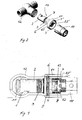
- radiator valve 1 An Indian FIG. 1 shown in section radiator valve 1 is screwed with a male thread 3, which is located on its housing 2 in a radiator fitting 12.
- screwing screwing means 10 preferably a slotted socket wrench on the radiator valve. 1 fitted and comes with the housing 2 formed on the torque application surface 4 into engagement.
- an actuating device in the form of a valve pin 9 is further provided, which serves in a conventional manner for actuating the valve.
- the valve pin 9 is displaceable in the axial direction with respect to the screwing-in direction of the external thread 3 and is to be protected from external mechanical influences and stresses by a protective cap 6.
- the protective cap 6 is fastened to a fastening geometry 5 provided on the valve housing 2, thereby covering the valve pin 9 projecting from an end face of the valve housing 2.
- the protective cap 6 is formed integrally here and has a substantially cylindrical outer shape. It consists of an outer cover sleeve 61 and an inner cap 62, which are connected via webs 8, 8 'with each other. The bottom of the outer cover sleeve 61 has through the webs 8, 8 'separate openings 7, 7'. Through these two openings 7,7 ', the screw 10, preferably a slotted socket wrench can be placed on the existing torque application surface 4 of the valve core. The edge of the inner cap 62 in the screwing direction is directed against the torque application surface 4, wherein the bottom of the inner cap 62 has a cup-shaped formation 63 for cooperation with the valve pin 9.
- valve insert 1 and protective cap 6 to a preassembled unit 13 is already carried out during manufacture of the valve inserts as an additional, automatable production step.
Landscapes
- Engineering & Computer Science (AREA)
- General Engineering & Computer Science (AREA)
- Mechanical Engineering (AREA)
- Physics & Mathematics (AREA)
- Thermal Sciences (AREA)
- Chemical & Material Sciences (AREA)
- Combustion & Propulsion (AREA)
- Valve Housings (AREA)
Description
- Die Erfindung betrifft ein Heizkörperventil nach dem Oberbegriff des Anspruchs 1, mit einem Ventilgehäuse, welches am Umfang mit einem Einschraubgewinde, einer Drehmomentenangriffsfläche und einer Befestigungsgeometrie für eine Schutzkappe versehen ist, wobei die Schutzkappe einen aus einer Stirnseite des Ventilgehäuses herausragenden, für die Ventilregulierung durch einen Thermostatkopf vorgesehenen, Ventilstift abdeckt.
- Das Heizkörperventil wird mit dem Einschraubgewinde in einen Heizkörper eingeschraubt. Der Heizkörper wird dann mit eingeschraubtem Ventil zur Baustelle transportiert und dort montiert. Die Ventileinsätze werden mit einer Schutzkappe versehen, um den aus dem Ventilgehäuse herausragenden hubstangenartigen Ventilstift vor Beschädigungen zu schützen. Weiter werden die in einen Ventilkörper eingeschraubten Ventileinsätze bis zu deren Ausstattung mit einem Thermostatkopf mit einer Schutzkappe versehen, damit im rauen Baubetrieb Beschädigungen des Ventilstiftes vermieden werden. Derartige Schutzkappen sind unentbehrlich, sie erhöhen aber oft den Montageaufwand, weil nach dem Montieren des Heizkörperventils die Montage der Schutzkappe erforderlich ist.
Zur Gewährleistung eines einheitlichen Massenstromes ist es weiter notwendig die Ventileinsätze voreinzustellen. Eine derartige Voreinstellung bewirkt eine Begrenzung der maximalen Öffnungsweite des Ventileinsatzes. Zum Einstellen einer solchen Voreinstellung ist koaxial zum Ventilstift ein um die Achse des Ventilstifts drehbares Einstellelement vorgesehen. Durch Drehen dieses Einstellelementes erfolgt dann eine Begrenzung des Durchflusses. Zum Betätigen des Einstellelementes ist bekannt, dieses mit einer Aufnahme zum Einsatz eines Werkzeuges auszustatten. Aus dem Stand der Technik sind dazu eine Vielzahl von Lösungen bekannt.
In derDE 197 39 109 C2 wird ein Heizkörperventil der eingangs genannten Art beschrieben. Dieses ist dadurch gekennzeichnet, dass die Drehmomentenangriffsfläche bezogen auf die Einschraubrichtung radial über die Schutzkappe vorsteht. Mit dieser Ausbildung wird es zwar möglich, dass man ein Heizkörperventil mit vormontierter Schutzkappe am Heizkörper montieren kann, die Drehmomentenangriffsfläche wird jedoch nicht von der Schutzkappe abgedeckt und ist somit vor Beschädigungen nicht geschützt. - Ein weiteres Heizkörperventil ist aus der
DE 101 27 855 A1 bekannt, die den Oberbegriff von Anspruch 1 zeigt. Hier wird bei einer axialen Krafteinleitung die Unterstützungswand verformt, so dass über den Ventilstift die gegebenenfalls das Ventil zerstörende Kraft auf den Ventilsitz wirken kann. - Der Erfindung liegt von daher die Aufgabe zugrunde ein Heizkörperventil vorzuschlagen, welches die aus dem Stand der Technik bekannten Lösungen verbessert, wobei insbesondere die Funktionalität und Schutzwirkung der Schutzkappe erhalten bleiben soll.
- Erfindungsgemäß wird diese Aufgabe durch die Merkmale des Anspruchs 1 gelöst. Vorteilhafte Weiterbildungen der Erfindung sind in den zugehörigen Ansprüchen enthalten.
- Demnach beinhaltet die Erfindung ein Heizkörperventil der eingangs genannten Art, wobei die Schutzkappe aus einer äußeren Abdeckhülse und einer inneren Kappe besteht, die über Stege miteinander verbunden sind, wobei der Boden der äußeren Abdeckhülse durch die Stege voneinander getrennte Öffnungen aufweist. Die Schutzkappe ist vorzugsweise einstückig ausgebildet ist und weist eine im Wesentlichen zylindrische Außenform auf, wobei der Boden der äußeren Abdeckhülse zweimal aufgebrochen ist. Durch diese beiden Öffnungen kann ein Schraubmittel auf die vorhandene Drehmomentenangriffsfläche des Ventileinsatzes aufgesetzt werden.
- Somit kann die Montage von Ventileinsatz und Schutzkappe zeitlich unabhängig von der bzw. vor der Montage in den Heizkörper erfolgen. Vorzugsweise wird die Montage von Ventileinsatz und Schutzkappe zu der vormontierten Einheit bereits beim Herstellen der Ventileinsätze als zusätzlicher, automatisierbarer Fertigungsschritt erfolgen.
- Vorteilhaft ist der in Einschraubrichtung liegende Rand der äußeren Abdeckhülse mit einem Innengewinde versehen, welches mit der Befestigungsgeometrie am Ventilgehäuse zusammenwirkt.
- Nach einem weiteren Merkmal ist der in Einschraubrichtung liegende Rand der inneren Kappe gegen die Drehmomentenangriffsfläche gerichtet, wobei der Boden der inneren Kappe eine topfförmige Ausbildung für das Zusammenwirken mit dem Ventilstift aufweist. Der Boden der inneren Kappe drückt demnach den Ventilstift bei aufgeschraubter Schutzkappe in den Ventileinsatz. Über ein Auf- bzw. Zudrehen der Schutzkappe kann somit ein Probebetrieb auf der Baustelle erfolgen.
- Vorteilhaft sind die äußere Abdeckhülse und die innere Kappe über die Stege derart voneinander beabstandet, dass in dem sich bildenden Spalt ein Schraubmittel an die Drehmomentenangriffsfläche einbringbar ist.
- Insbesondere bei Lagerung und Transport bietet die erfindungsgemäße Lösung der Schutzkappe Vorteile, da die Schutzwirkung in radialer Richtung gegen Schmutz oder Krafteinwirkung unverändert hoch bleibt. Die Schutzwirkung in axialer Richtung wird aber wesentlich erhöht und zwar dadurch, dass der Boden der inneren Kappe bezogen zum Rand der Schutzkappe nach innen in Richtung Ventileinsatz versetzt ist, und bei einer entsprechenden axialen Krafteinwirkung zuerst die äußere Hülse der Schutzkappe deformiert und die Stege verformt werden. Die innere Kappe stützt sich aber am Ventilsatz ab und verhindert somit eine Krafteinleitung über den Ventilstift und den Ventilsitz, was zu einer Zerstörung des Ventileinsatzes führen könnte.
- Weitere Vorteile der Erfindung ergeben sich aus der nachfolgenden Beschreibung eines Ausführungsbeispieles. In den Zeichnungen zeigen
- Figur 1:
- einen schematischen Querschnitt durch ein Heizkörperventil mit aufgesetzter Schutzkappe und Montagewerkzeug,
- Figur 2:
- eine perspektivische Darstellung von Schutzkappe und Ventil als eine vormontierte Einheit.
- Ein in der
Figur 1 im Schnitt dargestelltes Heizkörperventil 1 ist mit einem Außengewinde 3, das sich an seinem Gehäuse 2 befindet in einen Heizkörperfitting 12 eingeschraubt. Zum Einschrauben wird Schraubmittel 10, vorzugsweise ein geschlitzter Steckschlüssel auf das Heizkörperventil 1 aufgesteckt und kommt dabei mit der am Gehäuse 2 ausgebildeten Drehmomentenangriffsfläche 4 in Eingriff. Im Heizkörperventil 1 ist weiter eine Betätigungseinrichtung in Form eines Ventilstiftes 9 vorgesehen, der in an sich bekannter Weise zur Betätigung des Ventils dient. Der Ventilstift 9 ist in Axialrichtung bezogen auf die Einschraubrichtung des Außengewindes 3 verschiebbar und soll vor äußeren mechanischen Einwirkungen und Belastungen von einer Schutzkappe 6 geschützt werden. Die Schutzkappe 6 ist dazu an einer am Ventilgehäuse 2 vorgesehenen Befestigungsgeometrie 5 befestigt und deckt dabei den aus einer Stirnseite des Ventilgehäuses 2 herausragenden Ventilstift 9 ab. Die Schutzkappe 6 ist hier einstückig ausgebildet und weist eine im Wesentlichen zylindrische Außenform auf. Sie besteht aus einer äußeren Abdeckhülse 61 und einer inneren Kappe 62, die über Stege 8, 8'miteinander verbunden sind. Der Boden der äußeren Abdeckhülse 61 weist durch die Stege 8, 8' voneinander getrennte Öffnungen 7, 7'auf. Durch diese beiden Öffnungen 7,7' kann das Schraubmittel 10, vorzugsweise ein geschlitzter Steckschlüssel auf die vorhandene Drehmomentenangriffsfläche 4 des Ventileinsatzes aufgesetzt werden. Der in Einschraubrichtung liegende Rand der inneren Kappe 62 ist gegen die Drehmomentenangriffsfläche 4 gerichtet, wobei der Boden der inneren Kappe 62 eine topfförmige Ausbildung 63 für das Zusammenwirken mit dem Ventilstift 9 aufweist. Der Boden der inneren Kappe 62 drückt demnach den Ventilstift 9 bei aufgeschraubter Schutzkappe 6 in den Ventileinsatz. Über ein Auf- bzw. Zudrehen der Schutzkappe 6 kann somit ein Probebetrieb auf der Baustelle erfolgen.
Vorzugsweise wird die Montage von Ventileinsatz 1 und Schutzkappe 6 zu einer vormontierten Einheit 13 bereits beim Herstellen der Ventileinsätze als zusätzlicher, automatisierbarer Fertigungsschritt vorgenommen. -
- 1
- Heizkörperventil
- 2
- Ventilgehäuse
- 3
- Außengewinde
- 4
- Drehmomentenangriffsfläche
- 5
- Befestigungsgeometrie
- 6
- Schutzkappe
- 61
- äußere Abdeckhülse
- 62
- innere Kappe
- 63
- topfförmige Ausbildung
- 7,7'
- Öffnungen
- 8,8'
- Stege
- 9
- Ventilstift
- 10
- Schraubmittel
- 11
- Ventilsitz
- 12
- Heizkörperfitting
- 13
- vormontierten Einheit
Claims (6)
- Heizkörperventil mit einem Ventilgehäuse, welches am Umfang mit einem Einschraubgewinde, einer Drehmomentenangriffsfläche und einer Befestigungsgeometrie für eine Schutzkappe versehen ist, wobei die Schutzkappe einen aus einer Stirnseite des Ventilgehäuses herausragenden Ventilstift abdeckt, dadurch gekennzeichnet, dass die Schutzkappe (6) aus einer äußeren Abdeckhülse (61) und einer inneren Kappe (62) besteht, die über Stege (8, 8') miteinander verbunden sind, wobei der Boden der äußeren Abdeckhülse (61) durch die Stege (8, 8') voneinander getrennte Öffnungen (7, 7') aufweist.
- Heizkörperventil nach Anspruch 1, dadurch gekennzeichnet, dass der in Einschraubrichtung liegende Rand der äußeren Abdeckhülse (61) mit einem Innengewinde versehen ist, welches mit der Befestigungsgeometrie (5) am Ventilgehäuse (2) zusammenwirkt.
- Heizkörperventil nach den Ansprüchen 1 und 2, dadurch gekennzeichnet, dass der in Einschraubrichtung liegende Rand der inneren Kappe (62) gegen die Drehmomentenangriffsfläche (4) gerichtet ist, und der Boden der inneren Kappe (62) eine topfförmige Ausbildung (63) für das Zusammenwirken mit dem Ventilstift (9) aufweist.
- Heizkörperventil nach den Ansprüchen 1 bis 3, dadurch gekennzeichnet, dass der Boden der inneren Kappe (62) bei aufgeschraubter Schutzkappe (6) den Ventilstift (9) beaufschlagt.
- Heizkörperventil nach den Ansprüchen 1 bis 4, dadurch gekennzeichnet, dass die Schutzkappe einstückig ausgebildet ist und eine im Wesentlichen zylindrische Außenform aufweist.
- Heizkörperventil nach den Ansprüchen 1 bis 5, dadurch gekennzeichnet, dass die Schutzkappe (6) und das Ventil (1) eine vormontierte Einheit (13) bilden.
Priority Applications (1)
| Application Number | Priority Date | Filing Date | Title |
|---|---|---|---|
| PL04090332T PL1517098T3 (pl) | 2003-09-17 | 2004-08-27 | Zawór grzejnikowy |
Applications Claiming Priority (2)
| Application Number | Priority Date | Filing Date | Title |
|---|---|---|---|
| DE10343269 | 2003-09-17 | ||
| DE10343269A DE10343269A1 (de) | 2003-09-17 | 2003-09-17 | Heizkörperventil |
Publications (2)
| Publication Number | Publication Date |
|---|---|
| EP1517098A1 EP1517098A1 (de) | 2005-03-23 |
| EP1517098B1 true EP1517098B1 (de) | 2014-10-15 |
Family
ID=34177817
Family Applications (1)
| Application Number | Title | Priority Date | Filing Date |
|---|---|---|---|
| EP04090332.0A Expired - Lifetime EP1517098B1 (de) | 2003-09-17 | 2004-08-27 | Heizkörperventil |
Country Status (3)
| Country | Link |
|---|---|
| EP (1) | EP1517098B1 (de) |
| DE (1) | DE10343269A1 (de) |
| PL (1) | PL1517098T3 (de) |
Families Citing this family (2)
| Publication number | Priority date | Publication date | Assignee | Title |
|---|---|---|---|---|
| GB2424054A (en) * | 2005-03-19 | 2006-09-13 | James Patrick O'neill | Safety cover for radiator valve |
| DE102021109708A1 (de) | 2021-04-16 | 2022-10-20 | Maik Benschig | Montagehilfe für die montage von thermostat-ventilunterteilen |
Family Cites Families (5)
| Publication number | Priority date | Publication date | Assignee | Title |
|---|---|---|---|---|
| DE19739109C2 (de) * | 1997-09-06 | 2000-04-20 | Danfoss As | Heizkörperventil |
| US5823023A (en) * | 1997-10-29 | 1998-10-20 | Brady Usa, Inc. | Locking device for a valve |
| DE19830307C2 (de) * | 1998-07-07 | 2003-07-03 | Heimeier Gmbh Metall Theodor | Heizkörperventil für Heizungsanlagen |
| DE10119588C1 (de) * | 2001-04-21 | 2003-02-13 | Danfoss As | Ventil |
| DE10127855B4 (de) * | 2001-06-08 | 2005-01-20 | Danfoss A/S | Heizkörperventil |
-
2003
- 2003-09-17 DE DE10343269A patent/DE10343269A1/de not_active Withdrawn
-
2004
- 2004-08-27 EP EP04090332.0A patent/EP1517098B1/de not_active Expired - Lifetime
- 2004-08-27 PL PL04090332T patent/PL1517098T3/pl unknown
Also Published As
| Publication number | Publication date |
|---|---|
| DE10343269A1 (de) | 2005-04-21 |
| EP1517098A1 (de) | 2005-03-23 |
| PL1517098T3 (pl) | 2015-03-31 |
Similar Documents
| Publication | Publication Date | Title |
|---|---|---|
| EP2715201B1 (de) | Kombination aus einem kunststoffschlauch für laborgeräte und einem schraubelement | |
| WO2012041303A2 (de) | Kabelverschraubung bzw. kabelfixierung mit integrierter kabelzugentlastung | |
| DE3236372A1 (de) | Thermostataufsatz fuer ein ventil | |
| DE4442075C1 (de) | Schraubverbindung | |
| EP2183509B1 (de) | Vorrichtung zur drosselung des freien querschnittes einer dampfleitung oder dergleichen | |
| EP3347607A1 (de) | Schutzkappe, kugelgelenk mit einer solchen schutzkappe und zweipunktlenker mit einem derartigen kugelgelenk | |
| DE102009033711B4 (de) | Überströmventil | |
| EP1517098B1 (de) | Heizkörperventil | |
| DE102005051226A1 (de) | Kabel- oder Schlauchverschraubung | |
| EP1895210B1 (de) | Motorgetriebenes Ventil | |
| DE10153988B4 (de) | Sollwerteinstellvorrichtung an einem thermostatisch geregelten Mischventil | |
| DE19627952C2 (de) | Zündkerze für eine Brennkraftmaschine und zugehöriges Werkzeug | |
| DE102013101678B3 (de) | Sicherheitsventil | |
| DE102013101677B4 (de) | Sicherheitsventil | |
| EP1212563A1 (de) | Einbauventil für einen gliederheizkörper | |
| EP2265831B1 (de) | Schraubteil für eine befestigung einer felge eines kraftfahrzeugs | |
| DE19510169A1 (de) | Futter mit Kupplung | |
| DE20120432U1 (de) | Schraubverschluss für Flüssigkeitsbehälter, insbesondere einer Ölwanne für Kraftfahrzeuge | |
| DE10119589C1 (de) | Ventil, insbesondere Thermostatventil für Heizungsanlagen | |
| DE19732885B4 (de) | Verschlussdeckel mit Sicherheitsverriegelung für einen Behälter | |
| DE29905980U1 (de) | Verschluß für einen Dampfbehälter | |
| EP1273793B1 (de) | Schraubsicherung zur Drehblockierung eines Schraubteils | |
| EP3537017A1 (de) | Ventil | |
| EP0746713B1 (de) | Hydraulisches einsatzventil | |
| EP2226541B1 (de) | Betätigungsanordnung für Sanitärarmaturen |
Legal Events
| Date | Code | Title | Description |
|---|---|---|---|
| PUAI | Public reference made under article 153(3) epc to a published international application that has entered the european phase |
Free format text: ORIGINAL CODE: 0009012 |
|
| AK | Designated contracting states |
Kind code of ref document: A1 Designated state(s): AT BE BG CH CY CZ DE DK EE ES FI FR GB GR HU IE IT LI LU MC NL PL PT RO SE SI SK TR |
|
| AX | Request for extension of the european patent |
Extension state: AL HR LT LV MK |
|
| 17P | Request for examination filed |
Effective date: 20050722 |
|
| AKX | Designation fees paid |
Designated state(s): AT BE BG CH CY CZ DE DK EE ES FI FR GB GR HU IE IT LI LU MC NL PL PT RO SE SI SK TR |
|
| 17Q | First examination report despatched |
Effective date: 20070213 |
|
| REG | Reference to a national code |
Ref country code: DE Ref legal event code: R079 Ref document number: 502004014739 Country of ref document: DE Free format text: PREVIOUS MAIN CLASS: F24D0019100000 Ipc: F24D0019000000 |
|
| RIC1 | Information provided on ipc code assigned before grant |
Ipc: F24D 19/10 20060101ALI20130617BHEP Ipc: F24D 19/00 20060101AFI20130617BHEP Ipc: F16K 27/12 20060101ALI20130617BHEP |
|
| GRAP | Despatch of communication of intention to grant a patent |
Free format text: ORIGINAL CODE: EPIDOSNIGR1 |
|
| INTG | Intention to grant announced |
Effective date: 20140502 |
|
| GRAS | Grant fee paid |
Free format text: ORIGINAL CODE: EPIDOSNIGR3 |
|
| GRAA | (expected) grant |
Free format text: ORIGINAL CODE: 0009210 |
|
| AK | Designated contracting states |
Kind code of ref document: B1 Designated state(s): AT BE BG CH CY CZ DE DK EE ES FI FR GB GR HU IE IT LI LU MC NL PL PT RO SE SI SK TR |
|
| REG | Reference to a national code |
Ref country code: CH Ref legal event code: EP Ref country code: GB Ref legal event code: FG4D Free format text: NOT ENGLISH |
|
| REG | Reference to a national code |
Ref country code: CH Ref legal event code: NV Representative=s name: PATENTANWALT DIPL.-ING. (UNI.) WOLFGANG HEISEL, CH |
|
| REG | Reference to a national code |
Ref country code: IE Ref legal event code: FG4D Free format text: LANGUAGE OF EP DOCUMENT: GERMAN |
|
| REG | Reference to a national code |
Ref country code: AT Ref legal event code: REF Ref document number: 691868 Country of ref document: AT Kind code of ref document: T Effective date: 20141115 |
|
| REG | Reference to a national code |
Ref country code: DE Ref legal event code: R096 Ref document number: 502004014739 Country of ref document: DE Effective date: 20141127 |
|
| REG | Reference to a national code |
Ref country code: NL Ref legal event code: VDEP Effective date: 20141015 |
|
| PG25 | Lapsed in a contracting state [announced via postgrant information from national office to epo] |
Ref country code: NL Free format text: LAPSE BECAUSE OF FAILURE TO SUBMIT A TRANSLATION OF THE DESCRIPTION OR TO PAY THE FEE WITHIN THE PRESCRIBED TIME-LIMIT Effective date: 20141015 |
|
| REG | Reference to a national code |
Ref country code: PL Ref legal event code: T3 |
|
| PG25 | Lapsed in a contracting state [announced via postgrant information from national office to epo] |
Ref country code: PT Free format text: LAPSE BECAUSE OF FAILURE TO SUBMIT A TRANSLATION OF THE DESCRIPTION OR TO PAY THE FEE WITHIN THE PRESCRIBED TIME-LIMIT Effective date: 20150216 Ref country code: ES Free format text: LAPSE BECAUSE OF FAILURE TO SUBMIT A TRANSLATION OF THE DESCRIPTION OR TO PAY THE FEE WITHIN THE PRESCRIBED TIME-LIMIT Effective date: 20141015 |
|
| PG25 | Lapsed in a contracting state [announced via postgrant information from national office to epo] |
Ref country code: GR Free format text: LAPSE BECAUSE OF FAILURE TO SUBMIT A TRANSLATION OF THE DESCRIPTION OR TO PAY THE FEE WITHIN THE PRESCRIBED TIME-LIMIT Effective date: 20150116 Ref country code: CY Free format text: LAPSE BECAUSE OF FAILURE TO SUBMIT A TRANSLATION OF THE DESCRIPTION OR TO PAY THE FEE WITHIN THE PRESCRIBED TIME-LIMIT Effective date: 20141015 Ref country code: SE Free format text: LAPSE BECAUSE OF FAILURE TO SUBMIT A TRANSLATION OF THE DESCRIPTION OR TO PAY THE FEE WITHIN THE PRESCRIBED TIME-LIMIT Effective date: 20141015 |
|
| REG | Reference to a national code |
Ref country code: DE Ref legal event code: R097 Ref document number: 502004014739 Country of ref document: DE |
|
| PG25 | Lapsed in a contracting state [announced via postgrant information from national office to epo] |
Ref country code: RO Free format text: LAPSE BECAUSE OF FAILURE TO SUBMIT A TRANSLATION OF THE DESCRIPTION OR TO PAY THE FEE WITHIN THE PRESCRIBED TIME-LIMIT Effective date: 20141015 Ref country code: SK Free format text: LAPSE BECAUSE OF FAILURE TO SUBMIT A TRANSLATION OF THE DESCRIPTION OR TO PAY THE FEE WITHIN THE PRESCRIBED TIME-LIMIT Effective date: 20141015 Ref country code: EE Free format text: LAPSE BECAUSE OF FAILURE TO SUBMIT A TRANSLATION OF THE DESCRIPTION OR TO PAY THE FEE WITHIN THE PRESCRIBED TIME-LIMIT Effective date: 20141015 Ref country code: DK Free format text: LAPSE BECAUSE OF FAILURE TO SUBMIT A TRANSLATION OF THE DESCRIPTION OR TO PAY THE FEE WITHIN THE PRESCRIBED TIME-LIMIT Effective date: 20141015 |
|
| PLBE | No opposition filed within time limit |
Free format text: ORIGINAL CODE: 0009261 |
|
| STAA | Information on the status of an ep patent application or granted ep patent |
Free format text: STATUS: NO OPPOSITION FILED WITHIN TIME LIMIT |
|
| 26N | No opposition filed |
Effective date: 20150716 |
|
| PGFP | Annual fee paid to national office [announced via postgrant information from national office to epo] |
Ref country code: CH Payment date: 20150819 Year of fee payment: 12 |
|
| PGFP | Annual fee paid to national office [announced via postgrant information from national office to epo] |
Ref country code: AT Payment date: 20150820 Year of fee payment: 12 |
|
| PG25 | Lapsed in a contracting state [announced via postgrant information from national office to epo] |
Ref country code: SI Free format text: LAPSE BECAUSE OF FAILURE TO SUBMIT A TRANSLATION OF THE DESCRIPTION OR TO PAY THE FEE WITHIN THE PRESCRIBED TIME-LIMIT Effective date: 20141015 |
|
| PG25 | Lapsed in a contracting state [announced via postgrant information from national office to epo] |
Ref country code: LU Free format text: LAPSE BECAUSE OF FAILURE TO SUBMIT A TRANSLATION OF THE DESCRIPTION OR TO PAY THE FEE WITHIN THE PRESCRIBED TIME-LIMIT Effective date: 20150827 Ref country code: MC Free format text: LAPSE BECAUSE OF FAILURE TO SUBMIT A TRANSLATION OF THE DESCRIPTION OR TO PAY THE FEE WITHIN THE PRESCRIBED TIME-LIMIT Effective date: 20141015 |
|
| REG | Reference to a national code |
Ref country code: IE Ref legal event code: MM4A |
|
| PG25 | Lapsed in a contracting state [announced via postgrant information from national office to epo] |
Ref country code: IE Free format text: LAPSE BECAUSE OF NON-PAYMENT OF DUE FEES Effective date: 20150827 |
|
| REG | Reference to a national code |
Ref country code: FR Ref legal event code: PLFP Year of fee payment: 13 |
|
| PGFP | Annual fee paid to national office [announced via postgrant information from national office to epo] |
Ref country code: GB Payment date: 20160819 Year of fee payment: 13 Ref country code: FI Payment date: 20160811 Year of fee payment: 13 Ref country code: IT Payment date: 20160825 Year of fee payment: 13 |
|
| PGFP | Annual fee paid to national office [announced via postgrant information from national office to epo] |
Ref country code: BE Payment date: 20160819 Year of fee payment: 13 |
|
| REG | Reference to a national code |
Ref country code: CH Ref legal event code: PL |
|
| REG | Reference to a national code |
Ref country code: AT Ref legal event code: MM01 Ref document number: 691868 Country of ref document: AT Kind code of ref document: T Effective date: 20160827 |
|
| PG25 | Lapsed in a contracting state [announced via postgrant information from national office to epo] |
Ref country code: CH Free format text: LAPSE BECAUSE OF NON-PAYMENT OF DUE FEES Effective date: 20160831 Ref country code: LI Free format text: LAPSE BECAUSE OF NON-PAYMENT OF DUE FEES Effective date: 20160831 |
|
| PG25 | Lapsed in a contracting state [announced via postgrant information from national office to epo] |
Ref country code: HU Free format text: LAPSE BECAUSE OF FAILURE TO SUBMIT A TRANSLATION OF THE DESCRIPTION OR TO PAY THE FEE WITHIN THE PRESCRIBED TIME-LIMIT; INVALID AB INITIO Effective date: 20040827 Ref country code: BG Free format text: LAPSE BECAUSE OF FAILURE TO SUBMIT A TRANSLATION OF THE DESCRIPTION OR TO PAY THE FEE WITHIN THE PRESCRIBED TIME-LIMIT Effective date: 20141015 Ref country code: AT Free format text: LAPSE BECAUSE OF NON-PAYMENT OF DUE FEES Effective date: 20160827 |
|
| REG | Reference to a national code |
Ref country code: FR Ref legal event code: PLFP Year of fee payment: 14 |
|
| GBPC | Gb: european patent ceased through non-payment of renewal fee |
Effective date: 20170827 |
|
| PG25 | Lapsed in a contracting state [announced via postgrant information from national office to epo] |
Ref country code: FI Free format text: LAPSE BECAUSE OF NON-PAYMENT OF DUE FEES Effective date: 20170827 |
|
| REG | Reference to a national code |
Ref country code: BE Ref legal event code: MM Effective date: 20170831 |
|
| PG25 | Lapsed in a contracting state [announced via postgrant information from national office to epo] |
Ref country code: GB Free format text: LAPSE BECAUSE OF NON-PAYMENT OF DUE FEES Effective date: 20170827 |
|
| REG | Reference to a national code |
Ref country code: DE Ref legal event code: R082 Ref document number: 502004014739 Country of ref document: DE |
|
| REG | Reference to a national code |
Ref country code: FR Ref legal event code: PLFP Year of fee payment: 15 |
|
| PG25 | Lapsed in a contracting state [announced via postgrant information from national office to epo] |
Ref country code: IT Free format text: LAPSE BECAUSE OF NON-PAYMENT OF DUE FEES Effective date: 20170827 Ref country code: BE Free format text: LAPSE BECAUSE OF NON-PAYMENT OF DUE FEES Effective date: 20170831 |
|
| PGFP | Annual fee paid to national office [announced via postgrant information from national office to epo] |
Ref country code: TR Payment date: 20220825 Year of fee payment: 19 Ref country code: DE Payment date: 20220614 Year of fee payment: 19 Ref country code: CZ Payment date: 20220825 Year of fee payment: 19 |
|
| PGFP | Annual fee paid to national office [announced via postgrant information from national office to epo] |
Ref country code: PL Payment date: 20220720 Year of fee payment: 19 Ref country code: FR Payment date: 20220823 Year of fee payment: 19 |
|
| REG | Reference to a national code |
Ref country code: DE Ref legal event code: R119 Ref document number: 502004014739 Country of ref document: DE |
|
| PG25 | Lapsed in a contracting state [announced via postgrant information from national office to epo] |
Ref country code: CZ Free format text: LAPSE BECAUSE OF NON-PAYMENT OF DUE FEES Effective date: 20230827 |
|
| PG25 | Lapsed in a contracting state [announced via postgrant information from national office to epo] |
Ref country code: FR Free format text: LAPSE BECAUSE OF NON-PAYMENT OF DUE FEES Effective date: 20230831 Ref country code: DE Free format text: LAPSE BECAUSE OF NON-PAYMENT OF DUE FEES Effective date: 20240301 |
|
| PG25 | Lapsed in a contracting state [announced via postgrant information from national office to epo] |
Ref country code: PL Free format text: LAPSE BECAUSE OF NON-PAYMENT OF DUE FEES Effective date: 20230827 |
|
| PG25 | Lapsed in a contracting state [announced via postgrant information from national office to epo] |
Ref country code: PL Free format text: LAPSE BECAUSE OF NON-PAYMENT OF DUE FEES Effective date: 20230827 |