EP1517160A2 - Disque de diffusion - Google Patents
Disque de diffusion Download PDFInfo
- Publication number
- EP1517160A2 EP1517160A2 EP04018197A EP04018197A EP1517160A2 EP 1517160 A2 EP1517160 A2 EP 1517160A2 EP 04018197 A EP04018197 A EP 04018197A EP 04018197 A EP04018197 A EP 04018197A EP 1517160 A2 EP1517160 A2 EP 1517160A2
- Authority
- EP
- European Patent Office
- Prior art keywords
- lens according
- facets
- elevations
- coordinates
- vertices
- Prior art date
- Legal status (The legal status is an assumption and is not a legal conclusion. Google has not performed a legal analysis and makes no representation as to the accuracy of the status listed.)
- Withdrawn
Links
- 238000009792 diffusion process Methods 0.000 title 1
- 238000000342 Monte Carlo simulation Methods 0.000 claims description 5
- 239000006185 dispersion Substances 0.000 abstract description 3
- 230000000694 effects Effects 0.000 description 5
- 230000009466 transformation Effects 0.000 description 5
- 230000008859 change Effects 0.000 description 4
- 239000000463 material Substances 0.000 description 4
- 238000002845 discoloration Methods 0.000 description 3
- 230000006978 adaptation Effects 0.000 description 2
- 230000008901 benefit Effects 0.000 description 2
- 230000001419 dependent effect Effects 0.000 description 2
- 238000000034 method Methods 0.000 description 2
- 230000008569 process Effects 0.000 description 2
- 230000015572 biosynthetic process Effects 0.000 description 1
- 238000011161 development Methods 0.000 description 1
- 230000018109 developmental process Effects 0.000 description 1
- 239000013013 elastic material Substances 0.000 description 1
- 239000011521 glass Substances 0.000 description 1
- 238000005286 illumination Methods 0.000 description 1
- 238000007654 immersion Methods 0.000 description 1
- 230000002093 peripheral effect Effects 0.000 description 1
- 230000009467 reduction Effects 0.000 description 1
- 230000007480 spreading Effects 0.000 description 1
Images




Classifications
-
- G—PHYSICS
- G02—OPTICS
- G02B—OPTICAL ELEMENTS, SYSTEMS OR APPARATUS
- G02B5/00—Optical elements other than lenses
- G02B5/02—Diffusing elements; Afocal elements
- G02B5/0205—Diffusing elements; Afocal elements characterised by the diffusing properties
- G02B5/021—Diffusing elements; Afocal elements characterised by the diffusing properties the diffusion taking place at the element's surface, e.g. by means of surface roughening or microprismatic structures
- G02B5/0215—Diffusing elements; Afocal elements characterised by the diffusing properties the diffusion taking place at the element's surface, e.g. by means of surface roughening or microprismatic structures the surface having a regular structure
-
- F—MECHANICAL ENGINEERING; LIGHTING; HEATING; WEAPONS; BLASTING
- F21—LIGHTING
- F21V—FUNCTIONAL FEATURES OR DETAILS OF LIGHTING DEVICES OR SYSTEMS THEREOF; STRUCTURAL COMBINATIONS OF LIGHTING DEVICES WITH OTHER ARTICLES, NOT OTHERWISE PROVIDED FOR
- F21V5/00—Refractors for light sources
- F21V5/04—Refractors for light sources of lens shape
-
- G—PHYSICS
- G02—OPTICS
- G02B—OPTICAL ELEMENTS, SYSTEMS OR APPARATUS
- G02B5/00—Optical elements other than lenses
- G02B5/02—Diffusing elements; Afocal elements
- G02B5/0273—Diffusing elements; Afocal elements characterized by the use
- G02B5/0278—Diffusing elements; Afocal elements characterized by the use used in transmission
Definitions
- a discharge lamp is selected as the illumination means, then so Occur in the peripheral area of the light field discoloration, which depending on the discharge lamp type may have different color.
- the invention is based on the technical problem, a To provide a diffuser, which is a uniformly round light field generated. Furthermore, the lens is a light field with specifiable Provide gradients of illuminance, i. H. the light field should select soft or hard to the edge.
- the new approach is to move away from to deviate from the regular arrangement of the facets. This happens by providing a lens that is a transparent base body having a first surface, wherein the first surface is subdivided into facets, and at each facet a survey or depression with a second, arched trained surface is assigned to the facets assume different geometric shapes.
- a facet within the meaning of the invention is intended to mean a surface be that of the edge contour of the respective geometric shape is spanned.
- a flat or arched surface can be the facet, which by the geometric Formed forms, also be flat or curved.
- the elevation or depression associated with the facet ceases Element of the lens.
- the survey or depression has the Facet as a base and is located at least substantially above or below this base.
- the survey or Deepening acts as a lens in the lighting case.
- the solution according to the invention results in a superposition a variety of differently contoured light fields and thus as desired to a round light field.
- facets associated elevations or depressions can be a light field with provide a selectable gradient of illuminance, or such that the specifiable soft or hard leaking.
- a soft light field is one with a small one Gradients of illuminance toward the edge of the light field. Conversely, a strong gradient of illuminance leads to the edge of the light field to a hard-going light field.
- Another advantage obtained is that with the new Facet configuration marginal discoloration when using Discharge lamps are avoided.
- the facets a polygonal Have edge contour.
- the number of corners of the polygons is variable.
- the polygonal edge contour facets should be the surface completely cover, otherwise there is no local scattering effect is. This could possibly be the desire for a uniform Irregularity.
- lenses can be provided, in which the facets have different surface areas.
- Polygons can be three, four, five, six and / or seven corners to get voted.
- the links between adjacent ones Corners of polygons can be straight or curved lines.
- the vault can be spherical, and the survey or depression accordingly be formed dome-shaped. Alternatively, the curvature aspherical.
- a first solution variant provided a lens, the one transparent base body having a first surface, wherein the first surface is subdivided into facets, and at each facet a survey or depression with a second, arched trained surface is assigned, and in which the Vertices S of the elevations or depressions along a Spiral are arranged.
- the vertex S of the survey or depression is defined as Intersection of passing through the facet centroid Surface normal of the facet with the curved surface of the facet Survey or immersion.
- the base material of the lens preferably glass, is in one Forming process processed. This is the viscous, hot Base material introduced into the mold. That fills under pressure Base material from the cavity of the mold and forms the Geometry of the mold as a negative starting. The forming process lasts until the base material has cooled and has and without Deformation can be removed from the mold.
- the molds needed to make the lenses, the optionally provided with elevations and / or depressions, are made using radius cutters on CNC-controlled machine tools produced.
- the facets are aimed at the surface of the Cover the diffuser completely.
- the surface indicates of the mold a nationwide arrangement of Depressions on each of which has a polygonal edge contour feature.
- curved base body be provided for the lens.
- a correspondingly curved surface of the To choose mold So can the main body, and this according to the mold, be spherically curved. In this Case would be the cutter with its axis of rotation parallel to Align the radius vector of the dome.
- the height of the surveys or depressions can over the Spreading disc can be varied away, so that the surveys and Recesses vary in height or depth. This also contributes towards the goal, a round and more or less soft or hard To provide expiring light field.
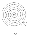
- the vertices S are on an Archimedean spiral, cf. Fig. 1.
- the center (0, 0) of the coordinate system is the starting point inside the spiral.
- the arc length L between two adjacent points S 1 and S 2 is then at a distance of the spiral turns.
- the individual points S 1 , S 2 ... are obtained by continued removal of the constant arc length L along the spiral from inside to outside.
- the vertices may be arranged equidistant from each other.
- a variable arc length L possible. So can one from the inside out increasing arc length L can be selected.
- the facets become larger, the Height of the elevations or the depth of the wells is larger and the scattering effect is also greater.
- the light field then has a rather small half - beam angle with quite high illuminance in the Center on. In contrast, at constant L, the Illuminance rather plateau-shaped and soft leaking.
- the aforementioned measures allow, in a variety of ways, the diffuser to the respective lighting system, for example the respective reflector to adapt.
- the diffuser to the respective lighting system for example the respective reflector to adapt.
- the value of the arc length L but also by variation or constancy of the arc length an adaptation to a reflector respectively.
- These measures allow the light field in to influence given areas of the lighting system, to strengthen or weaken it locally, thus allowing for varied way to optimize the light field.
- a lens which has a transparent base body with a first surface, wherein the first surface is divided into facets, and in which each facet is associated with a protrusion or depression with a second, curved surface formed, and in the the vertices of the elevations and / or depressions are characterized in that their coordinates (x s , y s ) from the coordinates ( x P , y P ) of all points P, which form an array of facets with regular hexagonal edge contour, by rotation by an angle ⁇ around a center (0,0).
- the first equation stands for a set of horizontally aligned lines.
- the second equation describes a set of positive slope straight lines of tan 60 °, and the third equation describes a set of negative slope tan lines of 120 °.
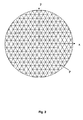
- intersections P which are shown in FIG.
- the intersections lying in a plane have the coordinates ( x P , y P ) with x as horizontal and y as vertical axis.
- x P , y P the coordinates
- x the coordinates
- y P the coordinates
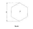
- Fig. 3a shows such a facet with diagonal D in a plan view.
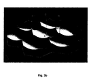
- Fig. 3b shows this according to a section of a Diffuser with curved recesses with apex S. Zu Each recess has a hexagonal edge contour.
- Equation system 2 where N, X ', Y', R 'and ⁇ ' represent mathematical intermediate variables.
- the output coordinates ( x P , y P ) are thus transformed to final coordinates ( x P ', y P ').
- each point P undergoes a shift by a certain arc length L. With the distance of the points P from the center (0,0) this takes Arc length too. It may increase linearly as seen in Figure 4, or the increase may be with a root or exponential function.
- the set of all points ( x P ', y P ') is in the sense of the above statements in a plane. This requires a flat body. If desired, however, a curved body can be provided. In this case, the set of all points ( x P ', y P ') must still be mapped onto the curved surface in an appropriate way.
- S and P are different with respect to the z-coordinates, with the z-axis being perpendicular to the drawing plane of FIG.
- the difference in the z-coordinate represents the height of the elevation or the depth of the recess.
- , can be chosen variably.
- the angle ⁇ for the Transformation is not constant but increases with increasing Distance from the center to. In this respect, too large ⁇ am Diffuser edge can be avoided as desired, and this at sufficient scattering effect inside the lens.
- a lens which has a transparent base body with a first surface, wherein the first surface is subdivided into facets, and wherein each facet is associated with a protrusion or depression with a second, curved surface formed, and in the the vertices S of the elevations or depressions are characterized in that their coordinates ( x S ", y S "), the coordinates ( x P , y P ) of all points P, which form an array of facets with regular hexagonal edge contour, by random variation using the Monte Carlo method.
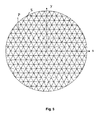
- FIG. 5 shows, on the one hand, the points of intersection P of an arrangement of facets with a regular hexagonal edge contour according to system of equations 1 with the coordinates ( x P , y P ) as in FIG. 2, supplemented by the points S obtained via the Monte Carlo method Coordinates ( x S ", y S ") which represent the vertices of the elevations or depressions.
- the parameters U and V are in the range of approximately 5%. to about 20% of the facet diagonals D. Be U or V even larger chosen, so there is an increasing danger that the body has gaps between the facets.
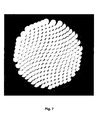
- Fig. 6 shows a facet arrangement similar to EP 0 961 136 A1.
- the diffuser has a diameter of 138 mm and is covered with facets with a regular hexagonal edge contour. Each hexagon has a diagonal D of 10 mm.
- Each bump is spherically curved with a radius of curvature of 10 mm.
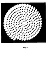
- Fig. 9 shows a lens with a diameter of 138 mm, in which the Vertices are arranged on an Archimedean spiral.
- the Output facet was regularly contoured hexagonal as in Fig. 6, however with a diagonal D of 12 mm.
- the spiral spacing d is 9 mm, and the arc length L is also 9 mm.
- Any spherical arched Elevation has a radius of curvature of 10 mm.
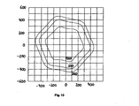
- the isolux distribution shows values of constant illuminance of 1000, 500 and 200 lux.
- the values of constant illuminance take a hexagonal Shape, i. the light field is overall pronounced hexagonal.
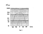
- Fig. 11 shows a so-called horizontal for the same lamp Illuminance distribution, ie the course of the illuminance along the horizontally oriented x-axis as in EP 0 961 136 A2.
- the illuminance has a central plateau-shaped Area on, and a sharp-edged garbage towards the edge.
- Fig. 12 shows the light field of the same lamp as in Fig. 10, however with a diffuser according to the invention.
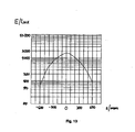
- FIG. 13 shows in a representation corresponding to FIG. 11 Result, when the lamp with a lens according to the invention Is provided.
- the course of the illuminance is bell-shaped, the slope change is slow, the light field is soft discontinued.
Landscapes
- Physics & Mathematics (AREA)
- General Physics & Mathematics (AREA)
- Optics & Photonics (AREA)
- Engineering & Computer Science (AREA)
- General Engineering & Computer Science (AREA)
- Optical Elements Other Than Lenses (AREA)
- Moulds For Moulding Plastics Or The Like (AREA)
Applications Claiming Priority (2)
| Application Number | Priority Date | Filing Date | Title |
|---|---|---|---|
| DE10343630A DE10343630B4 (de) | 2003-09-20 | 2003-09-20 | Streuscheibe |
| DE10343630 | 2003-09-20 |
Publications (2)
| Publication Number | Publication Date |
|---|---|
| EP1517160A2 true EP1517160A2 (fr) | 2005-03-23 |
| EP1517160A3 EP1517160A3 (fr) | 2005-04-13 |
Family
ID=34177861
Family Applications (1)
| Application Number | Title | Priority Date | Filing Date |
|---|---|---|---|
| EP04018197A Withdrawn EP1517160A3 (fr) | 2003-09-20 | 2004-07-31 | Disque de diffusion |
Country Status (5)
| Country | Link |
|---|---|
| US (2) | US7443588B2 (fr) |
| EP (1) | EP1517160A3 (fr) |
| JP (1) | JP4326438B2 (fr) |
| CN (2) | CN100529803C (fr) |
| DE (1) | DE10343630B4 (fr) |
Cited By (2)
| Publication number | Priority date | Publication date | Assignee | Title |
|---|---|---|---|---|
| EP2284577A3 (fr) * | 2007-11-23 | 2011-08-24 | OSRAM Opto Semiconductors GmbH | Composant optique et dispositif d'éclairage |
| DE102019102329A1 (de) * | 2019-01-30 | 2020-07-30 | Automotive Lighting Reutlingen Gmbh | Optische Scheibe für eine Beleuchtungseinrichtung |
Families Citing this family (16)
| Publication number | Priority date | Publication date | Assignee | Title |
|---|---|---|---|---|
| DE10343630B4 (de) * | 2003-09-20 | 2007-11-15 | Schott Ag | Streuscheibe |
| US7583444B1 (en) | 2005-12-21 | 2009-09-01 | 3M Innovative Properties Company | Process for making microlens arrays and masterforms |
| JP2009537870A (ja) * | 2006-05-18 | 2009-10-29 | スリーエム イノベイティブ プロパティズ カンパニー | 抽出構造体を備えた導光体の製造方法及びその方法で製造された導光体 |
| JP4935513B2 (ja) * | 2007-06-06 | 2012-05-23 | ソニー株式会社 | 光学素子およびその製造方法、ならびに光学素子作製用複製基板およびその製造方法 |
| DE102008023551B4 (de) | 2008-05-14 | 2019-05-09 | Automotive Lighting Reutlingen Gmbh | Beleuchtungseinrichtung in Form eines Projektionsscheinwerfers für Kraftfahrzeuge |
| IL196690A0 (en) * | 2008-05-29 | 2011-08-01 | Plasan Sasa Ltd | Interchangeable door |
| DE102008060969A1 (de) * | 2008-12-08 | 2010-06-10 | Osram Gesellschaft mit beschränkter Haftung | Streuscheibe |
| JP5510865B2 (ja) * | 2009-03-25 | 2014-06-04 | 住友化学株式会社 | 防眩処理方法、防眩フィルムの製造方法および金型の製造方法 |
| US10222025B2 (en) * | 2014-01-23 | 2019-03-05 | Philips Lighting Holding B.V. | Light diffuser, LED lamp arrangement using the same, and manufacturing method |
| US20150307033A1 (en) * | 2014-04-29 | 2015-10-29 | Global Ip Holdings, Llc | Vehicle trim part having a layered, decorative finish and configured to form a light pattern at the front of the part |
| CN103926639B (zh) * | 2014-04-30 | 2016-08-31 | 张家港康得新光电材料有限公司 | 一种增亮膜及其制作方法以及包含该增亮膜的背光模组 |
| JP6390194B2 (ja) * | 2014-06-18 | 2018-09-19 | オムロン株式会社 | 光学素子及び面光源装置 |
| EP3458884B1 (fr) * | 2016-05-19 | 2020-07-15 | Signify Holding B.V. | Dispositif de sortie optique et procédé de conception |
| CN109398220A (zh) * | 2017-08-18 | 2019-03-01 | 深圳市绎立锐光科技开发有限公司 | 车前大灯调节装置及系统 |
| DE102018131556A1 (de) | 2018-12-10 | 2020-06-10 | HELLA GmbH & Co. KGaA | Verfahren zur Herstellung eines optischen Bauteils, optisches Bauteil sowie Beleuchtungsvorrichtung für ein Kraftfahrzeug |
| CN113251382A (zh) * | 2021-05-11 | 2021-08-13 | 深圳市照耀科技有限公司 | 一种珠面及使用该珠面的透镜 |
Citations (3)
| Publication number | Priority date | Publication date | Assignee | Title |
|---|---|---|---|---|
| US4823246A (en) * | 1986-12-23 | 1989-04-18 | Cibie Projecteurs | Shallow indicator light for a motor vehicle |
| EP0961136A2 (fr) | 1998-05-28 | 1999-12-01 | CLAY PAKY S.p.A. | Diffuseur optique et dispositif d' éclairage ainsi équipé |
| US6086227A (en) * | 1998-09-11 | 2000-07-11 | Osram Sylvania Inc. | Lamp with faceted reflector and spiral lens |
Family Cites Families (20)
| Publication number | Priority date | Publication date | Assignee | Title |
|---|---|---|---|---|
| JPS57139927U (fr) * | 1981-02-27 | 1982-09-01 | ||
| JPS61142648A (ja) | 1984-12-14 | 1986-06-30 | Hitachi Ltd | 走査電子顕微鏡用試料台 |
| JP2566417B2 (ja) * | 1987-08-05 | 1996-12-25 | 旭光学工業株式会社 | 焦点板 |
| US5042911A (en) * | 1989-03-08 | 1991-08-27 | Gte Products Corporation | Method of making lighting lens |
| US5124839A (en) * | 1989-11-08 | 1992-06-23 | Canon Kabushiki Kaisha | Phase-type focusing screen |
| US5119235A (en) * | 1989-12-21 | 1992-06-02 | Nikon Corporation | Focusing screen and method of manufacturing same |
| US5177637A (en) * | 1990-09-11 | 1993-01-05 | Nikon Corporation | Focusing screen including different height microlenses arranged in a cyclical pattern |
| US5247390A (en) * | 1991-11-05 | 1993-09-21 | Aharon Zeev Hed | Lightweight low-loss refractive light diffusion system |
| US5965327A (en) * | 1991-12-03 | 1999-10-12 | Asahi Kogaku Kogyo Kaisha | Method for manufacturing a master die for a diffusion plate and diffusion manufactured by said method |
| JPH06102415A (ja) * | 1992-09-24 | 1994-04-15 | Keiwa Shoko Kk | 集光板 |
| CA2108959A1 (fr) * | 1992-11-16 | 1994-05-17 | Thomas M. Golz | Lentille lenticulaire |
| US5442252A (en) * | 1992-11-16 | 1995-08-15 | General Electric Company | Lenticulated lens with improved light distribution |
| US5995303A (en) * | 1994-09-30 | 1999-11-30 | Kabushiki Kaisha Toshiba | Optical element and optical device |
| US5580164A (en) * | 1995-03-07 | 1996-12-03 | High End Systems, Inc. | Power lens for an automated luminaire |
| US6079854A (en) * | 1998-02-13 | 2000-06-27 | Ra; Dojin | Device and method for diffusing light |
| US6822794B2 (en) * | 2000-12-15 | 2004-11-23 | Agilent Technologies, Inc. | Diffractive optical element for providing favorable multi-mode fiber launch and reflection management |
| CN2462424Y (zh) * | 2001-01-12 | 2001-11-28 | 唐世杰 | 扩散聚光片 |
| US6778148B1 (en) * | 2002-12-04 | 2004-08-17 | The United States Of America As Represented By The Secretary Of The Navy | Sensor array for enhanced directivity |
| DE10343630B4 (de) * | 2003-09-20 | 2007-11-15 | Schott Ag | Streuscheibe |
| DE10361121A1 (de) * | 2003-12-22 | 2005-07-21 | Schott Ag | Optische Anordnung mit Stufenlinse |
-
2003
- 2003-09-20 DE DE10343630A patent/DE10343630B4/de not_active Expired - Fee Related
-
2004
- 2004-07-31 EP EP04018197A patent/EP1517160A3/fr not_active Withdrawn
- 2004-09-13 JP JP2004265175A patent/JP4326438B2/ja not_active Expired - Fee Related
- 2004-09-16 US US10/943,120 patent/US7443588B2/en not_active Expired - Fee Related
- 2004-09-20 CN CNB2004100798111A patent/CN100529803C/zh not_active Expired - Fee Related
- 2004-09-20 CN CN2009101594434A patent/CN101725893B/zh not_active Expired - Fee Related
-
2008
- 2008-09-19 US US12/233,851 patent/US7729054B2/en not_active Expired - Fee Related
Patent Citations (3)
| Publication number | Priority date | Publication date | Assignee | Title |
|---|---|---|---|---|
| US4823246A (en) * | 1986-12-23 | 1989-04-18 | Cibie Projecteurs | Shallow indicator light for a motor vehicle |
| EP0961136A2 (fr) | 1998-05-28 | 1999-12-01 | CLAY PAKY S.p.A. | Diffuseur optique et dispositif d' éclairage ainsi équipé |
| US6086227A (en) * | 1998-09-11 | 2000-07-11 | Osram Sylvania Inc. | Lamp with faceted reflector and spiral lens |
Cited By (3)
| Publication number | Priority date | Publication date | Assignee | Title |
|---|---|---|---|---|
| EP2284577A3 (fr) * | 2007-11-23 | 2011-08-24 | OSRAM Opto Semiconductors GmbH | Composant optique et dispositif d'éclairage |
| US8757849B2 (en) | 2007-11-23 | 2014-06-24 | Osram Gesellschaft Mit Beschrankter Haftung | Optical component and illumination device |
| DE102019102329A1 (de) * | 2019-01-30 | 2020-07-30 | Automotive Lighting Reutlingen Gmbh | Optische Scheibe für eine Beleuchtungseinrichtung |
Also Published As
| Publication number | Publication date |
|---|---|
| JP4326438B2 (ja) | 2009-09-09 |
| US7443588B2 (en) | 2008-10-28 |
| CN100529803C (zh) | 2009-08-19 |
| CN1598398A (zh) | 2005-03-23 |
| CN101725893A (zh) | 2010-06-09 |
| CN101725893B (zh) | 2013-10-23 |
| HK1073684A1 (zh) | 2005-10-14 |
| JP2005092205A (ja) | 2005-04-07 |
| US20090015925A1 (en) | 2009-01-15 |
| EP1517160A3 (fr) | 2005-04-13 |
| US7729054B2 (en) | 2010-06-01 |
| HK1144164A1 (en) | 2011-01-28 |
| DE10343630B4 (de) | 2007-11-15 |
| DE10343630A1 (de) | 2005-05-25 |
| US20050063064A1 (en) | 2005-03-24 |
Similar Documents
| Publication | Publication Date | Title |
|---|---|---|
| EP1517160A2 (fr) | Disque de diffusion | |
| DE60212598T2 (de) | Prismatischer retroreflektor mit einer multiplanaren facette | |
| DE10254499B4 (de) | Schichtanordnung mit einer einen linsenartigen Effekt erzeugenden beugungsoptisch wirksamen Struktur | |
| DE1497626B1 (de) | Corneakontaktlinsenprobesatz und Corneakontaktlinsen | |
| DE202009018881U1 (de) | Aphakische Intraokularlinse | |
| EP2102545B1 (fr) | Plaque transparente comprenant une structure superficielle pour déclencher de manière essentiellement non éblouissante la lumière produite par une lampe | |
| DE4242264C2 (de) | Körper oder Bauteil mit einer Mikrodoppeltripel aufweisenden Oberfläche sowie Verfahren zur Herstellung eines derartigen Körpers oder Bauteils | |
| EP2436281A1 (fr) | Pierre décorative dotée d'une taille brillante | |
| DE4241889C2 (de) | Leuchtenabdeckung mit optischer Wirkung für eine Fahrzeugbeleuchtungseinrichtung | |
| EP3891552B1 (fr) | Verre de lunettes, famille de verres de lunettes, procédé de conception d'une famille de verres de lunettes et procédé de fabrication d'un verre de lunettes | |
| EP2561408A1 (fr) | Objet fabriqué selon un procédé de moulage et marqué avec une grille de diffraction, et son procédé de fabrication | |
| EP2356498A1 (fr) | Verre diffuseur | |
| DE69927082T2 (de) | Fahrzeuglampe | |
| EP3995868B1 (fr) | Rétroréflecteur à parquetage apériodique | |
| AT515136A1 (de) | Schmuckstein mit sternförmigem Erscheinungsbild | |
| EP1685348B1 (fr) | Lampe a element de sortie de lumiere transparent | |
| WO2022233450A1 (fr) | Élément de sécurité optiquement variable | |
| EP4034805A1 (fr) | Élément optique | |
| WO2014072165A1 (fr) | Pièce façonnée en matière plastique | |
| EP3256775B1 (fr) | Procédé de fabrication d'un outil de moulage par injection et procédé de fabrication d'un élément optique | |
| DE102018132620A1 (de) | Verfahren zum Herstellen eines Negativs einer optischen Fläche eines optischen Elements einer Kraftfahrzeugbeleuchtungsvorrichtung | |
| DE10018831B4 (de) | Reflektoranordnung | |
| DE102022132407A1 (de) | Spiegelelement und entsprechendes Herstellungsverfahren | |
| DE1101318B (de) | Lichtdurchlaessige, lichtbrechende Platte | |
| DE20320375U1 (de) | Reflektor mit strukturierter Oberfläche, sowie Leuchte und Sekundärbeleuchtungssystem mit einem solchen Reflektor |
Legal Events
| Date | Code | Title | Description |
|---|---|---|---|
| PUAI | Public reference made under article 153(3) epc to a published international application that has entered the european phase |
Free format text: ORIGINAL CODE: 0009012 |
|
| PUAL | Search report despatched |
Free format text: ORIGINAL CODE: 0009013 |
|
| 17P | Request for examination filed |
Effective date: 20040731 |
|
| AK | Designated contracting states |
Kind code of ref document: A2 Designated state(s): AT BE BG CH CY CZ DE DK EE ES FI FR GB GR HU IE IT LI LU MC NL PL PT RO SE SI SK TR |
|
| AX | Request for extension of the european patent |
Extension state: AL HR LT LV MK |
|
| AK | Designated contracting states |
Kind code of ref document: A3 Designated state(s): AT BE BG CH CY CZ DE DK EE ES FI FR GB GR HU IE IT LI LU MC NL PL PT RO SE SI SK TR |
|
| AX | Request for extension of the european patent |
Extension state: AL HR LT LV MK |
|
| AKX | Designation fees paid |
Designated state(s): DE FR GB IT |
|
| 17Q | First examination report despatched |
Effective date: 20051114 |
|
| RAP1 | Party data changed (applicant data changed or rights of an application transferred) |
Owner name: AUER LIGHTING GMBH |
|
| STAA | Information on the status of an ep patent application or granted ep patent |
Free format text: STATUS: THE APPLICATION HAS BEEN WITHDRAWN |
|
| 18W | Application withdrawn |
Effective date: 20110217 |