EP1517760B1 - Stempel mit Halterungssystem für eine Abstreiferplatte - Google Patents
Stempel mit Halterungssystem für eine Abstreiferplatte Download PDFInfo
- Publication number
- EP1517760B1 EP1517760B1 EP03734463A EP03734463A EP1517760B1 EP 1517760 B1 EP1517760 B1 EP 1517760B1 EP 03734463 A EP03734463 A EP 03734463A EP 03734463 A EP03734463 A EP 03734463A EP 1517760 B1 EP1517760 B1 EP 1517760B1
- Authority
- EP
- European Patent Office
- Prior art keywords
- stripper plate
- guide
- punch
- assembly
- plate guide
- Prior art date
- Legal status (The legal status is an assumption and is not a legal conclusion. Google has not performed a legal analysis and makes no representation as to the accuracy of the status listed.)
- Expired - Lifetime
Links
- 230000014759 maintenance of location Effects 0.000 title description 7
- 230000007246 mechanism Effects 0.000 claims description 25
- 230000000994 depressogenic effect Effects 0.000 claims description 7
- 230000002093 peripheral effect Effects 0.000 claims description 6
- 230000001627 detrimental effect Effects 0.000 claims description 3
- 239000002245 particle Substances 0.000 claims description 3
- 238000004080 punching Methods 0.000 description 3
- 230000000712 assembly Effects 0.000 description 2
- 238000000429 assembly Methods 0.000 description 2
- 238000004519 manufacturing process Methods 0.000 description 2
- 238000000034 method Methods 0.000 description 2
- 238000006049 ring expansion reaction Methods 0.000 description 2
- 241001364096 Pachycephalidae Species 0.000 description 1
- 239000011248 coating agent Substances 0.000 description 1
- 238000000576 coating method Methods 0.000 description 1
- 230000006835 compression Effects 0.000 description 1
- 238000007906 compression Methods 0.000 description 1
- 230000000881 depressing effect Effects 0.000 description 1
- 230000000694 effects Effects 0.000 description 1
- 239000012530 fluid Substances 0.000 description 1
- 238000009434 installation Methods 0.000 description 1
- 239000000314 lubricant Substances 0.000 description 1
- 230000001050 lubricating effect Effects 0.000 description 1
- 230000013011 mating Effects 0.000 description 1
- 239000002184 metal Substances 0.000 description 1
- 230000000452 restraining effect Effects 0.000 description 1
- 239000007787 solid Substances 0.000 description 1
Images




Classifications
-
- B—PERFORMING OPERATIONS; TRANSPORTING
- B21—MECHANICAL METAL-WORKING WITHOUT ESSENTIALLY REMOVING MATERIAL; PUNCHING METAL
- B21D—WORKING OR PROCESSING OF SHEET METAL OR METAL TUBES, RODS OR PROFILES WITHOUT ESSENTIALLY REMOVING MATERIAL; PUNCHING METAL
- B21D45/00—Ejecting or stripping-off devices arranged in machines or tools dealt with in this subclass
- B21D45/003—Ejecting or stripping-off devices arranged in machines or tools dealt with in this subclass in punching machines or punching tools
- B21D45/006—Stripping-off devices
-
- Y—GENERAL TAGGING OF NEW TECHNOLOGICAL DEVELOPMENTS; GENERAL TAGGING OF CROSS-SECTIONAL TECHNOLOGIES SPANNING OVER SEVERAL SECTIONS OF THE IPC; TECHNICAL SUBJECTS COVERED BY FORMER USPC CROSS-REFERENCE ART COLLECTIONS [XRACs] AND DIGESTS
- Y10—TECHNICAL SUBJECTS COVERED BY FORMER USPC
- Y10T—TECHNICAL SUBJECTS COVERED BY FORMER US CLASSIFICATION
- Y10T83/00—Cutting
- Y10T83/202—With product handling means
- Y10T83/2092—Means to move, guide, or permit free fall or flight of product
- Y10T83/2096—Means to move product out of contact with tool
- Y10T83/2135—Moving stripper timed with tool stroke
- Y10T83/215—Carried by moving tool element or its support
- Y10T83/2155—Stripper biased against product
- Y10T83/2159—By spring means
-
- Y—GENERAL TAGGING OF NEW TECHNOLOGICAL DEVELOPMENTS; GENERAL TAGGING OF CROSS-SECTIONAL TECHNOLOGIES SPANNING OVER SEVERAL SECTIONS OF THE IPC; TECHNICAL SUBJECTS COVERED BY FORMER USPC CROSS-REFERENCE ART COLLECTIONS [XRACs] AND DIGESTS
- Y10—TECHNICAL SUBJECTS COVERED BY FORMER USPC
- Y10T—TECHNICAL SUBJECTS COVERED BY FORMER US CLASSIFICATION
- Y10T83/00—Cutting
- Y10T83/929—Tool or tool with support
- Y10T83/9295—Work supported tool [e.g., clicker die]
- Y10T83/9307—With tool contour adjusting means
-
- Y—GENERAL TAGGING OF NEW TECHNOLOGICAL DEVELOPMENTS; GENERAL TAGGING OF CROSS-SECTIONAL TECHNOLOGIES SPANNING OVER SEVERAL SECTIONS OF THE IPC; TECHNICAL SUBJECTS COVERED BY FORMER USPC CROSS-REFERENCE ART COLLECTIONS [XRACs] AND DIGESTS
- Y10—TECHNICAL SUBJECTS COVERED BY FORMER USPC
- Y10T—TECHNICAL SUBJECTS COVERED BY FORMER US CLASSIFICATION
- Y10T83/00—Cutting
- Y10T83/929—Tool or tool with support
- Y10T83/9411—Cutting couple type
- Y10T83/9423—Punching tool
-
- Y—GENERAL TAGGING OF NEW TECHNOLOGICAL DEVELOPMENTS; GENERAL TAGGING OF CROSS-SECTIONAL TECHNOLOGIES SPANNING OVER SEVERAL SECTIONS OF THE IPC; TECHNICAL SUBJECTS COVERED BY FORMER USPC CROSS-REFERENCE ART COLLECTIONS [XRACs] AND DIGESTS
- Y10—TECHNICAL SUBJECTS COVERED BY FORMER USPC
- Y10T—TECHNICAL SUBJECTS COVERED BY FORMER US CLASSIFICATION
- Y10T83/00—Cutting
- Y10T83/929—Tool or tool with support
- Y10T83/9457—Joint or connection
- Y10T83/9464—For rotary tool
-
- Y—GENERAL TAGGING OF NEW TECHNOLOGICAL DEVELOPMENTS; GENERAL TAGGING OF CROSS-SECTIONAL TECHNOLOGIES SPANNING OVER SEVERAL SECTIONS OF THE IPC; TECHNICAL SUBJECTS COVERED BY FORMER USPC CROSS-REFERENCE ART COLLECTIONS [XRACs] AND DIGESTS
- Y10—TECHNICAL SUBJECTS COVERED BY FORMER USPC
- Y10T—TECHNICAL SUBJECTS COVERED BY FORMER US CLASSIFICATION
- Y10T83/00—Cutting
- Y10T83/929—Tool or tool with support
- Y10T83/9457—Joint or connection
- Y10T83/9473—For rectilinearly reciprocating tool
- Y10T83/9476—Tool is single element with continuous cutting edge [e.g., punch, etc.]
Definitions
- the present invention relates generally to punch guides, such as those used with industrial punch presses. More particularly, this invention relates to punch guides with stripper plate retention assemblies according to the preamble of claim 1. Such a punch guide assembly is known from EP 770 437 .
- Each punch station operates as a punch set holder for a removable punch set that includes a centrally-disposed punch surrounded by a punch guide and biased by a punch spring.
- the operator may wish to change some or all of the punch set and die combinations from time to time. For instance, the operator may wish to utilize a different punch tip shape or size in a punch set. It is desirable to minimize the time required, and make it simple, to change the punch and die components, so that down time on the punch machine is minimized.
- the punch guide is oriented with the stripper plate flush against the workpiece surface.
- Another configuration uses a flattened metal clip or the like to retain a removable stripper plate at the end of a punch guide. This allows the use of a number of different punches with each guide, since only the stripper plate needs to be changed to accommodate a new punch.
- These spring clip structures have not provided completely satisfactory performance. Often, the workpiece surface will have a thin coating of oil or other fluid. When the stripper plate meets the workpiece surface, a suction may be created. When this occurs, the stripper plate may be pulled out of place and damage may result to the workpiece and to the stripper plate. Down time may also be a problem. Finally, these clips tend to weaken with continued use, potentially aggravating the noted problems.
- a further configuration is shown in commonly assigned U.S. Patent 4,446,767 , wherein a locking ring 13 is fitted in matching circumferential grooves in a stripper plate 22 in the punch guide sleeve 11.
- the free ends 31 of the locking ring 13 include tabs 32 that can be spread apart and locked into position by the locking ring expansion lock 14.
- installation and removal of the stripper plate is relatively simple, it involves handling the loose ring 13 and the cap screw used as the locking ring expansion lock 14. In some cases, the manipulation of these small parts may be more difficult and time consuming than is preferred.
- an O-ring 25 in annular mating grooves in the punch guide sleeve and the stripper plate provides a snap fit of the stripper plate 21 to the punch guide 18.
- the '824 patent also illustrates a snap ring 38 for retaining the stripper plate 36 in position. Such snap rings may neither be strong enough nor reliable enough to securely lock the stripper plate in position.
- the '339 patent employs retainers 60 and spring-mounted elements 56 for engagement against V-shaped annular detent grooves 57 in the edge of the stripper plate 62. Attachment and removal involves loosening the retainers 60 and moving them aside to snap-in or unsnap the spring-loaded catches 56 in or out of the grooves. The redundant attachment mechanism requires additional steps in releasing or locking the stripper plate.
- the 718 patent shows the use of spring clips 194 attached to the punch guide and engaging internally-threaded flanges 196 in the stripper plate 46 in a fashion similar to the '111 patent.
- Such spring clips may not be strong enough for large diameter punch sets and may weaken with repeated use.
- the '484 patent discloses a complex locking ring 80 with positioning springs 90, 92 located within a groove and positioned between a pair of diametrically-opposed pins 94, 96 that engage other pins, such as 98, to hold the ring 80 in the lock position.
- the stripper plate 74 is held in place in the locking ring by centrally-extending flanges 109 and pin-receiving slots 110.
- the locking ring 80 is turned about the axis of the punch assembly against the compression of the springs 90, 92, thereby aligning the pin-receiving slots 110 with the pin 74D and allowing the stripper plate 74 to be removed and re-inserted in the fashion of a bayonet-lock mechanism. Then, by pushing the stripper plate in and depressing the release pin 112, the springs 90, 92 rotate the locking ring 80 on the box 76 so the flanges 109 cover the pins 74D, thereby holding the stripper plate 74 securely in place on the end of the punch assembly 10.
- This rotatable retaining ring and stripper plate assembly includes a number of small parts, such as pins and springs, that add complexity and fabrication costs. Moreover, the stripper plate retaining ring itself is removed when the stripper plate is released, thus potentially risking its loss or damage if dropped.
- U.S. Patent 6,047,621 discloses another mechanism for removing and replacing a stripper plate from a punch guide.
- This mechanism includes slides 80 mounted on a punch guide for axial movement along the front end of the guide.
- the slides 80 are forwardly and rearwardly movable between locked and unlocked positions.
- Each slide 80 is locked in position by a spring-loaded button assembly 82 extending radially from the guide 14 through an opening 84 in the lower portion of the slide 80.
- the button 82 is pressed inward, thereby releasing the slide 80.
- the slide is then urged forward, which causes a ball bearing 86 positioned between an upper, recessed inner surface 88 of the slide 80 and a groove 90 in the periphery of the stripper plate 20 to move radially outward.
- This causes the ball bearing 86 to move out of engagement with the groove 90 in the outer edge of the stripper plate.
- one must depress the button on each of the slides 80 and then push each of the slides 80 to the front of the guide. This is less than ideal in terms of ease of stripper plate removal and replacement.
- U.S. Patent 6,082,516 discloses a stripper plate release mechanism comprising a locking ring with three arcuate grooves having radially-increasing dimension and three locking clips which are circumferentially fixed relative to the locking ring.
- the locking clips engage the stripper plate.
- the locking clips ride in the arcuate grooves which act as camming surfaces and open the locking clips, thereby releasing the stripper plate.
- this mechanism requires a rotation step to release the stripper plate. It would be desirable to provide a stripper plate release mechanism that does not require rotation or substantial manipulation to remove and replace the stripper plate.
- EP-A-0770437 discloses a punch guide assembly in accordance with the precharacterising part of claim 1. In order to remove the stripping plate a two-step-release-process is required.
- FIG. 1 illustrates a punch assembly 10 comprising a stripper plate retention system in accordance with one embodiment of the present invention.
- the illustrated punch assembly 10 generally includes a punch 50, a punch guide 16, a stripper plate 22, a stripper plate guide 44, a punch holder 54, and a punch driver 62.
- the punch 50 is centrally disposed and has a punch tip 52 adapted to extend through an opening 13 in the stripper plate 22.
- the illustrated punch assembly 10 includes a punch spring 64 surrounding the punch driver 62.
- the punch spring 64 is held in position by collar 66 and block 68.
- Collar 66 is secured to the punch guide 16 by fasteners 77, and block 68 is secured to the punch driver 62 by fasteners 88.
- the collar 66 when assembled, also bears against the flange 70 of the punch driver 62 to maintain the noted components in the assembled state depicted in Figure 1 .
- stripper plate retention system is not limited to use with the punch assembly 10 shown in Figure 1 . Rather, the stripper plate retention system can be used with a wide variety of different types of punch assemblies, as will be apparent to skilled artisans.
- the punch guide 16 is inserted into, for example, a holder in the turret of a punch press (not shown), and the ram of the punch press strikes the punch driver 62 to force the punch tip 52 through a workpiece (not shown) into the opening of a matching die (not shown).
- the punch spring 64 is thus compressed during the punching operation and operates to withdraw the punch tip 52 from the die and workpiece upon retraction of the ram.
- the stripper plate 22 operates in a well known manner to strip away the punched-out blank and other debris that becomes attached to the punch tip 52.
- the punch guide 16 is part of a punch guide assembly for removably carrying the stripper plate 22.
- the punch guide assembly also comprises a stripper plate guide 44 that is movable axially (i.e., along the axis A of the punch guide 16) with respect to the punch guide 16.
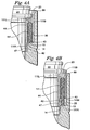
- the stripper plate guide 44 has a locked position (depicted in Figures 1 , 3A-3B , 4A , and 5A ), wherein the stripper plate 22 is secured to the punch guide assembly, and an unlocked position (depicted in Figures 2 , 3C-3D , 4B , and 5B ), wherein the stripper plate 22 can be readily removed from the punch guide assembly.
- the punch guide assembly is adapted to removably retain the stripper plate 22.
- the stripper plate guide 44 is resiliently biased axially toward its unlocked position. Thus, the stripper plate guide 44 is moved to its unlocked position when the stripper plate guide 44 is not restrained (as described below) against axial movement relative to the punch guide 16.
- the stripper plate guide 44 is resiliently biased by at least one spring 111 bearing against the stripper plate guide 44.
- the assembly may comprise a plurality of springs 111 extending between the stripper plate guide 44 and the punch guide 16. A variety of mechanisms can be used to bias the stripper plate guide toward its unlocked position.
- the stripper plate guide 44 is carried against an interior wall of the punch guide 16. This can be understood with reference to Figures 1 and 2 , wherein the stripper plate guide 44 is mounted against the interior of the leading wall section 11 of the punch guide 16. As can be appreciated, this wall section 11 is at the leading (i.e., nearest the workpiece during use) end region of the punch guide 16. In the illustrated embodiment, the leading wall section 11 has an interiorly-facing (i.e., facing radially inward) surface 26 against which an exteriorly-facing (i.e., facing radially outward) surface 46 of the stripper plate guide 44 slides when the stripper plate guide 44 is moved axially with respect to the punch guide 16.
- the illustrated punch guide 16 has a base wall section 18 extending between the leading wall section 11 and the base flange 19 of the punch guide 16.
- the leading wall section 11 preferably has a greater interior dimension (e.g., diameter) than the base wall section 18.
- these wall sections 11, 18 have the same exterior dimensions (e.g., the same exterior diameter), such that the base wall section 18 has a greater wall thickness than the leading wall section 11.
- the base wall section 18 preferably has a first shoulder 14 defined by a first forward-facing (i.e., facing the workpiece during use) surface 13 and a first interiorly-facing surface 12.
- the stripper plate guide 44 has a rear surface 43 which, when the stripper plate guide 44 is in its locked position, bears against the forward-facing surface 13 of the punch guide's first shoulder 14.
- the base wall section 18 has a second shoulder 17 defined by a second forward-facing surface 15 and a second interiorly-facing surface 25.
- This optional second shoulder 17 is advantageous in that it can be configured to cooperate with a flange 47 on the stripper plate guide 44 to substantially conceal the springs 111 against exposure to dirt and other particles that can be detrimental to proper functioning of the springs 111. Particularly preferred embodiments of this nature are described below in further detail.
- the stripper plate guide 44 preferably comprises a generally ring-shaped wall. This is best appreciated with reference to Figure 9 , wherein there is illustrated an exploded perspective view a punch guide 16, a stripper plate guide 44, and a stripper plate 22 in accordance with certain embodiments of the invention.
- the punch guide 16 comprises a generally-cylindrical wall against the interior of which (i.e., against the interior of the leading wall section 11 of which) the stripper plate guide 44 is carried.
- the stripper plate guide 44 in these embodiments preferably has an exterior diameter that is slightly less than the interior diameter of the punch guide wall against which the stripper plate guide 44 is carried.
- the exterior diameter of the exteriorly-facing surface 46 of the stripper plate guide 44 is preferably slightly less than the interior diameter of the interiorly-facing surface 26 of the punch guide 16.
- certain preferred embodiments provide a stripper plate guide 44 that is resiliently biased axially toward its unlocked position by at least one spring 111.
- a spring 111 mounted in a bore 111 B formed in the stripper plate guide 44.
- the length of the bore 111B is greater than the spring's solid length (i.e., the length of the spring 111 under sufficient load to bring all coils into contact with adjacent coils).
- the spring 111 when at its free length (i.e., the overall length of the spring 111 in its unloaded position), is preferably sized to extend somewhat out of the bore 111B.
- Figure 4A depicts the spring 111 in a compressed state, which occurs when the stripper plate guide 44 is in its locked position.
- the leading end 111L of the spring 111 applies a forward force to the stripper plate guide 44
- the rear end 111 R of the spring 111 applies a rearward force to the forward-facing surface 13 of the punch guide's first shoulder 14.
- the stripper plate guide 44 is urged by the spring 111 toward its unlocked position.
- the assembly includes at least one spring mounted in a bore formed in the punch guide 16.
- the illustrated spring 111' is mounted in a bore 111B' formed in the base wall section 18' of the punch guide 16'.
- the illustrated spring 111' opens through a forward-facing surface 13' of the punch guide's shoulder 14'.
- the spring 111' is preferably sized to extend somewhat out of the bore 111B' when the spring 111' is at its free length.
- its leading end 111 L' applies forward force to the rear surface 43' of the stripper plate guide 44'
- its rear end 111 R' applies rearward force to the base wall section 18' of the punch guide 16'.
- certain alternate embodiments provide an assembly comprising at least one spring having its leading end (and its leading length) housed in a bore formed in the stripper plate guide 44 and having its rear end (and its rear length) housed in a bore formed in the punch guide 16.
- the spring in such embodiments preferably has a free length that is somewhat greater than the combined length of both bores. Thus, when the spring is compressed, its leading end applies forward force to the stripper plate guide 44, and its rear end applies rearward force to the punch guide 16.
- Skilled artisans will recognize that a variety of other mechanisms can be used to bias the stripper plate guide and such mechanisms fall within the scope of the invention.
- the stripper plate guide 44 is resiliently biased toward its unlocked position by a plurality of springs 111.
- Figures 1 and 2 depict an embodiment wherein a plurality of springs 111 extend between the punch guide 16 and the stripper plate guide 44.
- the springs 111 are mounted in bores that are spaced about the circumference of the stripper plate guide 44. This can be appreciated by referring to Figure 9 .
- any number of springs 111 can be provided in the present embodiments. In one embodiment, five springs 111 are spaced every 72 degrees or so around the circumference of the stripper plate guide 44. In another embodiment, six springs are spaced every 60 degrees or so around the circumference of the stripper plate guide 44. Many other embodiments of this nature will be obvious to skilled artisans.
- the invention provides a number of particularly preferred embodiments wherein the springs 111 are disposed within a substantially-concealed enclosure 111 H whether the stripper plate guide 44 is in its locked position or its unlocked position.
- the springs 111 in these embodiments are maintained in this enclosure 111 H at all positions between the locked position and the unlocked position.
- the spring enclosure 111 H is preferably defined by the punch guide 16 in cooperation with the stripper plate guide 44.
- the stripper plate guide 44 has a flange 47 that overlaps a confronting interior surface 12 of the punch guide 16 by an extent that varies as the stripper plate guide 44 is moved between its locked position and its unlocked position.
- the spring enclosure 111 H is bounded collectively by the exteriorly-facing surface 42 of the stripper plate guide's flange 47, the rear surface 43 of the stripper plate guide 44, the forward-facing surface 13 of the punch guide's first shoulder 14, and a rear extent of the interior surface of the punch guide's leading wall section 11.
- the present embodiments are particularly advantageous because the springs 111 are maintained in the substantially-concealed enclosure 111H at all times during use. Thus, the springs 111 are protected against becoming contaminated with dirt and other particles that can be detrimental to proper functioning of the springs 111.
- the stripper plate guide 44 preferably is resiliently biased axially toward its unlocked position. When the stripper plate guide 44 is in its locked position, however, it preferably is restrained against axial movement relative to the punch guide 16.
- a variety of lock mechanisms can be used to restrain the stripper plate guide 44 when it is in its locked position.
- a catch extending between the stripper plate guide 44 and the punch guide 16 can be used.
- the term "catch" is used herein to refer to any structure extending from the stripper plate guide 44 that can be selectively engaged with the punch guide 16, or any structure extending from the punch guide 16 that can be selectively engaged with the stripper plate guide 44, to restrain axial movement of the stripper plate guide 44 relative to the punch guide 16.
- the lock mechanism comprises a button assembly.
- the stripper plate guide 44 carries a spring-loaded button 95.
- the illustrated button 95 is a one-piece locking button, a variety of locking buttons (e.g., two-piece locking buttons) can be used.
- the spring-loaded button 95 when the spring-loaded button 95 is in a locked position (i.e., when the spring 95S behind the button 95 is in an unloaded position), the outer portion of the button 95 extends into an opening 92 in the wall of the punch guide 44.
- Figure 10 illustrates an alternate embodiment wherein the lock mechanism comprises a ring spring 195.
- the ring spring 195 in the present embodiment is carried in a circumferentially-extending groove 44G' formed in the exterior surface 46' of the stripper plate guide 44'.
- the ring spring 195 preferably has at least one spring region 197 with a substantially smaller radius than the rest of the ring spring 195.
- the ring spring 195 shown in Figure 11 has two spring regions 197 at diametrically-opposed locations on the circumference of the ring spring 159. However, essentially any number (i.e., one or more) of spring regions can be provided.
- each spring region 197 extends radially outward beyond the interior surface 26' of the punch guide's leading wall section 11'.
- the outwardly-extending spring region 197 of the ring spring 195 extends into an opening 142 formed in the wall of the punch guide 16' and engages the edge 142E of this punch guide wall surrounding and defining the opening 142.
- each spring region 197 of the ring spring 195 is depressed. This frees the stripper plate guide 44' to move axially forward relative to the punch guide 16', and each spring 111' then urges the stripper plate guide 44' toward (and moves it into) its unlocked position.
- the punch guide assembly preferably includes at least one clip 80 that lockingly engages the stripper plate 22 when the stripper plate guide 44 is in its locked position.
- the illustrated clip is identified by the reference numeral 80.
- the illustrated clip 80 has a head 82 that is held against a peripheral edge of the stripper plate 22 when the stripper plate guide 44 is in its locked position.
- the illustrated stripper plate 22 has a peripheral base flange 23 that is trapped between the head 82 of the clip 80 and a front surface 45 of the stripper plate guide 44.
- the stripper plate 22 is fixedly secured to the punch guide assembly when the stripper plate guide 44 is in its locked position.
- the base 85 of the clip 80 is mounted between the stripper plate guide 44 and the punch guide 16. This can be accomplished in a variety of ways.
- the base 85 of the clip 80 can have a particular configuration, and the exteriorly-facing surface 46 of the stripper plate guide 44 can have therein formed a correspondingly-configured recess 44R adapted to receive the clip base 85.
- the illustrated clip 80 comprises a base 85 having two opposed extensions 87, such that the clip 80 has a generally "T"-shaped configuration (i.e., the base 85 of the clip 80 has a greater width W than the rest of the clip 80).
- the exterior wall of the illustrated stripper plate guide 44 defines a generally "T"-shaped recess 44R.
- the clip 80 is trapped in the recess 44H by the interior wall of the punch guide 16.
- the illustrated clip 80 has a T-shaped configuration
- the base of the clip 80 can be provided in a variety of different configurations (and the recess 44H in the stripper plate guide 44 can be provided in a variety of corresponding configurations).
- FIG 7 illustrates another clip 80' that can be used with the stripper plate retention system.
- the illustrated clip 80' is similar to that described above, except that the present clip 80' has a bent bottom length 88. Further, in this embodiment, the clip 80' would commonly not have a T-shaped configuration. Rather, the clip 80' may have a constant width W between its head 82' and its bent bottom length 88.
- a clip 80' of this nature can be mounted between the stripper plate guide 44 and the punch guide 16 in the manner depicted in Figure 10 .
- the exterior surface 46' of the stripper plate guide 44' can have therein formed a slot adapted to receive the bent bottom length 88' of the clip 80'.
- the head 82' of the clip 80' may have the same generally "C"-shaped configuration (e.g., the same arcuate bend) as the clip 80 described above.
- many other clip configurations can be used.
- alternate embodiments involve a clip having a plurality of pins or the like extending from the interior side 80S' of the clip. Such pins may be received in corresponding openings (not shown) in the exterior wall 46 of the stripper plate guide 44. Many other embodiments of this nature can be provided as well.
- the assembly comprises a plurality of clips 80.
- the illustrated stripper plate guide 44 has therein formed a plurality of circumferentially-spaced recesses 44H each adapted to receive the base of a clip 80 of the described nature.
- the clips 80 lockingly engage the stripper plate 22 when the stripper plate guide 44 is in its locked position.
- the clips 80 preferably have heads 82 that are held against a peripheral edge of the stripper plate 22 when the stripper plate guide 44 is in its locked position.
- the stripper plate guide 44 is adapted to carry three clips 80 spaced approximately every 60 degrees about the circumference of the stripper plate guide 44.
- any desired number of clips 80 can be used, although it is preferable to provide at least three clips 80 to achieve stable, secure stripper plate retention. It can be appreciated with reference to Figure 5A-5B in view of Figures 1 and 2 that axial forward movement of the stripper plate guide 44 to its unlocked position moves each clip 80 into a position wherein the head of the clip 80 is free to move somewhat away from (i.e., out of engagement with) the peripheral edge of the stripper plate 22, such that the stripper plate 22 can be readily removed from the punch guide assembly.
- the stripper plate guide 44 is preferably mounted to the punch guide 16 by at least one fastener 60, 60'. When mounted in the manner illustrated, the stripper plate guide 44 has a limited range of freedom to move axially relative to the punch guide 16. As illustrated in Figure 8A , the stripper plate guide 44 is mounted on the punch guide 16 by positioning the stripper plate guide 44 inside the leading wall section 11 of the punch guide 16 and inserting the fastener 60 (which in Figures 8A-8C is a ring pin) into an opening 61 in the stripper plate guide 44 (in the manner illustrated).
- This opening 61 preferably extends entirely through the stripper plate guide 44, opening at one end through the interiorly-facing surface 40 of the stripper plate guide 40, and opening at the other end into an elongated opening 166 (i.e., elongated in the direction of travel of the stripper plate guide 44, that is, elongated in the direction of axis A) that opens through the exteriorly-facing surface 46 of the stripper plate guide 44.
- the stripper plate guide 44 and the punch guide 44 are brought into a relative position wherein the opening 61 in the stripper plate guide 44 is aligned with an opening 67 in the punch guide 16.
- the fastener 60 (e.g., a ring pin) is then advanced through the opening 61 in the stripper plate guide 44 until the forward portion 65 (e.g., the reduced diameter portion of a ring pin) of the fastener 60 engages the opening 67 in the punch guide 16. If so desired, the forward portion 65 of the fastener 60 may be threaded, and the edge of the punch guide wall defining the opening 67 may be threaded as well, such that the fastener 60 is engaged threadingly with the wall of the punch guide 16.
- the stripper plate guide 44 With the manner depicted in Figure 8C , the stripper plate guide 44 is free to move axially between its locked position (shown in Figure 8C ) and its unlocked position (shown in Figure 8B ). In so moving the stripper plate guide 44, the elongated opening 166 in the stripper plate guide 44 allows the stripper plate guide 44 to pass freely over the head 63 of the fastener 60, which is fixed in a stationary position in the wall of the punch
- the stripper plate guide 44 is mounted to the punch guide 16 with at least two fasteners 60.
- two fasteners can be located at diametrically-opposed locations on the circumference of the punch guide, with each fastener fixed in a stationary position in the wall of the punch guide.
- any number of fasteners can be provided. Skilled artisans will recognize that a variety of other mechanisms can be used to mount the stripper plate guide on the punch guide.
- the stripper plate guide 44 is nested inside the leading wall section 11 of the punch guide 16 during use.
- the springs 111 are positioned in the spring bores 111 B, preferably after lubricating the springs 111 in a conventional manner. Such lubricant facilitates proper functioning of the springs 111. It also tends to keep the springs 111 in (i.e., it prevents them from falling out of) the spring bores 111 B, even when the stripper plate guide 44 is held in the position shown in Figure 9 .
- the button assembly 95 is positioned in a recess configured (i.e., sized and shaped) to receive the button assembly 95.
- the clips 80 are positioned in respective recesses 44R in the exterior wall 46 of the stripper plate guide 44.
- the button 95 is then depressed and aligned with the button hole 92 in the punch guide 16 while the stripper plate guide 44 is advanced to the interior of the punch guide. As the stripper plate guide 44 is so advanced, the openings 61 in the stripper plate guide 44 are moved into alignment with the corresponding openings 67 in the wall of the punch guide 16.
- a fastener 60 is then inserted from the interior side of each opening 61 in the stripper plate guide 44 into engagement with the corresponding opening 67 in the wall of the punch guide 16, as described above with reference to Figures 8A-8C .
- the stripper plate 22 may at this point be positioned on the forward surface 45 of the stripper plate guide 44.
- the stripper plate guide 44 is advanced until the spring-loaded button 95 reaches the button hole 92 in the wall of the punch guide 16, at which point the spring 95S behind the button 95 urges the button 95 radially outward into the button hole 92.
- the stripper plate guide 44 is in its locked position, wherein the stripper plate 22 is secured to the punch guide assembly.
- the operator has only to press the spring-loaded button 95.
- This moves the button 95 radially inward and out of engagement with the button hole 92 in the wall of the punch guide 44 (hence freeing the stripper plate guide to move axially forward relative to the punch guide ).
- This causes the force of the springs 111 on the stripper plate guide 44 to move the stripper plate guide 44 toward its unlocked position (i.e., the springs 111 push the stripper plate guide 44 axially forward).
- the optional tapered lip 99 of the punch guide 16 allows the heads 82 of the clips 80 to fall away from the stripper plate 22, as depicted in Figure 5B .
- the stripper plate guide 44 is in its unlocked position, and the stripper plate 22 can be freely removed from the punch guide assembly.
Landscapes
- Engineering & Computer Science (AREA)
- Mechanical Engineering (AREA)
- Punching Or Piercing (AREA)
- Perforating, Stamping-Out Or Severing By Means Other Than Cutting (AREA)
- Drilling And Boring (AREA)
- Gripping Jigs, Holding Jigs, And Positioning Jigs (AREA)
Claims (32)
- Stanzstempel-Führungsanordnung zum entnehmbaren Tragen einer Abstreifplatte (22), wobei die Anordnung eine Stanzstempelführung (16) und eine Abstreifplattenführung (44), die in Bezug auf die Stanzstempelführung (16) axial beweglich ist, umfasst, wobei die Abstreifplattenführung (44) eine verriegelte Position, in der die Abstreifplatte (22) an der Stanzstempel-Führungsanordnung befestigt ist, und eine entriegelte Position, in der die Abstreifplatte (22) einfach aus der Stanzstempel-Führungsanordnung entnommen werden kann, besitzt, wobei die Abstreifplattenführung (44) in ihre entriegelte Position axial elastisch vorbelastet ist, jedoch an einer axialen Bewegung relativ zu der Stanzstempelführung (16) gehindert wird, wenn sie in der verriegelten Position ist, wobei die Abstreifplattenführung (44) dann, wenn sie in ihrer verriegelten Position ist, an einer axialen Bewegung relativ zu der Stanzstempelführung (16) durch einen Verriegelungsmechanismus gehindert wird, wobei sich der Verriegelungsmechanismus entweder von der Abstreifplattenführung (44) erstreckt und mit der Stanzstempelführung (16) wahlweise in Eingriff gelangen kann, oder sich von der Stanzstempelführung (16) erstreckt und mit der Abstreifplattenführung (44) wahlweise in Eingriff gelangen kann, dadurch gekennzeichnet, dass der Verriegelungsmechanismus eine Knopfanordnung oder eine Ringfeder (195) umfasst, wobei eine Bedienungsperson zum Lösen der Abstreifplatte (22) von der Anordnung nur auf den Verriegelungsmechanismus drücken muss, um den Mechanismus radial einwärts zu bewegen, so dass sich die Abstreifplattenführung (44) relativ zu der Stanzstempelführung (16) frei axial vorwärts bewegen kann.
- Anordnung nach Anspruch 1, wobei die Anordnung ferner eine Stanzstempelfeder (64) umfasst, die einen Stanzstempeltrieb (62) umgibt, wobei die Stanzstempelfeder (64) in ihrer Position zwischen einem an der Stanzstempelführung (16) befestigten Kranz (66) und einem an dem Stanzstempeltrieb (62) befestigten Block (68) gehalten wird.
- Anordnung nach Anspruch 1, wobei die Abstreifplattenführung (44) gegen eine Innenwand (26) der Stanzstempelführung (16) gehalten wird.
- Anordnung nach Anspruch 1, wobei die Abstreifplattenführung (44) eine im Allgemeinen ringförmige Wand aufweist.
- Anordnung nach Anspruch 4, wobei die Abstreifplattenführung (44) in einer im Allgemeinen zylindrischen Wand (26) der Stanzstempelführung (16) angebracht ist.
- Anordnung nach Anspruch 5, wobei die Abstreifplattenführung (44) einen Außendurchmesser besitzt, der etwas kleiner als ein Innendurchmesser der im Allgemeinen zylindrischen Wand (26) der Stanzstempelführung (16) ist.
- Anordnung nach Anspruch 1, wobei die Abstreifplattenführung (44) durch mehrere Federn (111), die sich zwischen der Abstreifplattenführung (44) und der Stanzstempelführung (16) erstrecken, elastisch vorbelastet ist.
- Anordnung nach Anspruch 7, wobei die Federn (111) unabhängig davon, ob die Abstreifplattenführung (44) in ihrer verriegelten Position oder in ihrer entriegelten Position ist, in einer im Wesentlichen verborgenen Umschließung (111H) angeordnet sind.
- Anordnung nach Anspruch 8, wobei die Umschließung (111H) durch die Stanzstempelführung (16) in Zusammenwirkung mit der Abstreifplattenführung (44) definiert ist.
- Anordnung nach Anspruch 9, wobei die Abstreifplattenführung (44) einen Flansch (47) besitzt, der mit einer gegenüber befindlichen inneren Oberfläche (12) der Stanzstempelführung (16) in einem Ausmaß überlappt, das sich verändert, wenn die Abstreifplattenführung (44) zwischen ihrer verriegelten Position und ihrer entriegelten Position bewegt wird, wobei die Umschließung (111H) durch den Flansch (47) begrenzt ist.
- Anordnung nach Anspruch 10, wobei das Ausmaß der Überlappung am größten ist, wenn die Abstreifplattenführung (44) in ihrer verriegelten Position ist, und am kleinsten ist, wenn die Abstreifplattenführung (44) in ihrer entriegelten Position ist.
- Anordnung nach Anspruch 1, wobei der Verriegelungsmechanismus ein federbelasteter Knopf (95) ist, der von der Abstreifplattenführung (44) in eine Öffnung (92) in einer Wand der Stanzstempelführung (44) ausfahrbar ist und daher mit dieser in Eingriff gelangen kann.
- Anordnung nach Anspruch 12, wobei der federbelastete Knopf (95) dann, wenn er mit der Öffnung (92) in der Stanzstempelführung (44) in Eingriff ist, niedergedrückt werden kann, um den Knopf (95) aus dem Eingriff mit der Öffnung (92) in der Stanzstempelführungswand zu bewegen, so dass sich die Abstreifplattenführung (44) relativ zu der Stanzstempelführung (16) axial frei bewegen kann.
- Anordnung nach Anspruch 1, wobei wenigstens eine Raste (80) mit der Abstreifplatte (22) in einem verriegelnden Eingriff ist, wenn die Abstreifplattenführung (16) in ihrer verriegelten Position ist.
- Anordnung nach Anspruch 14, wobei mehrere in Umfangsrichtung beabstandete Rasten (80) mit der Abstreifplatte (22) in einem verriegelnden Eingriff sind, wenn die Abstreifplattenführung (16) in ihrer verriegelten Position ist.
- Anordnung nach Anspruch 15, wobei die Rasten (80) Köpfe (82) haben, die gegen eine Umfangskante der Abstreifplatte (22) gehalten werden, wenn die Abstreifplattenführung (44) in ihrer verriegelten Position ist.
- Anordnung nach Anspruch 16, wobei die axiale Vorwärtsbewegung der Abstreifplattenführung (44) in ihre entriegelte Position die Rasten (80) in eine Position bewegt, in der sich die Köpfe (82) der Rasten (80) frei von der Umfangskante der Abstreifplatte (22) weg bewegen können, so dass die Abstreifplatte (22) einfach aus der Stanzstempel-Führungsanordnung entnommen werden kann.
- Anordnung nach Anspruch 15, wobei jede Raste (80) eine Basis (85) besitzt, die zwischen der Abstreifplattenführung (44) und der Stanzstempelführung (16) angebracht ist.
- Anordnung nach Anspruch 18, wobei die Basis jeder Raste (80) eine besondere Konfiguration hat und in einer entsprechend konfigurierten Aussparung (44R), die in der Abstreifplattenführung (44) ausgebildet ist, aufgenommen ist.
- Anordnung nach Anspruch 1, wobei die Abstreifplattenführung (44) durch wenigstens eine Feder (111, 111'), die sich an der Abstreifplattenführung abstützt, in ihre entriegelte Position axial elastisch vorbelastet ist.
- Anordnung nach Anspruch 7, wobei die Federn (111) an allen Positionen der Abstreifplattenführung (44) zwischen ihrer verriegelten Position und ihrer entriegelten Position in einer Umschließung (111 H) angeordnet sind.
- Anordnung nach Anspruch 21, wobei die Umschließung (111H) durch die Stanzstempelführung (16) in Zusammenwirkung mit der Abstreifplattenführung (44) definiert ist.
- Anordnung nach einem der Ansprüche 14 bis 19, wobei die mehreren in Umfangsrichtung beabstandeten Rasten (80) mit der Abstreifplatte (22) in einem verriegelnden Eingriff sind, wenn die Abstreifplattenführung (44) in ihrer verriegelten Position ist, und wobei jede Raste (80) eine Basis besitzt, die zwischen der Abstreifplattenführung und der Stanzstempelführung angebracht ist.
- Anordnung nach Anspruch 1, wobei die Abstreifplattenführung (44) eine im Allgemeinen ringförmige Wand umfasst und durch wenigstens eine Feder (111), die in einer in der Abstreifplattenführung (44) ausgebildeten Bohrung (111B) angebracht ist, in die entriegelte Position axial elastisch vorbelastet ist.
- Anordnung nach Anspruch 1, wobei der Verriegelungsmechanismus einen federbelasteten Knopf (95) umfasst, der aus der Abstreifplattenführung (44) in eine Öffnung (92) in der Stanzstempelführung (16) ausfahrbar ist und daher mit dieser in Eingriff gelangen kann, wobei die Abstreifplattenführung (44) durch Federn (111), die sich an der Abstreifplattenführung (44) abstützen, in ihre entriegelte Position axial elastisch vorbelastet ist, so dass dann, wenn der Knopf (95) niedergedrückt wird, die Federn (111) die Abstreifplattenführung (44) axial in die entriegelte Position bewegen.
- Anordnung nach Anspruch 1, wobei die Stanzstempelführung (16) einen Basiswandabschnitt (18) und einen Vorderwandabschnitt (11) besitzt, wobei die Abstreifplattenführung (44) an einer Innenseite des Vorderwandabschnitts (11) der Stanzstempelführung angebracht ist, so dass eine nach außen weisende Oberfläche (46) der Abstreifplattenführung (44) an einer nach innen weisenden Oberfläche (26) des Vorderwandabschnitts (11) der Stanzstempelführung gleitet, wenn die Abstreifplattenführung (44) in Bezug auf die Stanzstempelführung (16) axial bewegt wird.
- Anordnung nach Anspruch 26, wobei der Vorderwandabschnitt (11) der Stanzstempelführung (16) eine größere Innenabmessung als der Basiswandabschnitt (18) besitzt und die gleiche Außenabmessung wie der Basiswandabschnitt (18) besitzt, weshalb der Basiswandabschnitt (18) eine erste Schulter (14) besitzt, die durch eine erste nach vorn weisende Oberfläche (13) und eine erste nach innen weisende Oberfläche (12) definiert ist.
- Anordnung nach Anspruch 27, wobei die Abstreifplattenführung (44) durch mehrere Federn (111), die sich zwischen der Stanzstempelführung (16) und der Abstreifplattenführung (44) erstrecken, in ihre entriegelte Position axial elastisch vorbelastet ist und wobei jede Feder (111) ein vorderes Ende, das eine Vorwärtskraft auf die Abstreifplattenführung (44) ausübt, und ein hinteres Ende, das eine Rückwärtskraft auf die Stanzstempelführung (16) ausübt, besitzt.
- Anordnung nach Anspruch 27, wobei der Basiswandabschnitt (18) der Stanzstempelführung (16) ferner eine zweite Schulter (17) aufweist, die durch eine zweite nach vorn weisende Oberfläche (15) und eine zweite nach innen weisende Oberfläche (25) definiert ist, wobei die zweite Schulter (17) mit einem Flansch (47) an der Abstreifplattenführung (44) zusammenwirkt, um die Federn (111) im Wesentlichen zu verbergen, damit sie Schmutz oder anderen Partikeln, die die richtige Funktion der Federn (111) beeinträchtigen können, nicht ausgesetzt sind.
- Anordnung nach Anspruch 13, wobei ein Drücken auf den federbelasteten Knopf (95), um den Knopf (95) radial einwärts und aus einem Eingriff mit der Öffnung (92) in der Wand der Stanzstempelführung (16) zu bewegen, die Abstreifplattenführung (44) freigibt, um sich relativ zu der Stanzstempelführung (16) axial vorwärts zu bewegen, wodurch wiederum bewirkt wird, dass die wenigstens eine Feder (111) die Abstreifplattenführung (44) axial vorwärts in die entriegelte Position schiebt.
- Anordnung nach Anspruch 30, die ferner mehrere in Umfangsrichtung beabstandete Rasten (80) umfasst, die mit der Abstreifplatte (22) in einem verriegelnden Eingriff sind, wenn die Abstreifplattenführung (44) in der verriegelten Position ist, wobei die Rasten (80) Köpfe (82) besitzen, die gegen eine Umfangskante der Abstreifplatte (22) gehalten werden, wenn die Abstreifplattenführung (44) in der verriegelten Position ist, wobei eine axiale Vorwärtsbewegung der Abstreifplattenführung (44) in die entriegelte Position die Rasten (80) in eine Position bewegt, in der sich die Köpfe (82) der Rasten (80) frei von der Umfangskante der Abstreifplatte (22) weg bewegen können, so dass die Abstreifplatte (22) einfach aus der Stanzstempel-Führungsanordnung entnommen werden kann, wobei die Stanzstempelführung (16) eine konisch zulaufende Lippe (99) besitzt, die ermöglicht, dass die Wegbewegung auftritt, indem die Köpfe (82) der Rasten (80) von der Abstreifplatte (22) abfallen.
- Anordnung nach Anspruch 8, wobei die Umschließung (111H) gemeinsam durch eine nach außen weisende Oberfläche (42) eines Flansches (47) der Abstreifplattenführung (44), eine nach vorn weisende Oberfläche (13) einer ersten Schulter (14) der Stanzstempelführung (16), eine nach hinten sich erstreckende innere Oberfläche eines Vorderwandabschnitts (11) der Stanzstempelführung (16) und eine hintere Oberfläche (43) der Abstreifplattenführung (44) definiert ist.
Applications Claiming Priority (3)
| Application Number | Priority Date | Filing Date | Title |
|---|---|---|---|
| US165052 | 2002-06-07 | ||
| US10/165,052 US6895849B2 (en) | 2002-06-07 | 2002-06-07 | Stripper plate retention system |
| PCT/US2003/018010 WO2003103872A1 (en) | 2002-06-07 | 2003-06-06 | Improved stripper plate retention system |
Publications (2)
| Publication Number | Publication Date |
|---|---|
| EP1517760A1 EP1517760A1 (de) | 2005-03-30 |
| EP1517760B1 true EP1517760B1 (de) | 2008-12-31 |
Family
ID=29710339
Family Applications (1)
| Application Number | Title | Priority Date | Filing Date |
|---|---|---|---|
| EP03734463A Expired - Lifetime EP1517760B1 (de) | 2002-06-07 | 2003-06-06 | Stempel mit Halterungssystem für eine Abstreiferplatte |
Country Status (11)
| Country | Link |
|---|---|
| US (1) | US6895849B2 (de) |
| EP (1) | EP1517760B1 (de) |
| JP (1) | JP4602761B2 (de) |
| CN (1) | CN100346897C (de) |
| AT (1) | ATE419080T1 (de) |
| AU (1) | AU2003238942B2 (de) |
| BR (1) | BR0311636B1 (de) |
| CA (1) | CA2487877C (de) |
| DE (1) | DE60325593D1 (de) |
| MX (1) | MXPA04012296A (de) |
| WO (1) | WO2003103872A1 (de) |
Families Citing this family (20)
| Publication number | Priority date | Publication date | Assignee | Title |
|---|---|---|---|---|
| WO2006054694A1 (ja) * | 2004-11-19 | 2006-05-26 | Amada Company, Limited | パンチ金型 |
| JP4713879B2 (ja) * | 2004-12-15 | 2011-06-29 | 株式会社アマダ | パンチ金型組立体 |
| JP2007105761A (ja) * | 2005-10-13 | 2007-04-26 | Amada Co Ltd | 上金型 |
| JP4871609B2 (ja) * | 2006-02-24 | 2012-02-08 | 株式会社アマダ | ストリッパープレート装着装置 |
| US9211581B2 (en) * | 2007-09-21 | 2015-12-15 | Wilson Tool International Inc. | Stripper assemblies and components thereof for multi-tool punch assemblies |
| DE102008053453B4 (de) * | 2008-10-28 | 2011-05-26 | Fette Gmbh | Stempel für eine Rundläuferpresse |
| US8327745B2 (en) | 2008-11-06 | 2012-12-11 | Wilson Tool International Inc. | Punch assemblies and methods for modifying |
| US8413561B2 (en) * | 2009-11-10 | 2013-04-09 | Mate Precision Tooling, Inc. | Multiple punch and die assembly |
| CN102228942B (zh) * | 2011-04-27 | 2013-04-17 | 浙江大学 | 带自动脱模机构的半固态金属微触变成形装置 |
| US8707841B2 (en) | 2011-11-11 | 2014-04-29 | Wilson Tool International Inc. | Punch assemblies and universal punch therefor |
| US9409223B2 (en) | 2011-11-11 | 2016-08-09 | Wilson Tool International Inc. | Punch assemblies and universal punch therefor |
| CN102581164B (zh) * | 2012-02-20 | 2013-10-23 | 浙江大学 | 带上下脱模机构的分体式半固态金属微触变成形装置 |
| US10646913B2 (en) | 2015-02-09 | 2020-05-12 | Mate Precision Tooling, Inc. | Punch assembly with replaceable punch tip |
| US9878461B2 (en) * | 2015-05-14 | 2018-01-30 | Omnitool, Inc. | Rigid punch tool |
| JP6585501B2 (ja) * | 2015-12-28 | 2019-10-02 | 株式会社三井ハイテック | 金型装置及び打抜き方法 |
| USD822725S1 (en) | 2015-12-31 | 2018-07-10 | Mate Precision Tooling, Inc. | Punch insert |
| USD820328S1 (en) | 2015-12-31 | 2018-06-12 | Mate Precision Tooling, Inc. | Punch insert |
| JP6769606B2 (ja) * | 2016-08-19 | 2020-10-14 | 株式会社コニック | パンチ金型 |
| US11667051B2 (en) | 2020-09-23 | 2023-06-06 | Wilson Tool International Inc. | Punch assemblies and toolless systems thereof for tip retention and release |
| CN118492141B (zh) * | 2024-04-30 | 2024-12-06 | 江苏胜宏钢结构有限公司 | 一种冲床 |
Family Cites Families (30)
| Publication number | Priority date | Publication date | Assignee | Title |
|---|---|---|---|---|
| US3079824A (en) * | 1960-08-09 | 1963-03-05 | Houdaille Industries Inc | Punching device having a spring biased stripper |
| US3335627A (en) * | 1964-04-14 | 1967-08-15 | Pierce All Mfg Ltd | Punch assembly |
| US3540339A (en) * | 1968-01-19 | 1970-11-17 | John S Killaly | Stripper-holddown assembly for punch presses |
| GB1251843A (de) | 1968-02-03 | 1971-11-03 | ||
| US3935771A (en) * | 1975-02-10 | 1976-02-03 | Houdaille Industries, Inc. | Punch and stripping guide assembly |
| US4121893A (en) * | 1976-04-28 | 1978-10-24 | Gilles Morissette | Ball and socket coupling |
| US4041817A (en) * | 1976-10-06 | 1977-08-16 | Houdaille Industries, Inc. | Punch holder and stripper combination |
| US4113227A (en) * | 1977-04-05 | 1978-09-12 | Marine Moisture Control Co., Inc. | Cam lock with vertical plunger |
| US4092888A (en) * | 1977-07-01 | 1978-06-06 | Wilson Tool Company | Self-stripping punch and guide assembly |
| US4261237A (en) * | 1979-03-16 | 1981-04-14 | Houdaille Industries, Inc. | Rigidly supported molded plastics material punch guide and stripper |
| US4248111A (en) * | 1979-07-16 | 1981-02-03 | Wilson Tool Company | Punch guide assembly |
| US4446767A (en) * | 1981-11-30 | 1984-05-08 | Wilson Tool Company | Locking ring stripper plate assembly |
| US4947718A (en) * | 1987-09-01 | 1990-08-14 | S. B. Whistler & Sons, Inc. | Punch and die system |
| US5081891A (en) * | 1988-08-19 | 1992-01-21 | Mate Punch & Die Co. | Punch assembly |
| US5054347A (en) * | 1988-08-19 | 1991-10-08 | Mate Punch & Die Co. | Punch assembly with improved disassembly features |
| US4989484A (en) * | 1988-08-19 | 1991-02-05 | Mate Punch & Die Company | Punch and stripper assembly |
| US5056392A (en) * | 1988-08-19 | 1991-10-15 | Mate Punch & Die Co. | Punch assembly |
| US5025691A (en) * | 1989-06-16 | 1991-06-25 | Frank Deni | Punch guide |
| US5056391A (en) * | 1990-02-08 | 1991-10-15 | Stewart Robert C | Stripper for use in presses and ironworkers |
| US5127293A (en) * | 1990-07-26 | 1992-07-07 | Strippit, Inc. | Stripper plate retaining ring |
| US5271303A (en) * | 1990-07-26 | 1993-12-21 | Strippit, Inc. | Stripper plate retaining ring |
| US5301580A (en) * | 1992-10-07 | 1994-04-12 | Wilson Tool International, Inc. | Locking ring stripper plate assembly |
| DE19539777A1 (de) | 1995-10-26 | 1997-04-30 | Mate Punch And Die Gmbh | Stanzwerkzeug mit Halterung für Abstreiferplatte |
| JP3222065B2 (ja) * | 1996-07-03 | 2001-10-22 | 株式会社アマダ | パンチ組立体及び板押え |
| JPH10113725A (ja) * | 1996-10-08 | 1998-05-06 | Amada Metrecs Co Ltd | パンチプレス用金型におけるストリッパプレート着脱方法およびその装置 |
| US6082516A (en) * | 1998-01-22 | 2000-07-04 | Amada Engineering & Service Co., Inc. | Variable height adjustable punch assembly having quick release stripper plate |
| US6047621A (en) * | 1998-02-27 | 2000-04-11 | Elba Electronetics, Inc. | Quick change adjustable punch tool assembly and method of adjustment |
| US6311597B1 (en) * | 1999-05-24 | 2001-11-06 | Humdinger, Inc. | Self-guiding punch and die set |
| JP4598209B2 (ja) * | 1999-10-07 | 2010-12-15 | 株式会社アマダ | 金型 |
| US6276247B1 (en) * | 2000-03-03 | 2001-08-21 | Strippit, Inc. | Adjustable punch assembly with releasable locking |
-
2002
- 2002-06-07 US US10/165,052 patent/US6895849B2/en not_active Expired - Lifetime
-
2003
- 2003-06-06 BR BRPI0311636-0A patent/BR0311636B1/pt active IP Right Grant
- 2003-06-06 AT AT03734463T patent/ATE419080T1/de not_active IP Right Cessation
- 2003-06-06 AU AU2003238942A patent/AU2003238942B2/en not_active Expired
- 2003-06-06 WO PCT/US2003/018010 patent/WO2003103872A1/en not_active Ceased
- 2003-06-06 CN CNB038162040A patent/CN100346897C/zh not_active Expired - Lifetime
- 2003-06-06 MX MXPA04012296A patent/MXPA04012296A/es active IP Right Grant
- 2003-06-06 JP JP2004510982A patent/JP4602761B2/ja not_active Expired - Fee Related
- 2003-06-06 EP EP03734463A patent/EP1517760B1/de not_active Expired - Lifetime
- 2003-06-06 CA CA 2487877 patent/CA2487877C/en not_active Expired - Lifetime
- 2003-06-06 DE DE60325593T patent/DE60325593D1/de not_active Expired - Lifetime
Also Published As
| Publication number | Publication date |
|---|---|
| AU2003238942B2 (en) | 2009-04-30 |
| DE60325593D1 (de) | 2009-02-12 |
| WO2003103872A1 (en) | 2003-12-18 |
| JP4602761B2 (ja) | 2010-12-22 |
| US20030226437A1 (en) | 2003-12-11 |
| CA2487877A1 (en) | 2003-12-18 |
| BR0311636B1 (pt) | 2012-10-02 |
| CN100346897C (zh) | 2007-11-07 |
| US6895849B2 (en) | 2005-05-24 |
| MXPA04012296A (es) | 2005-04-08 |
| EP1517760A1 (de) | 2005-03-30 |
| AU2003238942A1 (en) | 2003-12-22 |
| JP2005528986A (ja) | 2005-09-29 |
| BR0311636A (pt) | 2007-05-08 |
| ATE419080T1 (de) | 2009-01-15 |
| CA2487877C (en) | 2011-07-05 |
| CN1665614A (zh) | 2005-09-07 |
Similar Documents
| Publication | Publication Date | Title |
|---|---|---|
| CA2487877C (en) | Improved stripper plate retention system | |
| EP0731739B1 (de) | Sicherungsring für entfernplattenzusammensetzung | |
| EP1799410B1 (de) | Vorspannanordnung für eine stanzvorrichtung | |
| EP3256272B1 (de) | Stanzanordnung mit austauschbarer, durch einen kopplungsstift gesicherte stanzspitze | |
| EP1058605B1 (de) | Schnellwechselbarer, verstellbarer stempel sowie verfahren zu seiner verstellung | |
| EP2498929B1 (de) | Anordnung mit mehreren stempeln und matrizen | |
| US4989484A (en) | Punch and stripper assembly | |
| US5054347A (en) | Punch assembly with improved disassembly features | |
| US5081891A (en) | Punch assembly | |
| US5271303A (en) | Stripper plate retaining ring | |
| US5127293A (en) | Stripper plate retaining ring | |
| JP2006088164A (ja) | パンチツールのストリッパ着脱機構 | |
| KR101032357B1 (ko) | 스트리퍼 플레이트 장착 장치 | |
| US5001919A (en) | Apparatus for stripping workpieces |
Legal Events
| Date | Code | Title | Description |
|---|---|---|---|
| PUAI | Public reference made under article 153(3) epc to a published international application that has entered the european phase |
Free format text: ORIGINAL CODE: 0009012 |
|
| 17P | Request for examination filed |
Effective date: 20041230 |
|
| AK | Designated contracting states |
Kind code of ref document: A1 Designated state(s): AT BE BG CH CY CZ DE DK EE ES FI FR GB GR HU IE IT LI LU MC NL PT RO SE SI SK TR |
|
| AX | Request for extension of the european patent |
Extension state: AL LT LV MK |
|
| DAX | Request for extension of the european patent (deleted) | ||
| 17Q | First examination report despatched |
Effective date: 20070426 |
|
| GRAP | Despatch of communication of intention to grant a patent |
Free format text: ORIGINAL CODE: EPIDOSNIGR1 |
|
| RTI1 | Title (correction) |
Free format text: PUNCH GUIDE ASSEMBLY WITH STRIPPER PLATE RETENTION SYSTEM |
|
| GRAS | Grant fee paid |
Free format text: ORIGINAL CODE: EPIDOSNIGR3 |
|
| GRAA | (expected) grant |
Free format text: ORIGINAL CODE: 0009210 |
|
| AK | Designated contracting states |
Kind code of ref document: B1 Designated state(s): AT BE BG CH CY CZ DE DK EE ES FI FR GB GR HU IE IT LI LU MC NL PT RO SE SI SK TR |
|
| REG | Reference to a national code |
Ref country code: CH Ref legal event code: EP Ref country code: GB Ref legal event code: FG4D |
|
| REF | Corresponds to: |
Ref document number: 60325593 Country of ref document: DE Date of ref document: 20090212 Kind code of ref document: P |
|
| REG | Reference to a national code |
Ref country code: IE Ref legal event code: FG4D |
|
| PG25 | Lapsed in a contracting state [announced via postgrant information from national office to epo] |
Ref country code: FI Free format text: LAPSE BECAUSE OF FAILURE TO SUBMIT A TRANSLATION OF THE DESCRIPTION OR TO PAY THE FEE WITHIN THE PRESCRIBED TIME-LIMIT Effective date: 20081231 Ref country code: SI Free format text: LAPSE BECAUSE OF FAILURE TO SUBMIT A TRANSLATION OF THE DESCRIPTION OR TO PAY THE FEE WITHIN THE PRESCRIBED TIME-LIMIT Effective date: 20081231 Ref country code: NL Free format text: LAPSE BECAUSE OF FAILURE TO SUBMIT A TRANSLATION OF THE DESCRIPTION OR TO PAY THE FEE WITHIN THE PRESCRIBED TIME-LIMIT Effective date: 20081231 |
|
| NLV1 | Nl: lapsed or annulled due to failure to fulfill the requirements of art. 29p and 29m of the patents act | ||
| PG25 | Lapsed in a contracting state [announced via postgrant information from national office to epo] |
Ref country code: ES Free format text: LAPSE BECAUSE OF FAILURE TO SUBMIT A TRANSLATION OF THE DESCRIPTION OR TO PAY THE FEE WITHIN THE PRESCRIBED TIME-LIMIT Effective date: 20090411 Ref country code: BE Free format text: LAPSE BECAUSE OF FAILURE TO SUBMIT A TRANSLATION OF THE DESCRIPTION OR TO PAY THE FEE WITHIN THE PRESCRIBED TIME-LIMIT Effective date: 20081231 Ref country code: EE Free format text: LAPSE BECAUSE OF FAILURE TO SUBMIT A TRANSLATION OF THE DESCRIPTION OR TO PAY THE FEE WITHIN THE PRESCRIBED TIME-LIMIT Effective date: 20081231 Ref country code: RO Free format text: LAPSE BECAUSE OF FAILURE TO SUBMIT A TRANSLATION OF THE DESCRIPTION OR TO PAY THE FEE WITHIN THE PRESCRIBED TIME-LIMIT Effective date: 20081231 |
|
| PG25 | Lapsed in a contracting state [announced via postgrant information from national office to epo] |
Ref country code: SE Free format text: LAPSE BECAUSE OF FAILURE TO SUBMIT A TRANSLATION OF THE DESCRIPTION OR TO PAY THE FEE WITHIN THE PRESCRIBED TIME-LIMIT Effective date: 20090331 Ref country code: CZ Free format text: LAPSE BECAUSE OF FAILURE TO SUBMIT A TRANSLATION OF THE DESCRIPTION OR TO PAY THE FEE WITHIN THE PRESCRIBED TIME-LIMIT Effective date: 20081231 Ref country code: AT Free format text: LAPSE BECAUSE OF FAILURE TO SUBMIT A TRANSLATION OF THE DESCRIPTION OR TO PAY THE FEE WITHIN THE PRESCRIBED TIME-LIMIT Effective date: 20081231 Ref country code: PT Free format text: LAPSE BECAUSE OF FAILURE TO SUBMIT A TRANSLATION OF THE DESCRIPTION OR TO PAY THE FEE WITHIN THE PRESCRIBED TIME-LIMIT Effective date: 20090601 |
|
| PG25 | Lapsed in a contracting state [announced via postgrant information from national office to epo] |
Ref country code: SK Free format text: LAPSE BECAUSE OF FAILURE TO SUBMIT A TRANSLATION OF THE DESCRIPTION OR TO PAY THE FEE WITHIN THE PRESCRIBED TIME-LIMIT Effective date: 20081231 |
|
| PG25 | Lapsed in a contracting state [announced via postgrant information from national office to epo] |
Ref country code: DK Free format text: LAPSE BECAUSE OF FAILURE TO SUBMIT A TRANSLATION OF THE DESCRIPTION OR TO PAY THE FEE WITHIN THE PRESCRIBED TIME-LIMIT Effective date: 20081231 |
|
| PLBE | No opposition filed within time limit |
Free format text: ORIGINAL CODE: 0009261 |
|
| STAA | Information on the status of an ep patent application or granted ep patent |
Free format text: STATUS: NO OPPOSITION FILED WITHIN TIME LIMIT |
|
| 26N | No opposition filed |
Effective date: 20091001 |
|
| PG25 | Lapsed in a contracting state [announced via postgrant information from national office to epo] |
Ref country code: MC Free format text: LAPSE BECAUSE OF NON-PAYMENT OF DUE FEES Effective date: 20090630 Ref country code: BG Free format text: LAPSE BECAUSE OF FAILURE TO SUBMIT A TRANSLATION OF THE DESCRIPTION OR TO PAY THE FEE WITHIN THE PRESCRIBED TIME-LIMIT Effective date: 20090331 |
|
| REG | Reference to a national code |
Ref country code: CH Ref legal event code: PL |
|
| PG25 | Lapsed in a contracting state [announced via postgrant information from national office to epo] |
Ref country code: LI Free format text: LAPSE BECAUSE OF NON-PAYMENT OF DUE FEES Effective date: 20090630 Ref country code: IE Free format text: LAPSE BECAUSE OF NON-PAYMENT OF DUE FEES Effective date: 20090606 Ref country code: CH Free format text: LAPSE BECAUSE OF NON-PAYMENT OF DUE FEES Effective date: 20090630 |
|
| PG25 | Lapsed in a contracting state [announced via postgrant information from national office to epo] |
Ref country code: GR Free format text: LAPSE BECAUSE OF FAILURE TO SUBMIT A TRANSLATION OF THE DESCRIPTION OR TO PAY THE FEE WITHIN THE PRESCRIBED TIME-LIMIT Effective date: 20090401 |
|
| PG25 | Lapsed in a contracting state [announced via postgrant information from national office to epo] |
Ref country code: LU Free format text: LAPSE BECAUSE OF NON-PAYMENT OF DUE FEES Effective date: 20090606 |
|
| PG25 | Lapsed in a contracting state [announced via postgrant information from national office to epo] |
Ref country code: HU Free format text: LAPSE BECAUSE OF FAILURE TO SUBMIT A TRANSLATION OF THE DESCRIPTION OR TO PAY THE FEE WITHIN THE PRESCRIBED TIME-LIMIT Effective date: 20090701 |
|
| PG25 | Lapsed in a contracting state [announced via postgrant information from national office to epo] |
Ref country code: TR Free format text: LAPSE BECAUSE OF FAILURE TO SUBMIT A TRANSLATION OF THE DESCRIPTION OR TO PAY THE FEE WITHIN THE PRESCRIBED TIME-LIMIT Effective date: 20081231 |
|
| PG25 | Lapsed in a contracting state [announced via postgrant information from national office to epo] |
Ref country code: CY Free format text: LAPSE BECAUSE OF FAILURE TO SUBMIT A TRANSLATION OF THE DESCRIPTION OR TO PAY THE FEE WITHIN THE PRESCRIBED TIME-LIMIT Effective date: 20081231 |
|
| REG | Reference to a national code |
Ref country code: FR Ref legal event code: PLFP Year of fee payment: 14 |
|
| REG | Reference to a national code |
Ref country code: FR Ref legal event code: PLFP Year of fee payment: 15 |
|
| REG | Reference to a national code |
Ref country code: FR Ref legal event code: PLFP Year of fee payment: 16 |
|
| PGFP | Annual fee paid to national office [announced via postgrant information from national office to epo] |
Ref country code: IT Payment date: 20220621 Year of fee payment: 20 Ref country code: GB Payment date: 20220628 Year of fee payment: 20 |
|
| PGFP | Annual fee paid to national office [announced via postgrant information from national office to epo] |
Ref country code: FR Payment date: 20220627 Year of fee payment: 20 |
|
| PGFP | Annual fee paid to national office [announced via postgrant information from national office to epo] |
Ref country code: DE Payment date: 20220629 Year of fee payment: 20 |
|
| REG | Reference to a national code |
Ref country code: DE Ref legal event code: R071 Ref document number: 60325593 Country of ref document: DE |
|
| P01 | Opt-out of the competence of the unified patent court (upc) registered |
Effective date: 20230524 |
|
| REG | Reference to a national code |
Ref country code: GB Ref legal event code: PE20 Expiry date: 20230605 |
|
| PG25 | Lapsed in a contracting state [announced via postgrant information from national office to epo] |
Ref country code: GB Free format text: LAPSE BECAUSE OF EXPIRATION OF PROTECTION Effective date: 20230605 |