EP1518316B1 - Machine-outil electronique - Google Patents
Machine-outil electronique Download PDFInfo
- Publication number
- EP1518316B1 EP1518316B1 EP20030714880 EP03714880A EP1518316B1 EP 1518316 B1 EP1518316 B1 EP 1518316B1 EP 20030714880 EP20030714880 EP 20030714880 EP 03714880 A EP03714880 A EP 03714880A EP 1518316 B1 EP1518316 B1 EP 1518316B1
- Authority
- EP
- European Patent Office
- Prior art keywords
- motor
- current
- limit
- phase
- tool device
- Prior art date
- Legal status (The legal status is an assumption and is not a legal conclusion. Google has not performed a legal analysis and makes no representation as to the accuracy of the status listed.)
- Expired - Lifetime
Links
- 230000001360 synchronised effect Effects 0.000 claims abstract description 10
- 230000005284 excitation Effects 0.000 claims description 12
- 238000000034 method Methods 0.000 claims description 12
- 230000008030 elimination Effects 0.000 claims 2
- 238000003379 elimination reaction Methods 0.000 claims 2
- OKTJSMMVPCPJKN-UHFFFAOYSA-N Carbon Chemical compound [C] OKTJSMMVPCPJKN-UHFFFAOYSA-N 0.000 description 7
- 229910052799 carbon Inorganic materials 0.000 description 7
- 230000007423 decrease Effects 0.000 description 3
- 238000010586 diagram Methods 0.000 description 3
- 230000001105 regulatory effect Effects 0.000 description 1
- 238000004804 winding Methods 0.000 description 1
Images
Classifications
-
- H—ELECTRICITY
- H02—GENERATION; CONVERSION OR DISTRIBUTION OF ELECTRIC POWER
- H02P—CONTROL OR REGULATION OF ELECTRIC MOTORS, ELECTRIC GENERATORS OR DYNAMO-ELECTRIC CONVERTERS; CONTROLLING TRANSFORMERS, REACTORS OR CHOKE COILS
- H02P29/00—Arrangements for regulating or controlling electric motors, appropriate for both AC and DC motors
- H02P29/02—Providing protection against overload without automatic interruption of supply
-
- H—ELECTRICITY
- H02—GENERATION; CONVERSION OR DISTRIBUTION OF ELECTRIC POWER
- H02P—CONTROL OR REGULATION OF ELECTRIC MOTORS, ELECTRIC GENERATORS OR DYNAMO-ELECTRIC CONVERTERS; CONTROLLING TRANSFORMERS, REACTORS OR CHOKE COILS
- H02P6/00—Arrangements for controlling synchronous motors or other dynamo-electric motors using electronic commutation dependent on the rotor position; Electronic commutators therefor
- H02P6/28—Arrangements for controlling current
-
- H—ELECTRICITY
- H02—GENERATION; CONVERSION OR DISTRIBUTION OF ELECTRIC POWER
- H02P—CONTROL OR REGULATION OF ELECTRIC MOTORS, ELECTRIC GENERATORS OR DYNAMO-ELECTRIC CONVERTERS; CONTROLLING TRANSFORMERS, REACTORS OR CHOKE COILS
- H02P27/00—Arrangements or methods for the control of AC motors characterised by the kind of supply voltage
- H02P27/04—Arrangements or methods for the control of AC motors characterised by the kind of supply voltage using variable-frequency supply voltage, e.g. inverter or converter supply voltage
- H02P27/047—V/F converter, wherein the voltage is controlled proportionally with the frequency
Definitions
- the invention relates to a power tool, in particular an electric hand tool, with an asynchronous electric motor or a brushless synchronous electric motor and a computer-controlled engine control device, ie with a particular microprocessor-controlled control electronics.
- Electric hand tool devices are mainly driven by electric motors with a commutator or commutator in conjunction with carbon brushes, in particular, so-called universal motors are used. Carbon brushes are subject to constant wear and must be replaced after some time.
- Such commutator motors have up to a certain load a nearly linear power characteristic such that at higher load, the engine speed drops, the motor current increases.
- electric hand tools with regulated power inverter motors. In this case, the engine speed is kept constant with increasing load usually via a phase control, such.
- a phase control such as in the marketed by the applicant under the trade name "Vario-Constamatik" power tool.
- the load of the motor exceeds a certain value, it can no longer be readjusted by the control electronics, and then the characteristic curve of the unregulated motor inevitably results.
- DE 198 16 684 A1 describes an electric hand tool device with a carbon brush-less electric motor, wherein a device unit containing the drive motor and the electrical components of the motor control necessary for its control and an external separate power supply unit are provided.
- the object of the present invention is to provide a power tool which has a linear power characteristic as in a power brush motor having commutator motor, but without requiring a wear-prone commutator carbon brush system.
- the engine control device should also without expensive sensors, such. As tachometer sensors, Hall sensors, get along.
- an electric hand tool device of the type mentioned which is characterized by a controllable by the engine control frequency converter, by means of which a motor (exciter) voltage can be applied to the motor, and by a motor current detecting and cooperating with the motor control device current collector, and in that the motor control device is designed such that in a first phase of motor operation at motor currents up to a limiting current I (grenz) the frequency of the motor current is kept constant and that in a second phase of the motor operation at loads above that load at which the Motor current reaches the limit current I (limit) , the frequency of the motor current so is reduced, that the motor current is kept at a constant value.
- a controllable by the engine control frequency converter by means of which a motor (exciter) voltage can be applied to the motor
- a motor current detecting and cooperating with the motor control device current collector and in that the motor control device is designed such that in a first phase of motor operation at motor currents up to a limiting current I (grenz) the frequency of the motor current
- a limiting current I (grenz)
- this is understood to mean an excitation current, which is below the toggle point, ie below that current at which the electric motor stops.
- the limiting current is selected to be between 5 and 15% lower than the current at the tipping point.
- the limit current I (grenz) between 15 and 20 A and for low-load electric motors at 4-8 A.
- the drive motor is therefore operated at a constant frequency F up to a load which corresponds to a limiting current I (grenz) .
- I limiting current
- the engine speed N decreases only slightly due to the so-called slip of the electric motor.
- this first operating range corresponds in principle to the normal characteristic of an unregulated synchronous or asynchronous electric motor with loads at a sufficient distance from the so-called tilt point.
- this range of the characteristic also approximately corresponds to the characteristic curve of a universal motor controlled by a phase angle control (series motor) with a commutator carbon brush system.
- the drive motor is operated by means of the motor control device with a variable frequency, such that the motor current I remains constant.
- the term "motor current” refers to the motor exciter current flowing through windings of the stator or stator of the motor. It is therefore in this second load range a certain size of Motor current I adjusted by changing the frequency.
- the motor control device is designed so that the motor current during this second phase is kept at the constant value I (grenz) .
- the motor control device is designed such that the voltage applied to the motor (the motor excitation voltage) is also kept at a constant value during this second phase.
- the motor control device is designed such that the voltage applied to the motor during the first and the second phase is maintained at a constant, in particular the same value.
- the current collector comprises a shunt resistor, which can advantageously be used directly as a current measuring means via a voltage tap.
- the size of the limiting current I is selected between 4 and 20 amperes, in particular between 10 and 15 amperes.
- the frequency converter and the motor control device and the current sensor detecting the motor current are formed on a common circuit board and / or arranged in a closed electronics housing and thus can be built as a single module.
- the engine control device is designed so that during a third phase of the engine operation thereby is characterized in that the motor current can not keep constant with increasing load alone by lowering the frequency of the motor current, the motor voltage is lowered.
- the motor current can not keep constant with increasing load alone by lowering the frequency of the motor current, the motor voltage is lowered.
- the motor control can be designed so that when a motor voltage U (grenz) during the third phase of the motor is then switched off or that instead of switching off the motor residual excitation is applied to the motor, so after removal of the load the engine can restart automatically and thus can be entered into the normal control mode.
- a motor voltage U Grenz
- the invention also relates to a method for operating an electric hand tool device with an asynchronous electric motor or a brushless synchronous electric motor and a computer-controlled motor control device having the features of claim 11. Preferred embodiments of this method according to the invention will become apparent from the claims 12 to 18.
- a motor characteristic or performance characteristic can be obtained, as they Users of power tool devices with a carbon brush having commutator, of so-called universal motors, is used, but without such wear-prone commutator carbon brush system is used.
- the engine is always operated in an optimal for the currently occurring load operating point by selecting the optimum frequency.
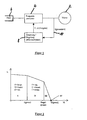
- FIG. 1 shows schematically the basic structure of the engine control in a power tool according to the invention.
- the motor 2 an asynchronous electric motor or a brushless synchronous electric motor, is connected to a mains voltage supplied frequency converter 4, from which it receives the motor supply or motor excitation voltage.
- the Freqenzumrichter 4 is connected to the normal power grid 6 with z. B. 230 V / 50Hz connected.
- a microprocessor-operated motor control device 8 is provided, which drives the frequency converter 4 and gives the specification for the frequency of the motor excitation voltage and for the size of the motor excitation voltage to the frequency converter 4.
- a current collector 10 is in a respective drive line between frequency converter 4 and electric motor 2 is provided.
- This may advantageously be a shunt resistor 12, by means of which known per se and therefore not shown electronic tap circuits generates a motor current corresponding size and the engine control unit 8 can be entered as an input.
- the frequency converter 4, the motor control device 8 and the Stromwertauf choir 10 with circuit not shown are arranged or housed in a machine housing of the power tool on a common board or in a protected against moisture electronics housing as an assembly.
- Figure 2 shows an engine diagram, wherein the engine speed N is plotted as a function of the engine torque M, ie as a function of the load of the electric motor. Up to a limiting current I (limit) , the frequency of the motor exciter voltage and also the magnitude of this voltage is kept constant. Thus, the electric motor runs at approximately constant speed N in the area designated I.
- I limit
- the frequency of the motor excitation voltage is controlled by the motor control device so that the motor current I remains constant, preferably at the limit I (grenz) , which is between 10 and 20 A. , in particular between 10 and 15 A and preferably for example in an angle grinder motor is 12 to 14 A.
- the limit I (grenz) which is between 10 and 20 A. , in particular between 10 and 15 A and preferably for example in an angle grinder motor is 12 to 14 A.
- the frequency of the motor exciter voltage applied to the motor by the frequency converter and thus also the motor speed M.
- the characteristics of a commutator motor are more or less out of the controllable range.
- the power tool according to the invention behaves as users of devices with universal motors are used, so that the speed of the motor noticeably decreases with increasing load. This area is indicated in Fig. 2 with II.
Landscapes
- Engineering & Computer Science (AREA)
- Power Engineering (AREA)
- Control Of Motors That Do Not Use Commutators (AREA)
- Control Of Ac Motors In General (AREA)
- Surgical Instruments (AREA)
- Electrical Discharge Machining, Electrochemical Machining, And Combined Machining (AREA)
Claims (18)
- Appareil-outil électrique, en particulier appareil-outil portatif électrique, comprenant un moteur électrique asynchrone (2) ou un moteur électrique synchrone sans brosse et un dispositif de commande de moteur (8) assisté par ordinateur, caractérisé par un convertisseur de fréquence (4) pouvant être commandé par le dispositif de commande de moteur, au moyen duquel une tension (excitatrice) de moteur peut être appliquée au moteur (2), et par un enregistreur de courant (10) détectant le courant du moteur et coopérant avec le dispositif de commande du moteur (8), et par le fait que le dispositif de commande du moteur (8) est conçu de telle sorte que, dans une première phase de l'exploitation du moteur, dans le cas de courants du moteur allant jusqu'à un courant limite I(grenz), la tension appliquée au moteur et la fréquence du courant du moteur sont maintenues constantes et en ce que, dans une seconde phase d'exploitation du moteur, en cas de charges supérieures à la charge à laquelle le courant du moteur atteint le courant limite I(grenz), la tension appliquée au moteur est maintenue constante et la fréquence du courant du moteur est diminuée de telle sorte que le courant du moteur est maintenu à une valeur constante.
- Appareil-outil électrique selon la revendication 1, caractérisé en ce que le dispositif de commande du moteur (8) est conçu de telle sorte que le courant du moteur est maintenu pendant la seconde phase à la valeur I(grenz) constante.
- Appareil-outil électrique selon la revendication 1 ou 2, caractérisé en ce que le dispositif de commande du moteur (8) est conçu de telle sorte que la tension appliquée au moteur est maintenue à la même valeur pendant la première et la seconde phases.
- Appareil-outil électrique selon l'une quelconque ou plusieurs des revendications précédentes, caractérisé en ce que l'enregistreur de courant (10) comprend une résistance de shunt (12).
- Appareil-outil électrique selon l'une quelconque ou plusieurs des revendications précédentes, caractérisé en ce que le convertisseur de fréquence (4) et le dispositif de commande du moteur (8) sont logés dans le boîtier de l'appareil-outil électrique.
- Appareil-outil électrique selon l'une quelconque ou plusieurs des revendications précédentes, caractérisé en ce que le courant limite I(grenz) est choisi entre 4 et 20 A, en particulier entre 10 et 15 A.
- Appareil-outil électrique selon l'une quelconque ou plusieurs des revendications précédentes, caractérisé en ce que le convertisseur de fréquence (4) et le dispositif de commande du moteur (8) sont réalisés sur une platine commune et/ou sont disposés dans un boîtier électronique fermé.
- Appareil-outil électrique selon l'une quelconque ou plusieurs des revendications précédentes, caractérisé en ce que le dispositif de commande du moteur (8) est réalisé de telle sorte que, pendant une troisième phase d'exploitation du moteur, qui est caractérisée par le fait que le courant du moteur ne peut plus être maintenu constant uniquement par l'abaissement de la fréquence du courant du moteur lorsque la charge augmente à nouveau, la tension du moteur est abaissée également.
- Appareil-outil électrique selon la revendication 8, caractérisé en ce que le dispositif de commande du moteur (8) est réalisé de telle sorte que le moteur est déconnecté lorsqu'on atteint une tension de moteur U(grenz) pendant la troisième phase.
- Appareil-outil électrique selon la revendication 8, caractérisé en ce que le dispositif de commande du moteur (8) est réalisé de telle sorte que, lorsqu'on atteint une tension de moteur U(grenz) pendant la troisième phase, on applique une excitation résiduelle au moteur au lieu d'une déconnexion du moteur, pour que, après la suppression de la charge, le moteur redémarre automatiquement.
- Procédé pour l'exploitation d'un appareil-outil électrique, en particulier d'un appareil-outil portatif électrique avec un moteur électrique asynchrone ou un moteur électrique synchrone sans brosse et un dispositif de commande du moteur (8) assisté par ordinateur, caractérisé en ce que pendant une première phase d'exploitation du moteur, avec une faible charge en cas de courants du moteur allant jusqu'à un courant limite I(grenz), la tension appliquée au moteur et la fréquence du courant du moteur sont maintenues constantes et en ce que, pendant une seconde phase d'exploitation du moteur, en cas de charges supérieures à la charge à laquelle le courant du moteur atteint le courant limite I(grenz), la tension appliquée au moteur est maintenue constante et la fréquence du courant du moteur est abaissée de telle sorte que le courant du moteur est maintenu sur une valeur constante.
- Procédé selon la revendication 11, caractérisé en ce que le courant du moteur est maintenu à la valeur I(grenz) constante pendant la seconde phase.
- Procédé selon la revendication 11 ou 12, caractérisé en ce que la tension appliquée au moteur est maintenue à une valeur constante pendant la seconde phase.
- Procédé selon la revendication 11, 12 ou 13, caractérisé en ce que la tension appliquée au moteur est maintenue à une valeur constante, en particulier la même valeur, pendant la première et la seconde phases.
- Procédé selon l'une quelconque ou plusieurs des revendications 11 à 14, caractérisé en ce que le courant limite I(grenz) est choisi entre 10 et 20 A, en particulier entre 10 et 15 A.
- Procédé selon l'une quelconque ou plusieurs des revendications 11 à 15, caractérisé en ce que, pendant une troisième phase d'exploitation du moteur, qui est caractérisée en ce que le courant du moteur ne peut plus être maintenu constant uniquement par l'abaissement de la fréquence du courant du moteur dans le cas d'une charge à nouveau croissante, la tension du moteur est également abaissée.
- Procédé selon la revendication 16, caractérisé en ce que le moteur est déconnecté lorsqu'on atteint une tension du moteur U(grenz) pendant la troisième phase.
- Procédé selon la revendication 16, caractérisé en ce que, lorsqu'on atteint une tension du moteur U(grenz) pendant la troisième phase, une excitation résiduelle est appliquée au moteur au lieu d'une déconnexion du moteur, pour que, après la suppression de la charge, le moteur redémarre automatiquement.
Applications Claiming Priority (3)
| Application Number | Priority Date | Filing Date | Title |
|---|---|---|---|
| DE10216836 | 2002-04-16 | ||
| DE2002116836 DE10216836B4 (de) | 2002-04-16 | 2002-04-16 | Elektrowerkzeuggerät |
| PCT/EP2003/003111 WO2003088470A1 (fr) | 2002-04-16 | 2003-03-26 | Machine-outil electronique |
Publications (2)
| Publication Number | Publication Date |
|---|---|
| EP1518316A1 EP1518316A1 (fr) | 2005-03-30 |
| EP1518316B1 true EP1518316B1 (fr) | 2007-01-03 |
Family
ID=28798446
Family Applications (1)
| Application Number | Title | Priority Date | Filing Date |
|---|---|---|---|
| EP20030714880 Expired - Lifetime EP1518316B1 (fr) | 2002-04-16 | 2003-03-26 | Machine-outil electronique |
Country Status (7)
| Country | Link |
|---|---|
| US (1) | US7268509B2 (fr) |
| EP (1) | EP1518316B1 (fr) |
| AT (1) | ATE350806T1 (fr) |
| AU (1) | AU2003219098A1 (fr) |
| DE (2) | DE10216836B4 (fr) |
| ES (1) | ES2279942T3 (fr) |
| WO (1) | WO2003088470A1 (fr) |
Families Citing this family (5)
| Publication number | Priority date | Publication date | Assignee | Title |
|---|---|---|---|---|
| DE102006051507A1 (de) * | 2006-10-31 | 2008-05-08 | Kaltenbach & Voigt Gmbh | Steuervorrichtung für den Antrieb eines mit einem geregelten Elektromotor betriebenen Dentalhandstückes |
| US8212511B2 (en) * | 2008-10-22 | 2012-07-03 | Kelsey-Hayes Company | Method and apparatus for limiting torque in an electric drive motor |
| CN103368480B (zh) * | 2012-03-31 | 2016-11-16 | 苏州宝时得电动工具有限公司 | 手持电动工具及其控制方法 |
| CN103368483B (zh) * | 2012-03-31 | 2016-02-17 | 苏州宝时得电动工具有限公司 | 手持电动工具及其控制方法 |
| US11689124B2 (en) | 2021-01-12 | 2023-06-27 | Snap-On Incorporated | Controlling brushless motor commutation |
Family Cites Families (10)
| Publication number | Priority date | Publication date | Assignee | Title |
|---|---|---|---|---|
| DE3125157A1 (de) * | 1981-06-26 | 1983-01-13 | Licentia Patent-Verwaltungs-Gmbh, 6000 Frankfurt | Drehzahlregelschaltung fuer einen motor |
| DK1984A (da) * | 1984-01-03 | 1985-07-04 | Grundfos As | Fremgangsmaade til regulering af en vekselstroemsmotor |
| DE3709983A1 (de) * | 1987-03-26 | 1988-10-13 | Festo Kg | Stromversorgungseinrichtung fuer elektrowerkzeuge |
| DE19629564C2 (de) * | 1996-07-15 | 2000-10-19 | Glibitski Marks | Kleiner Hochleistungselektroantrieb für Asynchron-, Synchron -und andere Wechselstrommotoren |
| WO1999003193A1 (fr) * | 1997-07-11 | 1999-01-21 | Barmag Ag | Procede pour commander un moteur electrique |
| DE29809768U1 (de) * | 1998-05-20 | 1999-09-23 | Elektra Beckum Ag, 49716 Meppen | Tragbare Werkzeugmaschine, insbesondere Tischkreissäge |
| US6166502A (en) * | 1999-04-01 | 2000-12-26 | Delphi Technologies, Inc. | Thermal current limiting apparatus and method for vehicle system with electric motor actuator |
| DE19944194A1 (de) | 1999-09-15 | 2001-03-22 | Bosch Gmbh Robert | Elektronisch kommutierbarer Motor mit Überlastschutz |
| JP2002199773A (ja) * | 2000-12-27 | 2002-07-12 | Sanden Corp | 圧縮機モータ駆動制御方法及び圧縮機駆動用インバータ装置 |
| JP4055992B2 (ja) * | 2002-12-25 | 2008-03-05 | サンデン株式会社 | インバータの電流検出装置 |
-
2002
- 2002-04-16 DE DE2002116836 patent/DE10216836B4/de not_active Expired - Fee Related
-
2003
- 2003-03-26 US US10/510,693 patent/US7268509B2/en not_active Expired - Lifetime
- 2003-03-26 WO PCT/EP2003/003111 patent/WO2003088470A1/fr not_active Ceased
- 2003-03-26 EP EP20030714880 patent/EP1518316B1/fr not_active Expired - Lifetime
- 2003-03-26 AT AT03714880T patent/ATE350806T1/de active
- 2003-03-26 AU AU2003219098A patent/AU2003219098A1/en not_active Abandoned
- 2003-03-26 DE DE50306198T patent/DE50306198D1/de not_active Expired - Lifetime
- 2003-03-26 ES ES03714880T patent/ES2279942T3/es not_active Expired - Lifetime
Also Published As
| Publication number | Publication date |
|---|---|
| US20050162112A1 (en) | 2005-07-28 |
| AU2003219098A1 (en) | 2003-10-27 |
| EP1518316A1 (fr) | 2005-03-30 |
| ES2279942T3 (es) | 2007-09-01 |
| WO2003088470A1 (fr) | 2003-10-23 |
| DE10216836B4 (de) | 2005-09-22 |
| DE10216836A1 (de) | 2003-11-06 |
| ATE350806T1 (de) | 2007-01-15 |
| US7268509B2 (en) | 2007-09-11 |
| DE50306198D1 (de) | 2007-02-15 |
Similar Documents
| Publication | Publication Date | Title |
|---|---|---|
| DE3247046A1 (de) | Verfahren und einrichtung zum speisen einer handgefuehrten werkzeugmaschine mit einem kollektorlosen elektromotor | |
| CH621656A5 (fr) | ||
| EP2087571A1 (fr) | Convertisseur à angle de phase commandable | |
| DE102005024068A1 (de) | Verfahren zur Steuerung eines aus einem Gleichspannungsnetz gespeisten Elektromotors | |
| EP2244372B1 (fr) | Dispositif de circuit pour une installation éolienne | |
| EP1518316B1 (fr) | Machine-outil electronique | |
| DE3900219C2 (de) | Fahrzeugsitz mit motorbetriebener Verstellung der Rückenlehne und der Sitzschiene | |
| EP0283945A2 (fr) | Dispositif d'alimentation en courant électrique pour outillages électriques | |
| DE4442151A1 (de) | Schaltungsanordnung zum Steuern eines elektronisch kommutierten Motors | |
| EP2085191B1 (fr) | Appareil d'entraînement pour outils, de préférence pour outils de carottage | |
| DE4201005C2 (de) | Schaltungsanordnung zum netzunabhängigen, aussetzerfreien Bremsen eines Reihenschlußmotors | |
| DE19912121A1 (de) | Reihenschlußmotor | |
| DE112018006979T5 (de) | Elektrischer Kompressor | |
| DE8808570U1 (de) | Vorrichtung mit Einschaltautomatik für ein Nebengerät bei Inbetriebnahme eines Hauptgerätes | |
| DE3442607A1 (de) | Ueberlast-schutzschaltung fuer eine stromrichteranordnung | |
| AT519142B1 (de) | Verfahren und Vorrichtung zum Abbauen elastisch gespeicherter Energie | |
| EP1163716B1 (fr) | Systeme electronique de commande pour outil electrique manuel | |
| DE2310835A1 (de) | Reihenschluss-kommutatormotor | |
| DE3819166A1 (de) | Schaltanordnung zur drehzahlsteuerung eines reihenschlussmotors mit drehmomentabschaltung | |
| EP1022845A2 (fr) | Procédé et dispositif de commande une moteur éléctrique d'un broyeur à documents | |
| DE102007025985B3 (de) | Steuereinrichtung für ein Elektrohandwerkzeug | |
| DE3501947A1 (de) | Elektrowerkzeug, insbesondere winkelschleifer | |
| DE3223655A1 (de) | Einrichtung zur regelung eines wechselstrom-induktionsmotors | |
| EP4002677A1 (fr) | Système de porte pour un véhicule doté d'une battant de porte et procédé de freinage sélectif d'un battant de porte à moteur électrique | |
| DE212023000373U1 (de) | Antriebseinheit für eine Verdunkelungsvorrichtung und Verwendung der Antriebseinheit für eine Verdunkelungsvorrichtung |
Legal Events
| Date | Code | Title | Description |
|---|---|---|---|
| PUAI | Public reference made under article 153(3) epc to a published international application that has entered the european phase |
Free format text: ORIGINAL CODE: 0009012 |
|
| 17P | Request for examination filed |
Effective date: 20050120 |
|
| AK | Designated contracting states |
Kind code of ref document: A1 Designated state(s): AT BE BG CH CY CZ DE DK EE ES FI FR GB GR HU IE IT LI LU MC NL PT RO SE SI SK TR |
|
| AX | Request for extension of the european patent |
Extension state: AL LT LV MK |
|
| GRAP | Despatch of communication of intention to grant a patent |
Free format text: ORIGINAL CODE: EPIDOSNIGR1 |
|
| RIC1 | Information provided on ipc code assigned before grant |
Ipc: H02P 3/18 20060101AFI20060607BHEP |
|
| GRAS | Grant fee paid |
Free format text: ORIGINAL CODE: EPIDOSNIGR3 |
|
| GRAA | (expected) grant |
Free format text: ORIGINAL CODE: 0009210 |
|
| AK | Designated contracting states |
Kind code of ref document: B1 Designated state(s): AT BE BG CH CY CZ DE DK EE ES FI FR GB GR HU IE IT LI LU MC NL PT RO SE SI SK TR |
|
| PG25 | Lapsed in a contracting state [announced via postgrant information from national office to epo] |
Ref country code: NL Free format text: LAPSE BECAUSE OF FAILURE TO SUBMIT A TRANSLATION OF THE DESCRIPTION OR TO PAY THE FEE WITHIN THE PRESCRIBED TIME-LIMIT Effective date: 20070103 Ref country code: IE Free format text: LAPSE BECAUSE OF FAILURE TO SUBMIT A TRANSLATION OF THE DESCRIPTION OR TO PAY THE FEE WITHIN THE PRESCRIBED TIME-LIMIT Effective date: 20070103 Ref country code: SI Free format text: LAPSE BECAUSE OF FAILURE TO SUBMIT A TRANSLATION OF THE DESCRIPTION OR TO PAY THE FEE WITHIN THE PRESCRIBED TIME-LIMIT Effective date: 20070103 Ref country code: FI Free format text: LAPSE BECAUSE OF FAILURE TO SUBMIT A TRANSLATION OF THE DESCRIPTION OR TO PAY THE FEE WITHIN THE PRESCRIBED TIME-LIMIT Effective date: 20070103 Ref country code: DK Free format text: LAPSE BECAUSE OF FAILURE TO SUBMIT A TRANSLATION OF THE DESCRIPTION OR TO PAY THE FEE WITHIN THE PRESCRIBED TIME-LIMIT Effective date: 20070103 |
|
| REG | Reference to a national code |
Ref country code: GB Ref legal event code: FG4D Free format text: NOT ENGLISH |
|
| REF | Corresponds to: |
Ref document number: 50306198 Country of ref document: DE Date of ref document: 20070215 Kind code of ref document: P |
|
| REG | Reference to a national code |
Ref country code: IE Ref legal event code: FG4D Free format text: LANGUAGE OF EP DOCUMENT: GERMAN |
|
| GBT | Gb: translation of ep patent filed (gb section 77(6)(a)/1977) |
Effective date: 20070207 |
|
| PG25 | Lapsed in a contracting state [announced via postgrant information from national office to epo] |
Ref country code: SE Free format text: LAPSE BECAUSE OF FAILURE TO SUBMIT A TRANSLATION OF THE DESCRIPTION OR TO PAY THE FEE WITHIN THE PRESCRIBED TIME-LIMIT Effective date: 20070403 |
|
| PG25 | Lapsed in a contracting state [announced via postgrant information from national office to epo] |
Ref country code: BG Free format text: LAPSE BECAUSE OF EXPIRATION OF PROTECTION Effective date: 20070404 |
|
| PG25 | Lapsed in a contracting state [announced via postgrant information from national office to epo] |
Ref country code: PT Free format text: LAPSE BECAUSE OF FAILURE TO SUBMIT A TRANSLATION OF THE DESCRIPTION OR TO PAY THE FEE WITHIN THE PRESCRIBED TIME-LIMIT Effective date: 20070604 |
|
| NLV1 | Nl: lapsed or annulled due to failure to fulfill the requirements of art. 29p and 29m of the patents act | ||
| ET | Fr: translation filed | ||
| REG | Reference to a national code |
Ref country code: IE Ref legal event code: FD4D |
|
| REG | Reference to a national code |
Ref country code: ES Ref legal event code: FG2A Ref document number: 2279942 Country of ref document: ES Kind code of ref document: T3 |
|
| PLBE | No opposition filed within time limit |
Free format text: ORIGINAL CODE: 0009261 |
|
| STAA | Information on the status of an ep patent application or granted ep patent |
Free format text: STATUS: NO OPPOSITION FILED WITHIN TIME LIMIT |
|
| PG25 | Lapsed in a contracting state [announced via postgrant information from national office to epo] |
Ref country code: SK Free format text: LAPSE BECAUSE OF FAILURE TO SUBMIT A TRANSLATION OF THE DESCRIPTION OR TO PAY THE FEE WITHIN THE PRESCRIBED TIME-LIMIT Effective date: 20070103 |
|
| 26N | No opposition filed |
Effective date: 20071005 |
|
| BERE | Be: lapsed |
Owner name: METABOWERKE G.M.B.H. Effective date: 20070331 |
|
| PG25 | Lapsed in a contracting state [announced via postgrant information from national office to epo] |
Ref country code: BE Free format text: LAPSE BECAUSE OF NON-PAYMENT OF DUE FEES Effective date: 20070331 Ref country code: CZ Free format text: LAPSE BECAUSE OF FAILURE TO SUBMIT A TRANSLATION OF THE DESCRIPTION OR TO PAY THE FEE WITHIN THE PRESCRIBED TIME-LIMIT Effective date: 20070103 Ref country code: RO Free format text: LAPSE BECAUSE OF FAILURE TO SUBMIT A TRANSLATION OF THE DESCRIPTION OR TO PAY THE FEE WITHIN THE PRESCRIBED TIME-LIMIT Effective date: 20070103 |
|
| PG25 | Lapsed in a contracting state [announced via postgrant information from national office to epo] |
Ref country code: MC Free format text: LAPSE BECAUSE OF NON-PAYMENT OF DUE FEES Effective date: 20070331 |
|
| PG25 | Lapsed in a contracting state [announced via postgrant information from national office to epo] |
Ref country code: GR Free format text: LAPSE BECAUSE OF FAILURE TO SUBMIT A TRANSLATION OF THE DESCRIPTION OR TO PAY THE FEE WITHIN THE PRESCRIBED TIME-LIMIT Effective date: 20070404 |
|
| PG25 | Lapsed in a contracting state [announced via postgrant information from national office to epo] |
Ref country code: EE Free format text: LAPSE BECAUSE OF FAILURE TO SUBMIT A TRANSLATION OF THE DESCRIPTION OR TO PAY THE FEE WITHIN THE PRESCRIBED TIME-LIMIT Effective date: 20070103 |
|
| PG25 | Lapsed in a contracting state [announced via postgrant information from national office to epo] |
Ref country code: CY Free format text: LAPSE BECAUSE OF FAILURE TO SUBMIT A TRANSLATION OF THE DESCRIPTION OR TO PAY THE FEE WITHIN THE PRESCRIBED TIME-LIMIT Effective date: 20070103 |
|
| PG25 | Lapsed in a contracting state [announced via postgrant information from national office to epo] |
Ref country code: LU Free format text: LAPSE BECAUSE OF NON-PAYMENT OF DUE FEES Effective date: 20070326 |
|
| PG25 | Lapsed in a contracting state [announced via postgrant information from national office to epo] |
Ref country code: HU Free format text: LAPSE BECAUSE OF FAILURE TO SUBMIT A TRANSLATION OF THE DESCRIPTION OR TO PAY THE FEE WITHIN THE PRESCRIBED TIME-LIMIT Effective date: 20070704 Ref country code: TR Free format text: LAPSE BECAUSE OF FAILURE TO SUBMIT A TRANSLATION OF THE DESCRIPTION OR TO PAY THE FEE WITHIN THE PRESCRIBED TIME-LIMIT Effective date: 20070103 |
|
| PGFP | Annual fee paid to national office [announced via postgrant information from national office to epo] |
Ref country code: AT Payment date: 20110323 Year of fee payment: 9 Ref country code: CH Payment date: 20110328 Year of fee payment: 9 |
|
| PGFP | Annual fee paid to national office [announced via postgrant information from national office to epo] |
Ref country code: ES Payment date: 20110324 Year of fee payment: 9 |
|
| PGFP | Annual fee paid to national office [announced via postgrant information from national office to epo] |
Ref country code: IT Payment date: 20110331 Year of fee payment: 9 |
|
| REG | Reference to a national code |
Ref country code: CH Ref legal event code: PL |
|
| REG | Reference to a national code |
Ref country code: AT Ref legal event code: MM01 Ref document number: 350806 Country of ref document: AT Kind code of ref document: T Effective date: 20120326 |
|
| PG25 | Lapsed in a contracting state [announced via postgrant information from national office to epo] |
Ref country code: LI Free format text: LAPSE BECAUSE OF NON-PAYMENT OF DUE FEES Effective date: 20120331 Ref country code: CH Free format text: LAPSE BECAUSE OF NON-PAYMENT OF DUE FEES Effective date: 20120331 Ref country code: AT Free format text: LAPSE BECAUSE OF NON-PAYMENT OF DUE FEES Effective date: 20120326 |
|
| PG25 | Lapsed in a contracting state [announced via postgrant information from national office to epo] |
Ref country code: IT Free format text: LAPSE BECAUSE OF NON-PAYMENT OF DUE FEES Effective date: 20120326 |
|
| REG | Reference to a national code |
Ref country code: ES Ref legal event code: FD2A Effective date: 20130710 |
|
| PG25 | Lapsed in a contracting state [announced via postgrant information from national office to epo] |
Ref country code: ES Free format text: LAPSE BECAUSE OF NON-PAYMENT OF DUE FEES Effective date: 20120327 |
|
| REG | Reference to a national code |
Ref country code: DE Ref legal event code: R082 Ref document number: 50306198 Country of ref document: DE Representative=s name: LORENZ & KOLLEGEN PATENTANWAELTE PARTNERSCHAFT, DE |
|
| REG | Reference to a national code |
Ref country code: FR Ref legal event code: PLFP Year of fee payment: 14 |
|
| REG | Reference to a national code |
Ref country code: FR Ref legal event code: PLFP Year of fee payment: 15 |
|
| REG | Reference to a national code |
Ref country code: FR Ref legal event code: PLFP Year of fee payment: 16 |
|
| PGFP | Annual fee paid to national office [announced via postgrant information from national office to epo] |
Ref country code: FR Payment date: 20210319 Year of fee payment: 19 |
|
| PGFP | Annual fee paid to national office [announced via postgrant information from national office to epo] |
Ref country code: DE Payment date: 20210323 Year of fee payment: 19 Ref country code: GB Payment date: 20210324 Year of fee payment: 19 |
|
| REG | Reference to a national code |
Ref country code: DE Ref legal event code: R119 Ref document number: 50306198 Country of ref document: DE |
|
| GBPC | Gb: european patent ceased through non-payment of renewal fee |
Effective date: 20220326 |
|
| PG25 | Lapsed in a contracting state [announced via postgrant information from national office to epo] |
Ref country code: GB Free format text: LAPSE BECAUSE OF NON-PAYMENT OF DUE FEES Effective date: 20220326 Ref country code: FR Free format text: LAPSE BECAUSE OF NON-PAYMENT OF DUE FEES Effective date: 20220331 Ref country code: DE Free format text: LAPSE BECAUSE OF NON-PAYMENT OF DUE FEES Effective date: 20221001 |