EP1518383B1 - Verfahren und vorrichtung zum senden und/oder zum empfang von informationen in verbindung mit einem fahrzeug - Google Patents
Verfahren und vorrichtung zum senden und/oder zum empfang von informationen in verbindung mit einem fahrzeug Download PDFInfo
- Publication number
- EP1518383B1 EP1518383B1 EP03756942A EP03756942A EP1518383B1 EP 1518383 B1 EP1518383 B1 EP 1518383B1 EP 03756942 A EP03756942 A EP 03756942A EP 03756942 A EP03756942 A EP 03756942A EP 1518383 B1 EP1518383 B1 EP 1518383B1
- Authority
- EP
- European Patent Office
- Prior art keywords
- vehicle
- server
- client
- information
- diagnostic
- Prior art date
- Legal status (The legal status is an assumption and is not a legal conclusion. Google has not performed a legal analysis and makes no representation as to the accuracy of the status listed.)
- Expired - Lifetime
Links
- 238000000034 method Methods 0.000 title claims description 28
- 238000013515 script Methods 0.000 claims description 62
- 230000006854 communication Effects 0.000 claims description 58
- 238000004891 communication Methods 0.000 claims description 55
- 238000004171 remote diagnosis Methods 0.000 claims description 21
- 230000009471 action Effects 0.000 claims description 5
- 238000004590 computer program Methods 0.000 claims 2
- 230000006870 function Effects 0.000 description 16
- 230000005540 biological transmission Effects 0.000 description 13
- 230000008569 process Effects 0.000 description 11
- 238000003745 diagnosis Methods 0.000 description 9
- 230000015654 memory Effects 0.000 description 9
- 238000002405 diagnostic procedure Methods 0.000 description 8
- 230000004913 activation Effects 0.000 description 7
- 230000007246 mechanism Effects 0.000 description 6
- 238000012790 confirmation Methods 0.000 description 5
- 238000012423 maintenance Methods 0.000 description 5
- 230000004044 response Effects 0.000 description 5
- 238000012546 transfer Methods 0.000 description 4
- 238000011156 evaluation Methods 0.000 description 2
- 230000000977 initiatory effect Effects 0.000 description 2
- 238000012544 monitoring process Methods 0.000 description 2
- 238000012545 processing Methods 0.000 description 2
- 238000012800 visualization Methods 0.000 description 2
- 241000599985 Beijerinckia mobilis Species 0.000 description 1
- 230000015556 catabolic process Effects 0.000 description 1
- 230000001413 cellular effect Effects 0.000 description 1
- 238000006243 chemical reaction Methods 0.000 description 1
- 230000006835 compression Effects 0.000 description 1
- 238000007906 compression Methods 0.000 description 1
- 230000001419 dependent effect Effects 0.000 description 1
- 238000010586 diagram Methods 0.000 description 1
- 230000002349 favourable effect Effects 0.000 description 1
- 238000010438 heat treatment Methods 0.000 description 1
- 230000003993 interaction Effects 0.000 description 1
- 230000008092 positive effect Effects 0.000 description 1
- 230000009467 reduction Effects 0.000 description 1
- 238000000638 solvent extraction Methods 0.000 description 1
- 230000002123 temporal effect Effects 0.000 description 1
- 230000001960 triggered effect Effects 0.000 description 1
Images


Classifications
-
- G—PHYSICS
- G07—CHECKING-DEVICES
- G07C—TIME OR ATTENDANCE REGISTERS; REGISTERING OR INDICATING THE WORKING OF MACHINES; GENERATING RANDOM NUMBERS; VOTING OR LOTTERY APPARATUS; ARRANGEMENTS, SYSTEMS OR APPARATUS FOR CHECKING NOT PROVIDED FOR ELSEWHERE
- G07C5/00—Registering or indicating the working of vehicles
- G07C5/008—Registering or indicating the working of vehicles communicating information to a remotely located station
-
- H—ELECTRICITY
- H04—ELECTRIC COMMUNICATION TECHNIQUE
- H04L—TRANSMISSION OF DIGITAL INFORMATION, e.g. TELEGRAPHIC COMMUNICATION
- H04L67/00—Network arrangements or protocols for supporting network services or applications
- H04L67/01—Protocols
- H04L67/02—Protocols based on web technology, e.g. hypertext transfer protocol [HTTP]
- H04L67/025—Protocols based on web technology, e.g. hypertext transfer protocol [HTTP] for remote control or remote monitoring of applications
Definitions
- the invention relates to a method and apparatus for transmitting, transmitting and / or receiving information in connection with a vehicle, in particular for remote diagnosis, remote control and / or remote control of a component / function of the vehicle.
- a method and a device for transmitting, transmitting and / or receiving information in connection with a vehicle finds a data exchange via a telecommunication network and / or a data network for the realization of a remote maintenance, a remote diagnosis and / or a remote control of a Motor vehicle, one of its components and / or functions instead.
- a telecommunications network while a mobile network is proposed according to the GSM standard or the UMTS standard, while the Internet is mentioned as an example of the data network.
- References to the specific embodiment, in particular with regard to flexibility and / or reliability and / or security of the information exchange and / or with regard to the effort reduction, especially in the terminals in the vehicle are not given.
- the document "Ertico, Telematics Forum Brochure, 4/2002 shows a procedure for communication between a vehicle-side client and a network-side server via a WAP interface, whereby information is transferred from the server to the client as part of a diagnosis.
- FIG. 10 shows a system and method for vehicle diagnostics that provides a vehicle-side client connected to a vehicle monitoring system and remote communication to a server.
- WAP protocol since its powerful transmission and / or security mechanisms for the specific application in the mobile sector, in particular for the said vehicle-related telematics applications such as the remote diagnosis of motor vehicle control units, can be used.
- Another positive effect of using this protocol is that resources such as memory and computing power are saved on the terminals, since this protocol is designed specifically for terminals with low resources. Using this protocol will not require additional functional units for data transfer and content visualization. This is achieved solely by using a known WAP browser and the associated WAP communication stack. Particularly favorable in terms of saving resources in the terminal, the use of the WAP protocol, if this is already present in the terminal for other services, such. B. mobile internet. The synergy achieved by using the protocol is therefore considerable.
- the WAP browser in the terminal are provided by the server.
- the WML pages can also contain so-called WML scripts, which allow the description of more complex processes in the terminal. Parts of the terminal applications such. For example, remote diagnostics do not have to be explicitly implemented there, but have already been implemented in the WAP stack and can be used universally.
- the WAP standard provides an interface (EFI interface) with the aid of which the WAP browser (and thus indirectly the server) can communicate with independent, external applications on the mobile terminal via a standardized functional interface.
- EFI interface an interface
- the WAP browser and thus indirectly the server
- independent, external applications on the mobile terminal via a standardized functional interface.
- a protocol standard adapted to mobile applications shows particularly advantageous results in connection with automotive telematics services over cellular networks.
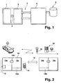
- FIG. 1 shows an overview image of a system for a vehicle-related telematics service, while based FIG. 2 an implementation example of such a system based on the WAP protocol is shown.
- FIG. 3 shows a suitable embodiment of transmission steps via the interface between telematics terminal and server.
- the FIGS. 4 and 5 show flowcharts showing the program sequences in the telematics terminal or in the server using the example of in FIG. 3 Outline the communication shown.
- FIG. 1 shows an overview image of a system for a vehicle-related telematics service, where information between a vehicle (there terminal) and a server via a mobile network or via a data network, such as the Internet, are exchanged.
- a vehicle there terminal
- a server via a mobile network or via a data network, such as the Internet
- Remote action or remote interrogation essentially refers to the remote control of vehicle functions, in particular comfort functions such as switching on the auxiliary heating, etc., as well as the interrogation of vehicle states and / or operating parameters.
- the user initiates communication with the vehicle via a central server or communicates directly with the vehicle.
- Remote diagnostics includes the remote reading of diagnostic data from the vehicle, their analysis and, if necessary, the generation of a recommendation for further action.
- a central server which is in communication with the vehicle via a mobile network, via a wired network and / or via a data network such as the Internet with the motor vehicle.
- a mobile network via a wired network and / or via a data network such as the Internet with the motor vehicle.
- a data network such as the Internet with the motor vehicle.
- the so-called software download or remote flashing should be mentioned as a function of which new program code or parameters are applied to software-configurable systems in the vehicle, for example control units, in order to increase the functionalities or the performance increase.
- communication takes place via a mobile radio network, a wired network and / or, for example, the Internet, starting from a central computer (server) or service center.
- Remote maintenance is essentially the monitoring of the vehicle condition and the access to the maintenance data in the vehicle from a central point to check whether, when and what measures to maintain the target state are performed.
- An example of this is the dynamic adjustment of maintenance intervals. In general, these functionalities are subsumed under the concept of vehicle-related remote control.
- All said functions or services are realized via the interface described below between the motor vehicle (there the terminal) and a central computer, in particular a server in a service center or the vehicle manufacturer or the component supplier. If necessary, the control of components and / or functions in the vehicle via a below also described interface between the terminal and the affected vehicle component.
- a central computer in particular a server in a service center or the vehicle manufacturer or the component supplier.
- the control of components and / or functions in the vehicle via a below also described interface between the terminal and the affected vehicle component.
- the execution of the service "Remote Diagnosis" is shown, in a similar manner, the application of the interface is also used in conjunction with many other services, such. B. the above.
- FIG. 1 shows an overview of a remote diagnostic system.
- the vehicle electronics for example, a control unit network is shown, which is connected via a predetermined interface 2 with the vehicle-side part 3 of the remote diagnostic system, in particular with a telematics terminal.
- This vehicle-side application uses the integrated in the vehicle electronics diagnostic mechanisms (onboard diagnostics), for example, to capture error memory contents.
- the vehicle-side part of the remote diagnosis system 3 accesses the vehicle network via the interface 2, for example via a CAN bus or a K-line, and thus to the vehicle electronics 1 or the control devices to be diagnosed.
- the described vehicle-side part is connected via a further interface 4 with the central part 5 of the remote diagnostic system.
- This central part preferably represents the server or the computer system of a service center.
- this server processes as many of the tasks as possible in the remote diagnosis, so that as few resources as possible need to be reserved in the vehicle terminal. For example, it essentially takes over the configuration of the diagnostic unit in the vehicle at the beginning of the diagnosis, the control of this unit during the process and the evaluation of the determined data. For this purpose, he uses in particular vehicle-specific data and commands which are stored in the data memory 6.
- the server is an internet server.
- the transmission link 4 between server and client is in the preferred embodiment, because of the properties in terms of coverage, availability and cost a mobile interface.
- the protocol used in connection with the remote diagnosis for information exchange is a standardized protocol, which is adapted to the specific request of a mobile network.
- the wireless application protocol (WAP) has proven to be suitable.
- the WAP is a worldwide standardized communication of mobile terminals with stationary computers on the Internet. It consists of several individual protocols that describe the complete communication process.
- Each WAP-enabled device has a special WAP browser for the interpretation and visualization of standardized transmission content.
- the transmitted contents are realized in the form of WML pages. These pages may also contain so-called WML scripts, which allow the description of more complex processes in the terminal.
- EFI interface standardized functional interface
- the security mechanisms of the protocol are used in the specific application for the remote diagnosis of motor vehicles or motor vehicle components.
- no additional functional units in the terminal to ensure the security of the data transfer and / or to provide access rights are necessary.
- FIG. 2 shows a diagram illustrating an implementation of a remote diagnostic system with WAP communication.
- the vehicle-side part 10 (terminal) essentially consists of a module 10a, which includes the functionalities of the diagnostic application, a module 10c, the WAP browser and a communication module 10d, which sends information to the mobile network and receives from there.
- the module 10a is connected to other control units and / or components of the vehicle via a bus system 12 (diagnostic bus), for example a CAN bus. Information, data and / or commands are exchanged via these interfaces.
- a further interface 10b (EFI interface)
- the module 10a is linked to the web browser 10c.
- the communication module 10d transmits or receives data via a transmitter or receiver 14, for example a mobile radio device, to or via the air interface 16.
- a transmitter or receiver 14 for example a mobile radio device
- the air interface 16 for example a mobile radio device
- the vehicle-side part of the system is integrated in one embodiment in a telematics terminal.
- This also includes the described GSM module for mobile traffic and the WAP stack for the Internet functionality.
- the connection to the diagnostic bus, mostly via CAN, is also available.
- GSM Global System for Mobile communications
- WAP Mobile standards
- GPRS Global System for Mobile communications
- the central processing unit 18, in particular a web server receives from a transmitting / receiving device 20 of the mobile interface directly or via a gateway computer data from the vehicle side part of the system or sends data at this. If a gateway computer is used on the network side, this forms the WAP gateway (here the WAP stack is implemented). Typically, the dial-in of the mobile device 14 takes place in the Internet in such a gateway.
- the gateway recherzer also includes in particular the communication interface to the mobile radio network as well as the interface to the web server.
- the WAP gateway has the task of implementing a protocol conversion from WAP to the Internet format HTTP and vice versa, on the other hand to carry out a compression and precompiling of the WML pages and scripts obtained by the requested Web server before it is sent back to the mobile subscriber become.
- This gateway function takes over as in FIG. 2 the server 18 itself (module 18a, mobile network interface module 18b) is shown, while in another embodiment, a gateway computer connected to the server via an Internet connection performs the described tasks.
- the web server 18, for example, a service center has the task of the diagnostic server.
- the implemented software in the web server 18 (module 18c) answers the requests of the client (terminal) with dynamically generated response pages and scripts.
- the dynamic generation of the answers takes place with the aid of predefined, server-side scripts (programs) and a database 22 which contains all the data necessary for the identification, configuration and execution of the diagnostic application in the vehicle for the corresponding requestor.
- the tasks of the web server are general web server tasks, eg processing of inquiries, distribution of pages or files to the right recipient, communication management, etc., as well as the superordinate flow control of diagnostics and configuration of the diagnostic application in the client via dynamically generated WML pages and scripts, maintaining and managing the data required for vehicle diagnostics in a database, managing the database itself, the Evaluation of the user data coming from the vehicle, the provision or the dynamic generation of the surface for the Femdiagnoseap bearing in the vehicle.
- the determination of the user data (error memory), that is the diagnosis itself, is carried out according to known diagnostic methods that are implemented in the vehicle.
- WML pages and WML scripts for controlling the diagnostics are transferred from the server to the terminal and processed by it.
- a self-implemented human-machine interface in the vehicle-side part of the system is omitted here, since this is realized by the display of WML pages in the WAP browser.
- FIG. 3 An example of the communication between server 50 and vehicle-side part 52 is based on FIG. 3 shown.
- the initiation of the communication process begins by an operator, for example the driver of the motor vehicle.
- the activation of the Femdiagnosekommunikation by the service center is made.
- the initiation takes place via the server, in which this in advance to display the FIG. 3 as an additional step, prompt the client to establish a communication connection, e.g. B. via an SMS to the client.
- a communication connection e.g. B. via an SMS to the client.
- Such a process is specified in the WAP standard as so-called push / standardized.
- the remote diagnostic unit in the vehicle contains mechanisms and functions for the independent execution of the diagnostic procedures.
- the reading out of ECU error memory for data acquisition is done by remote-controlled functions in the telematics terminal.
- This includes functional units such as the transport protocol layer for CAN bus data, the protocol layer required for the logical diagnostics process and a corresponding sequence control. It is also provided to download the required data for the corresponding protocol layers and for the flow control at the beginning of the diagnostic process from the diagnostic server and to configure the layers using protocol macros and communication parameters.
- the transmission of command is provided at the level of the diagnostic protocol.
- the unit in the vehicle does not independently perform the diagnostic operation, but only passes the data coming from the server to the ECU to be diagnosed.
- diagnostic protocol functionalities in the vehicle are greatly reduced and reduced to a minimum. They remain almost completely in the server.
- the individual diagnostic commands are transmitted transparently via the air interface. Only a few simple structured messages are generated in the vehicle.
- FIG. 3 shows on the left side of the vehicle-side part 52 of the diagnostic system, on the right side of the network-side part 50.
- the arrows represent the flow of information, from top to bottom, a temporal order of the requests and responses in the communication is shown.
- the illustrated communication steps are exemplary. Their number can also be reduced, for example, by combining individual sub-processes in a communication process.
- step C1 the request of a remote diagnostic start page to the service center by the client.
- this message is sent as a URL address stored in the terminal.
- the request is triggered by a corresponding activation of the remote diagnosis by an operator, for example by means of a switch mounted in the vehicle, an input, a command combination, or due to a via mobile (by an operator, the Service center, etc.).
- the response of the server is shown in step S 1.
- the server sends the terminal a WAP page to enable remote diagnostics in the vehicle.
- the page is realized as a WML page.
- the two steps mentioned represent the subtask "Request the remote diagnosis service".
- the client In the next step C2 after receiving the WAP page, the client either automatically or user-initiated requests the transmission of a login page. Their URL was in the previously received page.
- the server then provides the desired login page in step S2, with a reference to a login script.
- the page is also sent here as a WML page with a corresponding script reference.
- information about the loaded login page is optionally output on a display for the user.
- the URL to this is determined by means of the script reference in the WML page.
- the server transmits the requested login script as a WML script for reading the user data in the vehicle.
- the client then sends the data (user identification data) to the server in step C4 with the request for the next WAP page.
- the transmitted user data are then checked in the server and, if these data are correct, the remote diagnosis process is continued, in the other case aborted or step S3 repeated.
- the steps S2 to C4 represent the section user identification and authentication.
- the server starts the remote diagnostics by sending a WAP page (as a WML page with a script reference) in step S4, which, after successful identification of the user, transmits a login confirmation, among other things.
- This WAP page contains a reference to the WML script for the identification of the motor vehicle.
- the transmission of the login confirmation is optionally output as user information on a display.
- the client sends a request of a script for reading the motor vehicle identification data to the server.
- the required URL address is contained in the script reference of step S4.
- the server receives this request and transmits in the context of step S5 as a WML script a script for reading the motor vehicle identification data to the client.
- the corresponding identification data are then read out in the client and together with the request for the next WAP page with data in the step C6 sent to the server.
- the transmitted vehicle identification data (vehicle type, possibly software version, etc.), possibly with GPS position data, are checked in the server. Depending on the data, the diagnostic procedures and the necessary parameters are selected from his database. This completes the sub-step of vehicle identification (S4 to C6) and the next WML page is requested from the server. The URL for this has been transferred to the client in the just executed sub-step.
- the server then sends a diagnostic follow-up page u in step S6.
- a. with status information including a reference to a diagnostic script to the client This is done as a WML page with script reference.
- the diagnosis start is displayed to the user on a display.
- the client Upon receipt of the information in step S6, the client sends the request to the server requesting the transmission of the diagnostic script to read the diagnostic data.
- the URL address is taken from the script reference in step S6.
- the diagnosis script (WML script) is then generated in the server on the basis of this request and transmitted to the client in step S7. Then, executing the diagnostic script, the fault memories are read out on the vehicle side and transmitted to the server with the request of the next WML page in step C8.
- the steps S6 to C8 represent the subarea of the readout of the diagnostic data, which in principle can also take place in several passes, that is, with a plurality of sub-scripts. For example, a script may be provided for each control unit. The sub-process in this area is then performed several times.
- Step S8 thus represents the portion of determining the diagnosis result and its output.
- step C9 the client sends, if necessary, manually initiated another request to the server, with which he requests a WAP page with a follow-up recommendation.
- the URL can either be stored in the terminal or together with the Diagnosis results page be submitted.
- a follow-up recommendation is generated from the database depending on the detected error or the detected errors, a recommendation page is set up and the diagnostic process is ended.
- step S9 the server sends the recommendation page as a WML page to the client.
- the determined follow-up recommendation is output by the client on a display.
- the command for the browser is available to visit the next WML page and load the associated data as well as, if necessary, data determined in the client with the request to transfer to the server.
- these sub-steps can be partially replaced in the order, wherein the sub-step 6 may possibly also be omitted.
- the number or length of the individual communication steps depends on the number of units to be diagnosed in the vehicle.
- the procedure shown is carried out completely automatically at the time of activation of the remote diagnosis until the diagnosis result is output without further interaction with the user.
- the scripts are executed by transmitting predetermined commands via the CAN connection to the ECU to be diagnosed.
- the data determined by this are transmitted via the CAN connection to the client and sent by the latter via the air interface to the server.
- the program according to FIG. 4 is started by a request to initiate remote diagnostics.
- the server sends a predetermined WAP page for activation.
- the server always responds only to incoming requests. Ie. the server is in a kind of "inactive status" as long as no request arrives .. The communication is finished for the server, as soon as no request comes from the client any more.
- the receipt of a request (URL) for a login page is expected. If a request is received, step 103 follows. If no request is received, communication is unsuccessful from the server's perspective.
- the server responds according to the request with the login page and script reference. Then, in step 105, the receipt of a request (URL) for a login script is expected.
- step 106 If a request is received, step 106 follows. If no request is received, the communication is unsuccessful from the server's point of view. In step 106, the server sends a login script according to the request. Subsequently, in step 107, the reception of a request (URL) for a next page as well as the reception of user identification and authentication data is expected. If a request and data are received correctly, step 108 follows. If no request and / or data and / or received is received, the communication is terminated unsuccessfully. In step 108, the user identification and authentication data is checked. If they agree with pre-stored data, ie if the sender is authorized, step 109 follows.
- a WML page is generated for the error message and sent to the client in response to its erroneous request (step 123).
- the communication is finished (step 104).
- step 109 in accordance with the request, the server sends a subsequent page dynamically generated on the basis of the previously received data with confirmation of the login including a script reference to a vehicle identification script.
- step 110 the reception of a request (URL address) for the vehicle identification script is expected.
- step 111 follows. If no request is received, the communication is unsuccessful.
- the server sends the vehicle identification script in accordance with the request. Then, in step 112, the reception of a request (URL address) for a following page including data for the vehicle identification is expected.
- step 113 follows. If there is no request or no data is received the communication ends.
- the server generates a diagnostic script for the corresponding vehicle from its database in accordance with the transmitted vehicle data. If a script can not be generated for the transmitted data, either a standard script is used or the process is terminated (step 124). Then, an error message in the form of a WML page or a reference to it is returned (step 125).
- the server sends a subsequent page in accordance with the request, together with a reference to the diagnostic script (URL address).
- step 115 a request (URL) for the script is expected to be received.
- step 116 follows.
- step 116 the server sends the diagnostic script according to the request. Subsequently, in step 117, the reception of a request (URL address) for a subsequent page together with diagnostic data is expected. If a request including data is received (see step 126), step 118 follows. If no data is received, the communication is aborted / terminated. Then, an error message in the form of a WML page or a reference to it is returned (step 127). In step 118, the server determines the diagnostic result using its database in accordance with the transmitted diagnostic data. In the following step 119, the server sends the diagnostic result page in accordance with the request.
- step 120 the reception of a request (URL) for a referral page is expected. If a request is received, step 121 follows. If no request is received, that communication is unsuccessful (step 104). In step 121, the server determines recommendations for the further procedure with the aid of its database in accordance with the transmitted diagnostic data. In the following step 122, the server sends the recommendation page to the client in accordance with the request (and terminates the communication and thus the remote diagnosis process in step 104).
- the program according to FIG. 5 is started by activation by a user.
- the client sends a request (predetermined URL) to the server requesting the start of remote diagnostics.
- the Reception of an activation page checked. If, for example, a page is received within a specified time, step 202 follows. If no request is received, the communication is aborted / terminated unsuccessfully (step 204).
- the client sends a request for a login page to the server (URL address). Subsequently, the reception of a corresponding page is checked in step 205. If, for example, a page is received within a specified time, step 206 follows. If no page is received, the communication is aborted / terminated (step 204).
- step 206 the client sends a request for a login script.
- step 207 the receipt of the script is checked. If, for example, the script is received within a specified time, step 208 follows. If no script is received, the communication is aborted / terminated (step 204).
- step 208 the user identification data is retrieved from a memory (use EFI interface) and sent to the server and requested a subsequent page.
- step 210 the receipt of a subsequent page including login confirmation and script reference is checked. If, for example, a subsequent page with the corresponding information is received within a specified time, step 211 follows. If no page or no confirmation is received, the communication is aborted / terminated (step 204).
- step 211 a request for a vehicle identification script is sent.
- step 212 the receipt of a script is checked. For example, if a script is received within a set time, step 213 follows. If no script is received, communication is aborted / terminated unsuccessfully (step 204).
- step 213 the vehicle identification data is determined (eg from a memory in the terminal or by request at the ECUs / components to be diagnosed (use EFI interface) and a request for a subsequent page together with identification data sent.)
- step 214 the receipt of a diagnostic page including For example, if a page is received within a specified time, step 215 follows.
- step 204 If no data is received, the communication is unsuccessfully aborted / terminated (step 204) For example, if a request is received within a specified time, step 217 follows. If no WML script is received, the communication is aborted / terminated (step 204) diagnosing controllers the Diagnoseda determined (use EFI interface) and sent with a request for a subsequent page. Thereafter, in step 218, receipt of a results page is checked. If, for example, a request including data is received within a specified time, step 219 follows Receive response page, the communication is aborted / terminated unsuccessful (step 204). In step 219, it is determined on the basis of the result whether to request a referral page.
- step 204 If not, the process is ended (step 204), if yes, the transmission of a corresponding request (step 220). Subsequently, in step 222, the receipt of a referral page is checked. If, for example, a page is received within a specified time, step 223 follows. If no page is received, the communication is aborted / terminated (step 204). In step 223, the recommendation page is displayed and the communication and thus the remote diagnostic process according to step 204 is ended.
Landscapes
- Physics & Mathematics (AREA)
- General Physics & Mathematics (AREA)
- Engineering & Computer Science (AREA)
- Computer Networks & Wireless Communication (AREA)
- Signal Processing (AREA)
- Mobile Radio Communication Systems (AREA)
- Vehicle Cleaning, Maintenance, Repair, Refitting, And Outriggers (AREA)
- Computer And Data Communications (AREA)
Description
- Die Erfindung betrifft ein Verfahren und Vorrichtung zur Übertragung, zum Senden und/oder zum Empfang von Informationen in Verbindung mit einem Fahrzeug, insbesondere zur Ferndiagnose, Fernsteuerung und/oder Fernbedienung einer Komponente/Funktion des Fahrzeugs.
- In der
DE 100 26 754 A1 ist ein Verfahren und eine Vorrichtung zur Übertragung, zum Senden und/oder zum Empfang von Informationen in Verbindung mit einem Fahrzeug beschrieben, Es findet ein Datenaustausch über ein Telekommunikationsnetz und/oder ein Datennetz zur Realisierung einer Fernwartung, einer Ferndiagnose und/oder einer Fernsteuerung eines Kraftfahrzeugs, einer seiner Komponenten und/oder Funktionen statt. Als Beispiel für das Telekommunikationsnetz wird dabei ein Mobilfunknetz nach dem GSM-Standard oder nach dem UMTS-Standard vorgeschlagen, während als Beispiel für das Datennetz das Internet erwähnt ist. Hinweise auf die konkrete Ausgestaltung insbesondere im Hinblick auf Flexibilität und/oder Zuverlässigkeit und/oder Sicherheit des Informationsaustausches und/oder im Hinblick auf die Aufwandsreduzierung vor allem bei den Endgeräten im Fahrzeug werden nicht gegeben. - Das Dokument "Ertico, Telematics Forum Brochure, 4/2002 zeigt eine Vorgehensweise zur Kommunikation zwischen einem fahrzeugseitigen Client und einem netzwerkseitigen Server über eine WAP-Schnittstelle. Dabei werden auch im Rahmen einer Diagnose vom Server zum Client Informationen übertragen.
- Die
US 6330499 zeigt ein System und ein Verfahren zur Fahrzeugdiagnose, welches einen fahrzeugseitigen Client, der mit einem Fahrzeugüberwachungssystem verbunden ist, und eine Fernkommunikation zu einem Server vorsieht. - Durch die Kommunikation von mobilen Endgeräten mit stationären Rechnern im Internet über standardisierte Kommunikationswege, z.B. über das WAP-Protokoll, können bereits vorhandene Telematikendgeräte im Fahrzeug, die über einen entsprechenden Zugang verfügen, zur Durchführung von fahrzeugbezogenen Telematikanwendungen wie beispielsweise Fernabfrage und/oder Fernsteuerung von Fahrzeugkomponenten und/oder der Durchführung einer Ferndiagnose benutzt werden, ohne dass eine völlige Neukonzeption dieser Endgerät mit dem entsprechenden Aufwand notwendig sind.
- Besonders vorteilhaft ist die Verwendung des WAP-Protokolls, da dessen leistungsfähige Übertragungs- und/oder Sicherheitsmechanismen für die specifische Anwendung im mobilen Bereich, insbesondere für die genannten fahrzeugbezogenen Telematikanwendungen wie die Ferndiagnose von Kraftfahrzeugsteuergeräten, genutzt werden können.
- Ein weiterer positiver Effekt der Verwendung dieses Protokolls ist, dass Ressourcen wie Speicher- und Rechenleistung bei den Endgeräten eingespart werden, da dieses Protokoll speziell für Endgeräte mit wenig Ressourcen ausgelegt ist. Bei der Verwendung dieses Protokolls werden keine zusätzlichen Funktionseinheiten für die Datenübertragung und die Visualisierung der Inhalte benötigt werden. Dies wird allein durch die Verwendung eines an sich bekannten WAP-Browsers und dem zugehörigen WAP-Kommunikationsstack erreicht. Besonders günstig im Hinblick auf die Einsparung von Ressourcen im Endgerät ist die Nutzung des WAP-Protokolls, wenn dieses im Endgerät ohnehin vorhanden ist für andere Dienste, wie z. B. mobile Internet. Die Synergie, die durch die Nutzung des Protokolls erreicht wird, ist daher beachtlich.
- Durch die Realisierung der übertragenen WAP-Inhalte in Form von WML-Seiten können statisch und auch dynamisch generierte Inhalte, z.B. zur Interaktion mit dem Nutzer, dem WAP-Browser im Endgerät vom Server bereitgestellt werden. Dabei können die WML-Seiten auch sogenannte WML-Skripte enthalten, welche die Beschreibung komplexerer Abläufe im Endgerät ermöglichen. Teile der Endgeräte-Applikationen wie z. B. Ferndiagnose müssen dadurch nicht selbst explizit dort umgesetzt werden, sondern sind im WAP-Stack bereits realisiert und universell nutzbar.
- Besonders vorteilhaft ist, dass der WAP-Standard eine Schnittstelle bereitstellt (EFI-Interface) mit deren Hilfe der WAP-Browser (und damit indirekt der Server) mit eigenständigen, externen Applikationen auf dem mobilen Endgerät über ein standardisiertes Funktions-Interface kommunizieren können. Somit werden Mechanismen angeboten, die die Kommunikation mit Softwarekomponenten, die nicht im Browser enthalten sind wie z.B. die Diagnoseschnittstelle zu den zu diagnostizierenden Steuergeräte, erleichtern.
- Besonders vorteilhaft ist, dass zusätzlich zu den obengenannten fahrzeugbezogenen Telematikanwendungen wie die Ferndiagnose von Kraftfahrzeugsteuergeräten auch weitere Telematikdienste wie Pannenruf, Notruf oder Verkehrsinformation über das standardisierte Protokoll realisierbar sind.
- Besonders vorteilhaft ist, dass unter Verwendung des standardisierten Protokolls die Kommunikation zwischen Endgerät und Server im Rahmen fest vorgegebener Teilschritte als Frage-Antwort-Kommunikation aufbauend auf standardisierten Datenrahmen und -inhalte (WML, WML-Script) realisiert wird.
- In besonders vorteilhafter Weise ist durch Ausnutzung der bestehenden Sicherheitsmechanismen möglich, nach Aktivierung des Telematikdienstes durch Nutzeridentifikation, Authentifizierung und/oder Fahrzeugidentifikation eine besonders sichere und zuverlässige Realisierung des Informationsaustausches bereitzustellen.
- Die Verwendung eines an mobile Anwendungen angepassten Protokollstandards (z.B. WAP) zeigt besonders vorteilhafte Ergebnisse in Verbindung mit Telematikdiensten bei Kraftfahrzeugen über Mobilfunknetze.
- Weitere Vorteile ergeben sich aus der nachfolgenden Beschreibung sowie aus den abhängigen Patentansprüchen.
- Die Erfindung wird nachstehend anhand der in der Zeichnung dargestellten Ausführungsformen näher erläutert.
Figur 1 zeigt dabei ein Übersichtsbild eines Systems für einen fahrzeugbezogenen Telematikdienst, während anhandFigur 2 ein Realisierungsbeispiel eines solchen Systems auf der Basis des WAP-Protokolls gezeigt ist.Figur 3 zeigt ein geeignetes Ausführungsbeispiel von Übertragungsschritten über die Schnittstelle zwischen Telematikendgerät und Server. DieFiguren 4 und5 zeigen Flussdiagramme, welche die Programmabläufe im Telematikendgerät bzw. im Server am Beispiel der inFigur 3 dargestellten Kommunikation skizzieren. -
Figur 1 zeigt ein Übersichtsbild eines Systems für einen fahrzeugbezogenen Telematikdienst, wobei Informationen zwischen einem Fahrzeug (dort Endgerät) und einem Server über ein Mobilfunknetz bzw. über ein Datennetz, wie beispielsweise das Internet, ausgetauscht werden. Eine derartige Konfiguration wird in Verbindung mit Funktionen zur Fernwirkung, Ferndiagnose, Fernwartung, Software Download, etc. eingesetzt. Unter Fernwirkung bzw. Femabfrage wird dabei im wesentlichen die Fernsteuerung von Fahrzeugfunktionen, insbesondere Komfortfunktionen wie das Einschalten der Standheizung, etc., sowie das Abfragen von Fahrzeugstati und/oder Betriebsparametern verstanden. Dabei initiiert der Nutzer eine Kommunikation mit dem Fahrzeug über einen zentralen Server oder er kommuniziert direkt mit dem Fahrzeug. Ferndiagnose umfasst das Fernauslesen von Diagnosedaten aus dem Fahrzeug, deren Analyse und ggf. das Erzeugen einer Empfehlung für das weitergehende Handeln. Analyse der Daten und Generierung der Empfehlung erfolgt dabei durch einen zentralen Server, der mit dem Fahrzeug über ein Mobilfunknetz, über ein drahtgebundenes Netz und/oder über ein Datennetz wie beispielsweise das Internet mit dem Kraftfahrzeug in Verbindung steht. Ferner ist in diesem Zusammenhang als Funktion der sogenannte Software-Download bzw. das Remote-Flashing zu nennen, mit deren Hilfe ein neuer Programmcode oder Parameter auf per Software konfigurierbare Systeme im Fahrzeug, beispielsweise Steuergeräte, aufgebracht werden, um die Funktionalitäten oder die Leistungsfähigkeit zu erhöhen. Auch hier erfolgt die Kommunikation über ein Mobilfunknetz, ein drahtgebundenes Netz und/oder beispielsweise das Internet ausgehend von einem zentralen Rechner (Server) bzw. Service-Center. - Fernwartung stellt im wesentlichen die Überwachung des Fahrzeugzustandes und den Zugriff auf die Wartungsdaten im Fahrzeug von einer zentralen Stelle aus dar, um zu überprüfen, ob, wann und welche Maßnahmen zur Wahrung des Sollzustandes durchgeführt werden. Ein Beispiel hierfür ist das dynamische Anpassen von Wartungsintervallen. Allgemein werden diese Funktionalitäten hier unter dem Begriff der fahrzeugbezogenen Fernkontrolle subsumiert.
- Alle genannten Funktionen bzw. Dienste werden über die nachfolgend beschriebene Schnittstelle zwischen dem Kraftfahrzeug (dort dem Endgerät) und einem zentralen Rechner, insbesondere einem Server in einem Service-Center oder beim Fahrzeughersteller oder beim Komponentenzulieferer, realisiert. Sofern notwendig erfolgt die Steuerung von Komponenten und/oder Funktionen im Fahrzeug über eine nachfolgend ebenfalls beschriebene Schnittstelle zwischen Endgerät und der betroffenen Fahrzeugkomponente. Im Folgenden wird die Ausführung anhand des Dienstes "Ferndiagnose" dargestellt, in entsprechender Weise erfolgt die Anwendung der Schnittstelle auch in Verbindung vielen anderen Diensten, wie z. B. den oben genannten.
-
Figur 1 zeigt eine Übersichtsdarstellung eines Ferndiagnosesystems. Fahrzeugseitig ist die Fahrzeugelektronik 1 beispielsweise ein Steuergeräteverbund dargestellt, welcher über eine vorbestimmte Schnittstelle 2 mit dem fahrzeugseitigen Teil 3 des Ferndiagnosesystems, insbesondere mit einem Telematikendgerät verbunden ist. Diese fahrzeugseitige Applikation nutzt die in der Fahrzeugelektronik integrierten Diagnosemechanismen (Onboard-Diagnose) beispielsweise zur Erfassung von Fehlerspeicherinhalten. Der fahrzeugseitige Teil des Ferndiagnosesystems 3 greift über die Schnittstelle 2 beispielsweise über einen CAN-Bus oder eine K-Leitung im Rahmen eines vorgegebenen Kommunikationsprotokoll auf das Fahrzeugnetzwerk und somit auf die Fahrzeugelektronik 1 bzw. die zu diagnostizierende Steuergeräte zu. - Der beschriebene fahrzeugseitige Teil ist über eine weitere Schnittstelle 4 mit dem zentralen Teil 5 des Ferndiagnosesystems verbunden. Dieser zentrale Teil stellt vorzugsweise den Server bzw. das Rechnersystem eines Service-Centers dar. Im bevorzugten Ausführungsbeispiel arbeitet dieser Server möglichst viele der bei der Ferndiagnose anfallenden Aufgaben ab, so dass im Fahrzeugendgerät möglichst wenig Ressourcen vorgehalten werden müssen. Beispielsweise übernimmt er im wesentlichen die Konfiguration der Diagnoseeinheit im Fahrzeug zu Beginn der Diagnose, die Steuerung dieser Einheit während des Vorgangs und die Auswertung der ermittelten Daten. Dazu greift er insbesondere auf fahrzeugindividuelle Daten und Befehle zurück, die im Datenspeicher 6 gespeichert sind. Im bevorzugten Ausführungsbeispiel ist der Server ein Internet-Server.
- Die Übertragungsstrecke 4 zwischen Server und Client (Fahrzeugendgerät) ist im bevorzugten Ausführungsbeispiel wegen den Eigenschaften bezüglich Abdeckung, Verfügbarkeit und Kosten eine Mobilfunkschnittstelle. Das in Verbindung mit der Ferndiagnose zum Informationsaustausch eingesetzte Protokoll ist ein standardisiertes Protokoll, welches an die speziellen Anforderung eines Mobilfunknetzes angepasst ist. Im Zusammenhang mit der oben beschriebenen Anwendung hat sich das wireless application protocol (WAP) als geeignet erwiesen. Das WAP ist eine weltweit standardisierte Kommunikation von mobilen Endgeräten mit stationären Rechnern im Internet. Es besteht aus verschiedenen Einzelprotokollen, die den vollständigen Kommunikationsvorgang beschreiben. Dabei verfügt jedes WAP-fähige Endgerät über einen speziellen WAP-Browser zur Interpretation und Visualisierung der standardisierten Übertragungsinhalte. Die übertragenen Inhalte werden in Form von WML-Seiten realisiert. Diese Seiten können auch sogenannte WML-Skripte enthalten, die die Beschreibung komplexerer Abläufe im Endgerät ermöglichen. Ferner gibt es ein standardisiertes Funktionsinterface (EFI-Interface), welches Bestandteil des WAP-Browsers ist und zur Kommunikation mit Softwarekomponenten, die nicht im Browser enthalten sind, also insbesondere Fahrzeugfunktionen, Diagnosefunktionen, etc, dient.
- Neben den geschilderten Kernfähigkeiten des WAP-Protokolls werden in der spezifischen Anwendung zur Ferndiagnose von Kraftfahrzeugen bzw. Kraftfahrzeugkomponenten die Sicherheitsmechanismen des Protokolls eingesetzt. Damit sind keine zusätzlichen Funktionseinheiten im Endgerät zur Gewährleistung der Sicherheit des Datentransfers und/oder zur Bereitstellung von Zugriffsrechten notwendig.
-
Figur 2 zeigt ein Schaubild, welches eine Realisierung eines Ferndiagnosesystems mit WAP-Kommunikation darstellt. Der fahrzeugseitige Teil 10 (Endgerät) besteht im Wesentlichen aus einem Modul 10a, welches die Funktionalitäten der Diagnoseanwendung umfasst, aus einem Modul 10c, dem WAP-Browser und einem Kommunikationsmodul 10d, welches Information ins Mobilfunknetz sendet und von dort empfängt. Das Modul 10a ist über ein Bussystem 12 (Diagnosebus), beispielsweise ein CAN-Bus, mit anderen Steuereinheiten und/oder Komponenten des Fahrzeugs verbunden. Über diese Schnittstellen werden Informationen, Daten und/oder Befehle ausgetauscht. Über eine weitere Schnittstelle 10b (EFI-Schnittstelle) ist das Modul 10a mit dem Web-Browser 10c verknüpft. Das Kommunikationsmodul 10d sendet bzw. empfängt über einen Sender bzw. Empfänger 14, z.B. ein Mobilfunkgerät, Daten zur bzw. über die Luftschnittstelle 16. Ferner ist (inFigur 2 nicht dargestellt) ein Betriebssystem zur Organistaion der Abläufe sowie im Modul 10c der sogenannte WAP-Stack vorgesehen, der die Funktionalitäten zur Realisierung des WAP-Protokolls enthält. - Der fahrzeugseitige Teil des Systems ist in einem Ausführungsbeispiel in einem Telematikendgerät integriert. In diesem ist auch das geschilderte GSM-Modul für den Mobilfunkverkehr und der WAP-Stack für die Internetfunktionalität enthalten. Die Anbindung an den Diagnose-Bus, meistens über CAN, ist ebenfalls vorhanden. Anstelle des GSM-Standards oder ergänzend hierzu sind für die Kommunikation über WAP auch Mobilfunkstandards wie GPRS oder UMTS gut geeignet, da diese einen schnellen Verbindungsaufbau, geringe Verzögerungszeiten und eine hohe Datenübertragungsrate zu geringen Kosten vorweisen.
- Die Kommunikation zwischen Fahrzeugendgerät und zentraler Rechnereinheit erfolgt über ein Mobilfunknetz 16. Die zentrale Recheneinheit 18, insbesondere ein Web-Server, empfängt von einer Sende-/Empfangseinrichtung 20 der Mobilfunkschnittstelle direkt oder über einen Gateway-Rechner Daten vom fahrzeugseitigen Teil des Systems oder sendet Daten an diesen. Wird ein Gateway-Rechner auf der Netzwerkseite eingesetzt, bildet dieser das WAP-Gateway (hier wird der WAP-stack implementiert). Üblicherweise findet in einem solchen Gateway die Einwahl des Mobilfunkgerätes 14 in das Internet statt. Neben dem WAP-Modul umfasst der Gateway-recher insbesondere auch die Kommunikationsschnittstelle zum Mobilfunknetz sowie die Schnittstelle zum Web-Server. Das WAP-Gateway hat einerseits die Aufgabe, eine Protokollumsetzung von WAP- auf das Internet-Format HTTP und umgekehrt vorzunehmen, andererseits eine Kompression und Vorkompilierung der vom angefragten Web-Server erhaltenen WML-Seiten und - Skripte durchzuführen, bevor diese an den Mobilfunkteilnehmer zurückgeschickt werden. Diese Gateway-Funktion übernimmt wie in
Figur 2 dargestellt der Server 18 selbst (Modul 18a, Mobilfunknetzschnittstellenmodul 18b), während in anderen Ausführung ein mit dem Server über eine Internetverbindung verbundener Gatewayrechner die geschilderten Aufgaben übernimmt. - Der Web-Server 18 beispielsweise eines Service-Center hat die Aufgabe des Diagnose-Servers. Die im Web-Server 18 implementierte Software (Modul 18c) beantwortet die Anfragen des Clients (Endgerät) mit dynamisch generierten Antwortseiten und -Skripten. Die dynamische Generierung der Antworten erfolgt mit Hilfe von vorgegeben, serverseitigen Skripten (Programme) und einer Datenbank 22, die alle notwendigen Daten zur Identifikation, Konfiguration und Ausführung der Diagnoseapplikation im Fahrzeug für den entsprechenden Anfragenden beinhaltet. Aufgaben des Web-Servers sind zum einen allgemeine Web-Server-Aufgaben, z.B. Bearbeitung von Anfragen, Verteilung der Seiten oder Dateien an den richtigen Empfänger, das Kommunikations-Management, etc., ferner die übergeordnete Ablaufsteuerung der Diagnose und Konfiguration der Diagnoseapplikation im Client über dynamisch generierte WML-Seiten und -Skripte, das Vorhalten und Verwalten der für die Fahrzeugdiagnose notwendigen Daten in einer Datenbank, das Verwalten der Datenbank selbst, die Auswertung der vom Fahrzeug kommenden Nutzdaten, das Vorhalten bzw. die dynamische Generierung der Oberfläche für die Femdiagnoseapplikation im Fahrzeug. Das Ermitteln der Nutzdaten (Fehlerspeicher), das heißt die Diagnose selbst, wird dabei nach bekannten Diagnosemethoden, die im Fahrzeug implementiert sind, durchgeführt.
- Während des Diagnosevorgangs werden WML-Seiten und WML-Skripte zur Steuerung der Diagnoseabläufe vom Server zum Endgerät übertragen und von diesem verarbeitet. Dabei werden u. a. Daten daraus auf den CAN-Bus umgesetzt. Auf ein eigenimplementiertes Mensch-Maschinen-Interface im fahrzeugseitigen Teil des Systems wird dabei verzichtet, da dieses durch die Anzeige der WML-Seiten im WAP-Browser realisiert ist.
- Ein Beispiel für die Kommunikation zwischen Server 50 und fahrzeugseitigem Teil 52 ist anhand
Figur 3 dargestellt. Im dargestellten Fall beginnt die Initiierung des Kommunikationsvorgangs durch eine Bedienperson, z.B. den Fahrer des Kraftfahrzeugs. In anderen Ausführungen wird die Aktivierung der Femdiagnosekommunikation durch das Service-Center vorgenommen. In einer Ausführung erfolgt die Initiierung über den Server, in dem dieser vorab zur Darstellung derFigur 3 als zusätzlichen Schritt den Client zum Aufbau einer Kommunikationsverbindung auffordert, z. B. über eine SMS an den Client. Ein solcher Vorgang ist im WAP-Standard als sog. Push spezifiziert /standardisiert. - Die für die Ferndiagnose relevanten Inhalte bzw. Daten, die neben den eigentlichen Diagnosedaten auch Kommandos zur Steuerung und Konfiguration der im Fahrzeug integrierten Ferndiagnosefunktionalität beinhalten, sind je nach Ausführung unterschiedlich strukturiert. In einer ersten Ausführung enthält die Ferndiagnoseeinheit im Fahrzeug Mechanismen und Funktionen für die eigenständige Durchführung der Diagnosevorgänge. Das Auslesen von Steuergerätefehlerspeichern zur Datenerfassung erfolgt durch ferngesteuerte Funktionen im Telematikendgerät. In diesem sind funktionale Einheiten wie die Transportprotokollschicht für CAN-Bus-Daten, die für den logischen Diagnosevorgang notwendige Protokollschicht und eine entsprechende Ablaufsteuerung enthalten. Dabei ist auch vorgesehen, die erforderlichen Daten für die entsprechenden Protokollschichten und für die Ablaufsteuerung zu Beginn des Diagnosevorgangs vom Diagnose-Server herunterzuladen und mit Hilfe von Protokollmakros und Kommunikationsparametern die Schichten zu konfigurieren. Dies hat zur Folge, dass neben den eigentlichen Steuerkommandos zur Fernsteuerung der Ferndiagnosefunktionen gegebenenfalls auch Parameter und Diagnosemakros übertragen werden müssen. Die für die Parametrisierung notwenigen Daten werden prinzipiell auch dauerhaft im Telematikendgerät vorgehalten, was deren Übertragung vom Server zum Client überflüssig macht. In einer zweiten Ausführung ist die Übertragung von kommando auf der Ebene des Diagnoseprotokolls vorgesehen. In diesem Fall führt die Einheit im Fahrzeug den Diagnosevorgang nicht eigenständig durch, sondern reicht nur die vom Server kommenden Daten an das zu diagnostizierende Steuergerät durch. Dadurch werden Diagnoseprotokollfunktionalitäten im Fahrzeug sehr stark und bis auf ein Minimum reduziert. Sie verbleiben nahezu vollständig im Server. In diesem Fall werden die einzelnen Diagnosekommandos transparent über die Luftschnittstelle übertragen. Lediglich einige wenige einfach strukturierte Nachrichten werden im Fahrzeug generiert. Dies bedeutet für die während des Diagnosevorgangs übertragenen Dateninhalte, dass neben den eigentlichen Diagnosedaten (Fehlerspeicherinhalte) zusätzlich Diagnosekommandos übertragen werden, die z.B. nach dem KWP 2000-Diagnoseprotokollstandard spezifiziert sind. In einer dritten Ausführung werden Mischformen der beiden geschilderten, extremen Varianten der Partitionierung von Diagnosefunktionen zwischen Telematikendgerät und Service-Center eingesetzt. Beispielsweise erfolgt eine parallele Übertragung von Kommandos zur Fernsteuerung der Gesamtfunktionen und einzelne Kommandos des Diagnoseprotokolls, die nicht fest im Endgerät integriert sind.
- Die Darstellung in
Figur 3 zeigt auf der linken Seite den fahrzeugseitigen Teil 52 des Diagnosesystems, auf der rechten Seite den netzwerkseitigen Teil 50. Die Pfeile stellen den Informationsfluss dar, wobei von oben nach unten eine zeitliche Reihenfolge der Anfragen und Antworten im Rahmen der Kommunikation dargestellt ist. Die dargestellten Kommunikationsschritte sind dabei beispielhaft. Ihre Anzahl kann beispielsweise durch Zusammenfassung einzelner Teilabläufe in einem Kommunikationsvorgang auch reduziert werden. - Zunächst erfolgt im Schritt C1 die Anfrage einer Ferndiagnosestartseite an das Service-Center durch den Client. Im bevorzugten Ausführungsbeispiel wird diese Nachricht als URL-Adresse gesendet, die im Endgerät gespeichert ist. Ausgelöst wird die Anfrage durch eine entsprechende Aktivierung der Ferndiagnose durch eine Bedienperson, beispielsweise mittels eines im Fahrzeug angebrachten Schalters, einer Eingabe, einer Befehlskombination, oder aufgrund einer über Mobilfunk (von einer Bedienperson, vom Service-Center, etc.) übermittelten Aufforderung. Die Antwort des Servers ist im Schritt S 1 dargestellt. Im bevorzugten Ausführungsbeispiel sendet der Server dem Endgerät eine WAP-Seite zur Aktivierung der Ferndiagnose im Fahrzeug dar. Die Seite wird dabei als WML-Seite realisiert. Die beiden genannten Schritte stellen den Teilvorgang "Anfrage des Ferndiagnosedienstes" dar.
- Im nächsten Schritt C2 nach Empfang der WAP-Seite fordert der Client entweder automatisch oder Nutzer-initiiert die Übermittlung einer Login-Seite an. Deren URL befand sich in der zuvor erhaltenen Seite. Der Server stellt daraufhin im Schritt S2 die gewünschte Login-Seite bereit, mit einem Verweis auf ein Login-Skript. Die Seite wird auch hier als WML-Seite mit einem entsprechenden Skriptverweis gesendet. Im Client wird gegebenenfalls eine Information über die geladene Login-Seite auf einem Display für den Nutzer ausgegeben. Im nächsten Schritt C3 erfolgt eine automatische Anfrage eines Login-Skripts durch den Client zur Authentifizierung und/oder Nutzeridentifikation beim Server (Dienstleister). Die URL dazuwird mittels des Skiptverweises in der WML-Seite ermittelt. Im darauffolgenden Schritt S3 übermittelt der Server das angeforderte Login-Skript als WML-Skript zum Auslesen der Nutzerdaten im Fahrzeug. Dieses wird vom Client automatisch oder durch Eingabe der Bedienperson ausgeführt. Daraufhin sendet der Client im Schritt C4 mit der Anfrage für die nächste WAP-Seite die Daten (Nutzeridentifikationsdaten) an den Server. Im Server werden dann die übermittelten Nutzerdaten überprüft und bei Korrektheit dieser Daten der Ferndiagnose-Vorgang fortgeführt, im anderen Fall abgebrochen oder Schritt S3 wiederholt. Die Schritte S2 bis C4 stellen dabei den Teilabschnitt Nutzeridentifikation und Authentifizierung dar.
- Sind die Nutzerdaten also in Ordnung, so beginnt der Server mit der Ferndiagnose, indem er im Schritt S4 eine WAP-Seite (als WML-Seite mit Skriptverweis) ,die nach erfolgreicher Identifikation des Users u. a. eine Login-Bestätigung übermittelt. Diese WAP-Seite enthält dabei einen Verweis auf das WML-Skript für die Identifikation des Kraftfahrzeugs. Im Client wird die Übermittlung der Loginbestätigung gegebenenfalls als Nutzerinformation auf einem Display ausgegeben. Im nächsten Schritt C5 sendet der Client eine Anfrage eines Skripts zum Auslesen der Kraftfahrzeugidentifikationsdaten an den Server. Die dazu benötigte URL-Adresse ist im Skriptverweis des Schrittes S4 enthalten. Der Server nimmt diese Anfrage auf und übermittelt im Rahmen des Schrittes S5 als WML-Skript ein Skript zum Auslesen der Kraftfahrzeugidentifikationsdaten an den Client. Daraufhin werden im Client die entsprechenden Identifikationsdaten ausgelesen und zusammen mit der Anfrage der nächsten WAP-Seite mit Daten im Schritt C6 an den Server geschickt. Die übermittelten KFZ-Identifikationsdaten (Fahrzeugtyp, ggf. Softwarestand, etc.), gegebenenfalls mit GPS-Positionsdaten, werden im Server überprüft. Abhängig von den Daten werden die Diagnoseabläufe und die notwendigen Parameter aus seiner Datenbank ausgewählt. Damit ist der Teilschritt der Fahrzeugidentifikation (S4 bis C6) abgeschlossen und die nächste WML-Seite wird beim Server angefragt. Die URL dazu wurde im soeben ausgeführten Teilschritt an den Client mitübermittelt.
- Der Server sendet daraufhin im Schritt S6 eine Diagnose-Folgeseite u. a. mit Statusinformation samt Verweis auf ein Diagnose-Skript an den Client. Diese erfolgt als WML-Seite mit Skript-Verweis. Im Client wird gegebenenfalls der Diagnosestart dem Nutzer auf einem Display dargestellt. Nach Empfang der Informationen in Schritt S6 sendet der Client die Anfrage zum Server, mit der er die Übertragung des Diagnoseskripts zum Auslesen der Diagnosedaten anfordert. Die URL-Adresse wird aus dem Skriptverweis im Schritt S6 entnommen. Im Server wird dann auf der Basis dieser Anfrage das Diagnose-Skript (WML-Skript) generiert und im Schritt S7 zum Client übertragen. Daraufhin werden unter Ausführung des Diagnose-Skripts die Fehlerspeicher auf der Fahrzeugseite ausgelesen und mit der Anfrage der nächsten WML-Seite im Schritt C8 zum Server übertragen. Die Schritte S6 bis C8 stellen dabei den Teilbereich des Auslesens der Diagnosedaten dar, welches grundsätzlich auch in mehreren Durchläufen, das heißt mit mehreren Teilskripten erfolgen kann. Beispielsweise kann je Steuergerät ein Skript vorgesehen sein. Der Teilvorgang in diesem Bereich wird dann mehrfach durchgeführt.
- Mit Hilfe einer im vorhergehenden Schritt erhaltenenURL-Adresse wird eine WAP-Folgeseite, die das Diagnoseergebnis enthält, angefragt. Im Server werden die Diagnosedaten (Fehlercodes) mit Hilfe der Datenbank ausgewertet, ggf. bewertet und dynamisch eine Diagnose-Ergebnisseite generiert. Die Ergebnisseite wird dann im Schritt S8 als WML-Seite an den Client übermittelt. Aufgrund der Übermittlung der Ergebnisseite erfolgt im Client die Ausgabe des Diagnose-Ergebnisses auf einem Display. Schritt S8 stellt somit den Teilbereich des Ermittelns des Diagnose-Ergebnisses und seine Ausgabe dar.
- Im darauf folgenden Schritt C9 sendet der Client ggf. manuell initiiert eine weitere Anfrage an den Server, mit der er eine WAP-Seite mit Folgeempfehlung anfordert. Die URL dazu kann entweder im Endgerät gespeichert vorliegen oder zusammen mit der Diagnose-Ergebnisseite ubermittelt worden sein. Im Server, der diese Anfrage empfängt, wird aus der Datenbank abhängig vom erkannten Fehler oder den erkannten Fehlern eine Folgeempfehlung generiert, eine Empfehlungsseite aufgebaut und der Diagnosevorgang beendet. Im Schritt S9 sendet der Server die Empfehlungsseite als WML-Seite an den Client. Die ermittelte Folgeempfehlung wird vom Client auf einem Display ausgegeben.
- Ergänzend sei erwähnt, dass in den WML-Skripten oder Seiten (je nach Implementierung) zum Abschluss der Befehl für den Browser vorhanden ist, die nächste WML-Seite aufzusuchen und die damit verbundenen Daten zu laden sowie ggf. im Client ermittelte Daten mit der Anfrage an den Server zu übertragen.
- Im vorgestellten Übertragungsszenario wird auf Client-Seite bei der Ausführung der genannten WML-Skripte desöfteren auf die im WAP-Standard spezifizierte EFI-Schnittstelle zugegriffen. Das oben beschriebene Szenario ist eine mögliche Ausführung, die je nach Einzelfall stark variieren kann. Die Vorgehensweise zur Ferndiagnose sieht jedoch immer die folgende Teilschritte vor, die oben als Teilvorgang beschrieben sind:
- 1. Anfrage des Ferndiagnosedienstes
- 2. Nutzeridentifikation und -authentifizierung
- 3. Kraftfahrzeugidentifikation
- 4. Diagnosedaten auslesen
- 5. Diagnoseergebnisse ermitteln
- 6. Folgeempfehlung ermitteln
- Dabei können diese Teilschritte in der Reihenfolge teilweise getauscht werden, wobei der Teilschritt 6 gegebenenfalls auch entfallen kann.
- Die Zahl bzw. die Länge der einzelnen Kommunikationsschritte hängt von der Anzahl der zu diagnostizierenden Einheiten im Fahrzeug ab. Der dargestellte Ablauf erfolgt zum Zeitpunkt der Aktivierung der Ferndiagnose bis zur Ausgabe des Diagnoseergebnisses vollkommen automatisch ohne weitere Interaktion mit dem Nutzer.
- Im Client werden die Skripte durch Übermittlung vorgegebener Befehle über die CAN-Verbindung an das zu diagnostizierende Steuergerät ausgeführt. Die von diesem ermittelten Daten werden über die CAN-Verbindung zum Client übertragen und von diesem über die Luftschnittstelle an den Server gesendet.
- Die oben beschriebene Vorgehensweise wird durch entsprechende Programme im Server und im Mikrocomputer des Endgerät realisiert, die selbständiger Bestandteil der beschriebenen Erfindung sind. Beispiele für solche Programme sind in den
Figuren 4 (für den Server) und 5 (für das Endgerät) skizziert. - Das Programm gemäß
Figur 4 wird durch eine Anfrage zur Einleitung der Ferndiagnose gestartet. Im Schritt 100 sendet der Server eine vorbestimmte WAP-Seite zur Aktivierung. Der Server reagiert stets nur auf hereinkommende Anfragen. D. h. der Server ist in einer Art "inaktivem Status" solange keine Anfrage eintrifft.. Die Kommunikation ist für den Server beendet, sobald keine Anfrage vom Client mehr kommt. In Schritt 102 wird der Empfang einer Anfrage (URL-Adresse) für eine Login-Seite erwartet. Wird eine Anfrage empfangen, folgt Schritt 103. Wird keine Anfrage empfangen, ist die Kommunikation aus Sicht des Servers erfolglos beendet. Im Schritt 103 antwortet der Server nach Maßgabe der Anfrage mit der Login-Seite samt Skriptverweis. Daraufhin wird in Schritt 105 der Empfang einer Anfrage (URL-Adresse) für ein Login-Skript erwartetWird eine Anfrage empfangen, folgt Schritt 106. Wird keine Anfrage empfangen, ist die Kommunikation aus Sicht des Servers erfolglos beendet. Im Schritt 106 sendet der Server nach Maßgabe der Anfrage ein Login-Skript. Daraufhin wird in Schritt 107 der Empfang einer Anfrage (URL-Adresse) für eine nächste Seite sowie der Empfang von Nutzeridentifikations- und Authentifizierungsdaten erwartet. Wird eine Anfrage und Daten korrekt empfangen, folgt Schritt 108. Wird keine Anfrage und/Daten und/oder empfangen, wird ist die Kommunikation erfolglos beendet. In Schritt 108 werden die Nutzeridentifikations- und Authentifizierungsdaten überprüft. Stimmen sie mit vorgespeicherten Daten überein, d.h. ist der Sender berechtigt, folgt Schritt 109. Andernfalls wird eine WML-Seite zur Fehlermeldung generiert und an den Client als Antwort auf seine fehlerhafte Anfrage geschickt (Schritt 123). Die Kommunikation ist damit beendet (Schritt 104). Im Schritt 109 sendet der Server nach Maßgabe der Anfrage eine anhand der vorher erhaltenen Daten dynamisch generierte Folgeseite mit Bestätigung des Login samt Skriptverweis auf eine Fahrzeugidentifikationsskript. Daraufhin wird in Schritt 110 der Empfang einer Anfrage (URL-Adresse) für das Fahrzeugidentifikationsskript erwartet. Wird eine Anfrage empfangen, folgt Schritt 111. Wird keine Anfrage empfangen, ist die Kommunikation erfolglos beendet. Im Schritt 111 sendet der Server nach Maßgabe der Anfrage das Fahrzeugidentifikationsskript. Daraufhin wird in Schritt 112 der Empfang einer Anfrage (URL-Adresse) für eine Folgeseite samt Daten für die Fahrzeugidentifikation erwartet. Wird eine Anfrage samt Daten empfangen, folgt Schritt 113. Wird keine Anfrage oder keine Daten empfangen, ist die Kommunikation beendet. Im Schritt 113 erzeugt der Server nach Maßgabe der übermittelten Fahrzeugdaten ein Diagnoseskript für das entsprechende Fahrzeug aus seiner Datenbank. Kann für die übermittelten Daten kein Skript erzeugt werden, wird entweder ein Standardskript verwendet oder der Vorgang beendet (Schritt 124). Dann wird eine Fehlermeldung in Form einer WML-Seite oder ein Verweis auf eine solche zurückgeschickt (Schritt 125). Im folgenden Schritt 114 sendet der Server nach Maßgabe der Anfrage eine Folgeseite samt Verweis auf das Diagnoseskript (URL-Adresse). Daraufhin wird in Schritt 115 der Empfang einer Anfrage (URL-Adresse) für das Skript erwartet. Wird eine Anfrage empfangen, folgt Schritt 116. Wird keine Anfrage oder keine Daten empfangen, ist die Kommunikation erfolglos abgeschlossen. Im Schritt 116 sendet der Server nach Maßgabe der Anfrage das Diagnoseskript. Daraufhin wird in Schritt 117 der Empfang einer Anfrage (URL-Adresse) für eine Folgeseite samt Diagnosedaten erwartet. Wird eine Anfrage samt Daten empfangen (siehe Schritt 126), folgt Schritt 118. Werden keine Daten empfangen, wird die Kommunikation abgebrochen / beendet. Dann wird eine Fehlermeldung in Form einer WML-Seite oder ein Verweis auf eine solche zurückgeschickt (Schritt 127). Im Schritt 118 ermittelt der Server nach Maßgabe der übermittelten Diagnosedaten das Diagnoseergebnis mit Hilfe seiner Datenbank. Im folgenden Schritt 119 sendet der Server nach Maßgabe der Anfrage die Diagnoseergebnisseite. Daraufhin wird in Schritt 120 der Empfang einer Anfrage (URL-Adresse) für eine Empfehlungsseite erwartet. Wird eine Anfrage empfangen, folgt Schritt 121. Wird keine Anfrage empfangen, ist diese Kommunikation erfolglos abgeschlossen (Schritt 104). Im Schritt 121 ermittelt der Server nach Maßgabe der übermittelten Diagnosedaten Empfehlungen für das weitere Vorgehen mit Hilfe seiner Datenbank. Im folgenden Schritt 122 sendet der Server nach Maßgabe der Anfrage die Empfehlungsseite an den Client (und beendet in Schritt 104 die Kommunikation und damit den Ferndiagnosevorgang ). - Um auf Serverseite einen Zusammenhang zwischen den eigentlich unabhängigen und anonymen Anfragen des Clients herstellen zu können, wird diesem zu Beginn der Kommunikation (nach dem Login) eine einmalige Session-ID vergeben mit der er sich ab dann bei jeder Anfrage identifiziert. Dadurch kann der Server erkennen zu wem welche Anfrage gehört. Diese Art des Sessionmanagement ist im Internetbereich bekannt und weit verbreitet.
- Das Programm gemäß
Figur 5 wird durch die Aktivierung durch einen Nutzer gestartet. Im Schritt 200 sendet der Client eine Anfrage (vorbestimmte URL-Adresse) an den Server, mit der der Start der Ferndiagnose angefordert wird. In Schritt 201 wird der Empfang einer Aktivierungsseite überprüft. Wird z.B. innerhalb einer festgesetzten Zeit eine Seite empfangen, folgt Schritt 202. Wird keine Anfrage empfangen, wird die Kommunikation erfolglos abgebrochen / beendet (Schritt 204). Im Schritt 202 sendet der Client eine Anfrage nach einer Login-Seite an den Server (URL-Adresse). Daraufhin wird in Schritt 205 der Empfang einer entsprechenden Seite überprüft. Wird z.B. innerhalb einer festgesetzten Zeit eine Seite empfangen, folgt Schritt 206. Wird keine Seite empfangen, wird die Kommunikation abgebrochen / beendet (Schritt 204). Im Schritt 206 sendet der Client eine Anfrage nach einem Login-Skript. Daraufhin wird in Schritt 207 der Empfang des Skripts überprüft. Wird z.B. innerhalb einer festgesetzten Zeit das Skript empfangen, folgt Schritt 208. Wird kein Skript empfangen, wird die Kommunikation abgebrochen / beendet (Schritt 204). In Schritt 208 werden die Nutzeridentifikationsdaten aus einem Speicher (Einsatz EFI-Schnittstelle) geholt und an den Server gesendet sowie eine Folgeseite angefragt. Daraufhin wird in Schritt 210 der Empfang einer Folgeseite samt Loginbestätigung und Skriptverweis überprüft. Wird z.B. innerhalb einer festgesetzten Zeit eine Folgeseite mit den entsprechenden Angaben empfangen, folgt Schritt 211. Wird keine Seite oder keine Bestätigung empfangen, wird die Kommunikation abgebrochen / beendet (Schritt 204). Im Schritt 211 wird eine Anfrage für ein Fahrzeugidentifikationsskript gesendet. Daraufhin wird in Schritt 212 der Empfang eines Skripts überprüft. Wird z.B. innerhalb einer festgesetzten Zeit eine Skript empfangen, folgt Schritt 213. Wird kein Skript empfangen, wird die Kommunikation erfolglos abgebrochen / beendet (Schritt 204). Im Schritt 213 werden die Fahrzeugidentifikationsdaten ermittelt (z.B. aus einem Speicher im Endgerät oder durch Anfrage bei den zu diagnostizierenden Steuergeräten / Komponenten (Einsatz EFI-Schnittstelle) und eine Anfrage nach einer Folgeseite samt Identifikationsdaten gesendet. Daraufhin wird in Schritt 214 der Empfang einer Diagnoseseite samt Verweis auf das Skript überprüft. Wird z.B. innerhalb einer festgesetzten Zeit eine Seite empfangen, folgt Schritt 215. Werden keine Daten empfangen, wird die Kommunikation erfolglos abgebrochen / beendet (Schritt 204). Im Schritt 215 erfolgt die Anfrage nach einem Diagnoseskript. Daraufhin wird in Schritt 216 der Empfang eines Diagnoseskripts überprüft. Wird z.B. innerhalb einer festgesetzten Zeit eine Anfrage empfangen, folgt Schritt 217. Wird kein WML-Skript empfangen, wird die Kommunikation abgebrochen /beendet (Schritt 204). Im Schritt 217 werden durch entsprechende Kommunikation mit den zu diagnostizierenden Steuergeräten die Diagnosedaten ermittelt (Einsatz EFI-Schnittstelle) und mit einer Anfrage nach einer Folgeseite gesendet. Daraufhin wird in Schritt 218 der Empfang einer Ergebnisseite überprüft. Wird z.B. innerhalb einer festgesetzten Zeit eine Anfrage samt Daten empfangen, folgt Schritt 219. Wird keine Antwortseite empfangen, wird die Kommunikation erfolglos abgebrochen / beendet (Schritt 204). Im Schritt 219 wird auf der Basis des Ergebnisses ermittelt, ob einer Empfehlungsseite angefordert werden soll. Wenn nein, wird der Vorgang beendet (Schritt 204), wenn ja erfolgt das Senden einer entsprechenden Anfrage (Schritt 220). Daraufhin wird in Schritt 222 der Empfang einer Empfehlungsseite überprüft. Wird z.B. innerhalb einer festgesetzten Zeit eine Seite empfangen, folgt Schritt 223. Wird keine Seite empfangen, wird die Kommunikation abgebrochen / beendet (Schritt 204). Im Schritt 223 wird die Empfehlungsseite angezeigt und die Kommunikation und damit den Ferndiagnosevorgang gemäß Schritt 204 beendet. - Zwischendurch erfolgt gewöhnlich auch die Anzeige der erhaltenen Seiten (enthält vom Server generierte Status-Infos).
Claims (8)
- Verfahren zur Übertragung von Informationen in Verbindung mit einem Fahrzeug, wobei fahrzeugseitig ein Client (10), netzwerkseitig ein Server (18) vorgesehen ist, wobei zwischen Server (18) und Client (10) und/oder umgekehrt eine Kommunikation über ein Mobilfunknetz (16) erfolgt, wobei die Informationen zur Realisierung einer fahrzeugbezogenen Ferndiagnose dient und die Kommunikation auf der Basis einer standardisierten, an die Gegebenheiten des Mobilfunknetzes (16) angepassten Protokolls erfolgt, wobei der Client (10) Anfragen an den Server (18) sendet, Informationen und Diagnosekommandos vom Server abruft und diese empfängt, wobei die Informationen und Diagnosekommandos fahrzeugindividuelle Daten und Befehle enthalten, dadurch gekennzeichnet, dass die Informationen Skripte sind, die als WML-Skripte übermittelt werden und die zur Ausführung bestimmter Aktionen im fahrzeugseitigem Client dienen, und dass zur Ferndiagnose die Skripte das ggf. fahrzeugspezifische Diagnoseprotokoll enthalten.
- Verfahren nach Ansprüch1, dadurch gekennzeichnet, dass die gesendeten Anfragen auf der Verwendung von URL-Adressen basieren.
- Verfahren nach einem der vorhergehenden Ansprüche, dadurch gekennzeichnet, dass die Informationen WAP-Seiten sind, die als WML-Seite übermittelt werden und die Verweise auf Skripte und/oder weitere, evtl. dynamisch generierte Daten enthalten.
- Verfahren nach einem der vorhergehenden Ansprüche, dadurch gekennzeichnet, dass die die Kommunikation mit wenigstens einer eigenständigen, externen Applikation, die im mobilen Client implementiert ist, über ein standardisiertes Funktions-Interface zwischen dem Mobilfunkkommunikationsteil und der Applikation, die EFI-Schnittstelle, erfolgt.
- Vorrichtung zum Senden und/oder zum Empfangen von Informationen in Verbindung mit einem Fahrzeug, mit einem fahrzeugseitigen Client (10), der über ein Mobilfunknetz (16) mit einem Server (18) kommuniziert, wobei die übertragenen Informationen zur Realisierung einer fahrzeugbezogenen Ferndiagnose dienen und der Client (10) Mittel umfasst, welche die Kommunikation auf der Basis eines standardisierten, an die Gegebenheiten des Mobilfunknetzes angepassten Protokolls durchführen, wobei der Client (10) Module umfasst, die Anfragen an den Server (18) senden, von dort Informationen und Diagnosekommandos abrufen und empfangen, wobei die Informationen und Diagnosekommandos fahrzeugindividuelle Daten und Befehle enthalten, dadurch gekennzeichnet, dass die Informationen Skripte sind, die als WML-Skripte übermittelt werden und die zur Ausführung bestimmter Aktionen im fahrzeugseitigem Client dienen, und dass zur Ferndiagnose die Skripte das ggf. fahrzeugspezifische Diagnoseprotokoll enthalten.
- Vorrichtung nach Anspruch 5, dadurch gekennzeichnet, dass im Client wenigstens eine eigenständige, externe Applikation implementiert ist und ein standardisiertes Funktions-Interface zwischen dem Mobilfunkkommunikationsteil und der Applikation, die EFI-Schnittstelle, vorhanden ist, über die mit der Applikation kommuniziert wird.
- Computerprogramm mit Programmcode-Mitteln, um alle Schritte von jedem beliebigen der Ansprüche 1 bis 4 durchzuführen, wenn das Programm auf einem Computer ausgeführt wird.
- Computerprogrammprodukt mit Programmcodemitteln, die auf einem computerlesbaren Datenträger gespeichert sind, um das Verfahren nach jedem beliebigen der Ansprüche 1 bis 4 durchzuführen, wenn das Programmprodukt auf einem Computer ausgeführt wird
Applications Claiming Priority (3)
| Application Number | Priority Date | Filing Date | Title |
|---|---|---|---|
| DE10225786 | 2002-06-10 | ||
| DE10225786A DE10225786A1 (de) | 2002-06-10 | 2002-06-10 | Verfahren und Vorrichtung zur Übertragung, zum Senden und/oder zum Empfang von Informationen in Verbindung mit einem Fahrzeug |
| PCT/DE2003/001625 WO2003105434A1 (de) | 2002-06-10 | 2003-05-20 | Verfahren und vorrichtung zum senden und/oder zum empfang von informationen in verbindung mit einem fahrzeug |
Publications (2)
| Publication Number | Publication Date |
|---|---|
| EP1518383A1 EP1518383A1 (de) | 2005-03-30 |
| EP1518383B1 true EP1518383B1 (de) | 2012-07-25 |
Family
ID=29718944
Family Applications (1)
| Application Number | Title | Priority Date | Filing Date |
|---|---|---|---|
| EP03756942A Expired - Lifetime EP1518383B1 (de) | 2002-06-10 | 2003-05-20 | Verfahren und vorrichtung zum senden und/oder zum empfang von informationen in verbindung mit einem fahrzeug |
Country Status (5)
| Country | Link |
|---|---|
| US (1) | US20050154500A1 (de) |
| EP (1) | EP1518383B1 (de) |
| JP (1) | JP2005529424A (de) |
| DE (1) | DE10225786A1 (de) |
| WO (1) | WO2003105434A1 (de) |
Families Citing this family (54)
| Publication number | Priority date | Publication date | Assignee | Title |
|---|---|---|---|---|
| WO2002090669A1 (en) * | 2001-05-08 | 2002-11-14 | Hitachi Construction Machinery Co., Ltd | Working machine, trouble diagnosis system of working machine, and maintenance system of working machine |
| CN1606761A (zh) * | 2002-06-10 | 2005-04-13 | 罗伯特-博希股份公司 | 运输工具遥测服务的方法和装置 |
| US20040049325A1 (en) * | 2002-09-06 | 2004-03-11 | Omega Patents, L.L.C. | Vehicle control system with selectable vehicle style image and associated methods |
| US20040249557A1 (en) * | 2003-05-28 | 2004-12-09 | Wherenet Corp | Vehicle tag used for transmitting vehicle telemetry data |
| JP3849675B2 (ja) * | 2003-07-25 | 2006-11-22 | トヨタ自動車株式会社 | 車両診断方法、車両診断システム、車両およびセンター |
| DE10348255A1 (de) * | 2003-10-16 | 2005-05-12 | Bosch Gmbh Robert | Verfahren und Vorrichtung zur Umstellung eines ersten Modus einer Steuereinrichtung in einen zweiten Modus über einen Daten-Bus |
| US7584029B2 (en) * | 2003-12-31 | 2009-09-01 | Teradyne, Inc. | Telematics-based vehicle data acquisition architecture |
| ITFI20040021A1 (it) * | 2004-01-28 | 2004-04-28 | Luigi Cassi | Sistema di telemetria per un parco veicoli |
| US8195428B2 (en) * | 2004-02-25 | 2012-06-05 | General Motors Llc | Method and system for providing automated vehicle diagnostic function utilizing a telematics unit |
| US20060271255A1 (en) * | 2004-12-30 | 2006-11-30 | Teradyne, Inc. | System and method for vehicle diagnostics and prognostics |
| JP4944043B2 (ja) * | 2005-01-19 | 2012-05-30 | エヌエックスピー ビー ヴィ | オペレーティングデータおよび/または再生データと関連するデータを遠隔装置に供給する装置および方法 |
| US7359774B2 (en) * | 2005-02-09 | 2008-04-15 | General Motors Corproation | Telematic service system and method |
| JP2006295715A (ja) * | 2005-04-13 | 2006-10-26 | Toyota Motor Corp | 車両遠隔操作装置及びシステム |
| US20070043489A1 (en) * | 2005-08-19 | 2007-02-22 | Alrabady Ansaf I | System and method for controlling access to mobile devices |
| SE532087C2 (sv) * | 2005-08-25 | 2009-10-20 | Scania Cv Ab | Sändande av data från ett fordonsupportcenter till ett fordon |
| DE102005048337B4 (de) | 2005-10-10 | 2022-12-15 | Robert Bosch Gmbh | Verfahren zur Erhaltung und Anpassung von Betriebsfunktionen eines Kraftfahrzeugs |
| US7920944B2 (en) * | 2005-10-21 | 2011-04-05 | General Motors Llc | Vehicle diagnostic test and reporting method |
| DE102005060049A1 (de) * | 2005-12-15 | 2007-06-28 | Siemens Ag | System und Verfahren zur Fernanalyse, Fernwartung und/oder Fehlerbehebung eines technischen Gerätes |
| DE102006039690A1 (de) | 2006-08-24 | 2008-02-28 | Bayerische Motoren Werke Ag | Fahrzeugdaten-Erfassungssystem |
| US8645017B2 (en) * | 2008-05-07 | 2014-02-04 | Bosch Automotive Service Solutions Llc | Dynamic discovery of vehicle communication interface device and method |
| US8856134B2 (en) * | 2008-05-09 | 2014-10-07 | The Boeing Company | Aircraft maintenance data retrieval for portable devices |
| US8661032B2 (en) * | 2008-08-28 | 2014-02-25 | Autodata Solutions Company | Vocabulary engine |
| JP5633262B2 (ja) * | 2010-01-07 | 2014-12-03 | 株式会社デンソー | 車両用情報記憶装置、車両診断システム、プログラム |
| EP2362316A1 (de) * | 2010-02-22 | 2011-08-31 | EchoStar Global B.V. | Surveillance et contrôle du fonctionnement de dispositifs dans un réseau distribué de dispositifs de diffusion |
| US8718632B2 (en) | 2010-08-26 | 2014-05-06 | Ford Global Technologies, Llc | Service delivery network |
| SE535369C2 (sv) * | 2010-11-29 | 2012-07-10 | Scania Cv Ab | Fjärrdiagnostisering av fordon |
| US12125082B2 (en) * | 2010-11-30 | 2024-10-22 | Zonar Systems, Inc. | System and method for obtaining competitive pricing for vehicle services |
| DE102011076638A1 (de) * | 2011-05-27 | 2012-11-29 | Stephan Kaufmann | Verfahren zur Fahrzeugkommunikation über ein fahrzeugimplementiertes Fahrzeugdiagnosesystem, Schnittstellenmodul sowie Fahrzeugdiagnose-Schnittstelle und Diagnose- und Steuerungsnetz für eine Vielzahl von Fahrzeugen |
| CN102833318A (zh) * | 2012-07-31 | 2012-12-19 | 北京世纪联成科技有限公司 | 一种车载服务的数据解析处理方法 |
| DE102013202064B4 (de) * | 2013-02-08 | 2025-03-27 | Bayerische Motoren Werke Aktiengesellschaft | Verfahren und Vorrichtung zum Verbinden eines Diagnosegeräts mit einem Steuergerät in einem Kraftfahrzeug |
| US9699587B2 (en) | 2013-03-01 | 2017-07-04 | General Motors Llc | Provisioning automotive SIM cards without removal from vehicle |
| JP6111757B2 (ja) * | 2013-03-14 | 2017-04-12 | 株式会社リコー | 通信システム、通信端末、および端末プログラム |
| US20150234767A1 (en) | 2013-09-23 | 2015-08-20 | Farmobile, Llc | Farming data collection and exchange system |
| FR3021147B1 (fr) * | 2014-05-16 | 2017-12-22 | Thales Sa | Dispositif de controle des donnees portees par un equipement embarque, systeme de collecte de taxe et procede associes |
| US10176067B1 (en) * | 2014-05-29 | 2019-01-08 | Amazon Technologies, Inc. | On-demand diagnostics in a virtual environment |
| TWI569995B (zh) * | 2014-05-30 | 2017-02-11 | Icm Inc | Information gateway and its interference with vehicle operation |
| US9628565B2 (en) * | 2014-07-23 | 2017-04-18 | Here Global B.V. | Highly assisted driving platform |
| US9056616B1 (en) * | 2014-09-23 | 2015-06-16 | State Farm Mutual Automobile Insurance | Student driver feedback system allowing entry of tagged events by instructors during driving tests |
| US9373203B1 (en) | 2014-09-23 | 2016-06-21 | State Farm Mutual Automobile Insurance Company | Real-time driver monitoring and feedback reporting system |
| FR3034910B1 (fr) * | 2015-04-10 | 2018-04-27 | Psa Automobiles Sa. | Procede de realisation d’actions a distance dans des equipements electroniques communicants de vehicules, et dispositif de communication associe |
| US10373523B1 (en) | 2015-04-29 | 2019-08-06 | State Farm Mutual Automobile Insurance Company | Driver organization and management for driver's education |
| US9586591B1 (en) | 2015-05-04 | 2017-03-07 | State Farm Mutual Automobile Insurance Company | Real-time driver observation and progress monitoring |
| DE102015209515A1 (de) * | 2015-05-22 | 2016-11-24 | Robert Bosch Gmbh | Vorrichtung zum drahtlosen Senden und/oder Empfangen von Signalen |
| CN105717814A (zh) * | 2016-03-18 | 2016-06-29 | 浙江吉利控股集团有限公司 | 车辆远程控制系统及其控制方法 |
| DE102016108997A1 (de) | 2016-05-17 | 2017-11-23 | Knorr-Bremse Systeme für Schienenfahrzeuge GmbH | Vorrichtung zum Auslesen von Daten aus einem sicherheitskritischen Steuergerät |
| CN107612954A (zh) * | 2016-07-12 | 2018-01-19 | 鸿富锦精密电子(天津)有限公司 | 控制终端、移动设备、移动设备控制系统及方法 |
| DE102016221056A1 (de) * | 2016-10-26 | 2018-04-26 | Robert Bosch Gmbh | Vorrichtung, Fortbewegungsmittel und Verfahren zur Mobilkommunikation eines Fortbewegungsmittels |
| WO2019183954A1 (zh) * | 2018-03-30 | 2019-10-03 | 深圳市元征软件开发有限公司 | 车辆检测方法、用户设备、服务器及车辆检测系统 |
| DE102018215636A1 (de) * | 2018-09-13 | 2020-03-19 | Volkswagen Aktiengesellschaft | Verfahren, Computerprogramme und Vorrichtungen für eine Netzwerkkomponente und für ein Endgerät, Netzwerkkomponente, Endgerät, System |
| US11553363B1 (en) * | 2018-11-20 | 2023-01-10 | State Farm Mutual Automobile Insurance Company | Systems and methods for assessing vehicle data transmission capabilities |
| JP6837508B2 (ja) * | 2019-03-26 | 2021-03-03 | 本田技研工業株式会社 | 車両制御システム |
| KR102923158B1 (ko) * | 2021-06-22 | 2026-02-05 | 현대자동차주식회사 | 자율 주행 차량의 주행 데이터 추출 장치, 및 그를 포함한 시스템 및 그 방법 |
| CN113689592B (zh) * | 2021-08-31 | 2023-07-07 | 重庆长安汽车股份有限公司 | 一种基于wifi网络的近程文件传输方法及系统 |
| CN114253251A (zh) * | 2022-01-20 | 2022-03-29 | 深圳市元征科技股份有限公司 | 车辆远程诊断方法、装置、设备连接器及存储介质 |
Family Cites Families (23)
| Publication number | Priority date | Publication date | Assignee | Title |
|---|---|---|---|---|
| US5732074A (en) * | 1996-01-16 | 1998-03-24 | Cellport Labs, Inc. | Mobile portable wireless communication system |
| EP1445910A3 (de) * | 1997-10-15 | 2005-03-02 | Nokia Corporation | Verfahren zum Bereitstellen von Information in einem Kommunikationssystem mittels eines mobilen Telefons |
| US6693517B2 (en) * | 2000-04-21 | 2004-02-17 | Donnelly Corporation | Vehicle mirror assembly communicating wirelessly with vehicle accessories and occupants |
| US6487717B1 (en) * | 1999-01-15 | 2002-11-26 | Cummins, Inc. | System and method for transmission of application software to an embedded vehicle computer |
| US6505248B1 (en) * | 1999-03-24 | 2003-01-07 | Gte Data Services Incorporated | Method and system for monitoring and dynamically reporting a status of a remote server |
| US6181994B1 (en) * | 1999-04-07 | 2001-01-30 | International Business Machines Corporation | Method and system for vehicle initiated delivery of advanced diagnostics based on the determined need by vehicle |
| DE19925570C2 (de) * | 1999-06-04 | 2001-05-31 | Daimler Chrysler Ag | Kommunikationssystem für ein Fahrzeug |
| WO2001019102A1 (en) * | 1999-09-02 | 2001-03-15 | Nokia Mobile Phones Limited | A wireless communication terminal for accessing location information from a server |
| US8140658B1 (en) * | 1999-10-06 | 2012-03-20 | Borgia/Cummins, Llc | Apparatus for internetworked wireless integrated network sensors (WINS) |
| SE9904099D0 (sv) * | 1999-11-11 | 1999-11-11 | Volvo Lastvagnar Ab | Communication system |
| EP1139644A3 (de) * | 2000-03-30 | 2003-01-08 | Tenovis GmbH & Co. KG | Rechnergesteuertes Vermittlungssystem |
| DE10019895A1 (de) * | 2000-04-20 | 2001-11-22 | Webasto Thermosysteme Gmbh | Verfahren zum Ansteuern einer Fahrzeugzusatzeinrichtung sowie fernsteuerbare Fahrzeugzusatzeinrichtung |
| DE10026754A1 (de) | 2000-05-30 | 2001-12-13 | Bosch Gmbh Robert | Vorrichtung zur Steuerung einer Funktion in einem Kraftfahrzeug |
| US6370455B1 (en) * | 2000-09-05 | 2002-04-09 | Hunter Engineering Company | Method and apparatus for networked wheel alignment communications and service |
| US7600014B2 (en) * | 2000-11-16 | 2009-10-06 | Symantec Corporation | Method and system for monitoring the performance of a distributed application |
| EP1241857A1 (de) * | 2001-03-15 | 2002-09-18 | Nokia Corporation | Verfahren zum Zugreifen auf Datei gespeichtern in einem Mobielendgerät mit Internet Protokol Unterstützung |
| US20020186845A1 (en) * | 2001-06-11 | 2002-12-12 | Santanu Dutta | Method and apparatus for remotely disabling and enabling access to secure transaction functions of a mobile terminal |
| US7039622B2 (en) * | 2001-09-12 | 2006-05-02 | Sas Institute Inc. | Computer-implemented knowledge repository interface system and method |
| US20030126271A1 (en) * | 2001-12-27 | 2003-07-03 | Mowry Kevin Curtis | Method and apparatus for enabling an external function from a WAP environment |
| US6918055B2 (en) * | 2002-03-26 | 2005-07-12 | Sun Microsystems, Inc. | Service operations on a computer system |
| US7689334B2 (en) * | 2006-09-28 | 2010-03-30 | Perkins Engines Company Limited | Engine diagnostic method |
| US20100087981A1 (en) * | 2008-10-02 | 2010-04-08 | Daniel Guadalupe Orozco-Perez | Versatile vehicular care assistant system and method |
| US8700255B2 (en) * | 2008-10-08 | 2014-04-15 | Trimble Navigation Limited | Devices, systems, and methods for monitoring driver and vehicle behavior |
-
2002
- 2002-06-10 DE DE10225786A patent/DE10225786A1/de not_active Withdrawn
-
2003
- 2003-05-20 US US10/514,023 patent/US20050154500A1/en not_active Abandoned
- 2003-05-20 JP JP2004512373A patent/JP2005529424A/ja active Pending
- 2003-05-20 EP EP03756942A patent/EP1518383B1/de not_active Expired - Lifetime
- 2003-05-20 WO PCT/DE2003/001625 patent/WO2003105434A1/de not_active Ceased
Also Published As
| Publication number | Publication date |
|---|---|
| EP1518383A1 (de) | 2005-03-30 |
| US20050154500A1 (en) | 2005-07-14 |
| DE10225786A1 (de) | 2004-01-08 |
| JP2005529424A (ja) | 2005-09-29 |
| WO2003105434A1 (de) | 2003-12-18 |
Similar Documents
| Publication | Publication Date | Title |
|---|---|---|
| EP1518383B1 (de) | Verfahren und vorrichtung zum senden und/oder zum empfang von informationen in verbindung mit einem fahrzeug | |
| EP1516291B1 (de) | Verfahren und vorrichtung für einen fahrzeugbezogenen telematikdienst | |
| EP1516292B1 (de) | Verfahren und vorrichtung für einen fahrzeugbezogenen telematikdienst | |
| DE69737486T2 (de) | Mobiles, tragbares, drahtloses Kommunikationssystem | |
| DE69838262T2 (de) | Allgemeine benutzer-authentifizierung für netz-rechner | |
| DE10237715B4 (de) | Vorrichtung zum Zugriff auf ein Fahrzeugssteuersystem über eine drahtlose Verbindung | |
| DE102016218982B3 (de) | Verfahren zur Kommunikation von Fahrzeugen | |
| WO2012149951A1 (de) | System zur diagnose einer komponente in einem fahrzeug | |
| WO2007098844A1 (de) | Kraftfahrzeugdiagnose und fahrzeugannahme | |
| DE102015223512A1 (de) | System und Verfahren zum Zusammenwirken zwischen Fahrzeugsteuerung und externer Ressource | |
| DE10329871B4 (de) | Verfahren und System zur telemetrischen Diagnose elektronischer Einrichtungen eines Fahrzeugs | |
| DE10225787A1 (de) | Verfahren und Vorrichtung zur Übertragung, zum Senden und/oder zum Empfang von Informationen in Verbindung mit einem Fahrzeug zum Steuern einer Funktion | |
| DE10257030A1 (de) | Verfahren und Vorrichtung für einen fahrzeugbezogenen Telematikdienst | |
| WO2017108401A1 (de) | Automatische konfiguration telematischer datenübermittlungen eines kraftfahrzeugs | |
| DE102017122083A1 (de) | Dynamische fahrzeuganforderungsstrategien | |
| DE102006049131B4 (de) | Verfahren und System für Netzwerkdienste bei einem mobilen Fahrzeug | |
| DE102008046918B4 (de) | Verfahren und Vorrichtung zum Realisieren eines mobilen Servers | |
| WO2015192936A1 (de) | Verfahren, vorrichtung und system zum aufbau und zum betrieb eines drahtlosen netzwerks | |
| DE112005003597T5 (de) | Bedienung eines Mobilgeräts | |
| EP1516499B1 (de) | Verfahren und vorrichtung zum aufbau einer kommunikationsverbindung zwischen einer zentrale und einem endgerät | |
| DE102022001848B3 (de) | Verfahren zum nutzerbezogenen Einrichten eines Endgerätes | |
| DE102023106117B3 (de) | Verfahren und System zum Bereitstellen einer Kommunikationsfunktion in einem Fortbewegungsmittel | |
| DE102024119364B3 (de) | Verfahren zum Senden einer Nachricht einer Anwendung eines Fahrzeugs an einen fahrzeugexternen Server, computerlesbares Medium, System, und Fahrzeug | |
| EP3891563B1 (de) | Verfahren und system zum bereitstellen von daten für mindestens einen datenempfänger | |
| DE102025116155A1 (de) | Verfahren und system zur bereitstellung von fahrzeugdiagnostik |
Legal Events
| Date | Code | Title | Description |
|---|---|---|---|
| PUAI | Public reference made under article 153(3) epc to a published international application that has entered the european phase |
Free format text: ORIGINAL CODE: 0009012 |
|
| 17P | Request for examination filed |
Effective date: 20050110 |
|
| AK | Designated contracting states |
Kind code of ref document: A1 Designated state(s): AT BE BG CH CY CZ DE DK EE ES FI FR GB GR HU IE IT LI LU MC NL PT RO SE SI SK TR |
|
| RBV | Designated contracting states (corrected) |
Designated state(s): DE FR IT SE |
|
| 17Q | First examination report despatched |
Effective date: 20060714 |
|
| REG | Reference to a national code |
Ref country code: DE Ref legal event code: R079 Ref document number: 50314431 Country of ref document: DE Free format text: PREVIOUS MAIN CLASS: H04L0029060000 Ipc: H04L0029080000 |
|
| RIC1 | Information provided on ipc code assigned before grant |
Ipc: H04W 4/00 20090101ALI20111221BHEP Ipc: H04L 29/08 20060101AFI20111221BHEP Ipc: G07C 5/00 20060101ALI20111221BHEP |
|
| GRAP | Despatch of communication of intention to grant a patent |
Free format text: ORIGINAL CODE: EPIDOSNIGR1 |
|
| GRAS | Grant fee paid |
Free format text: ORIGINAL CODE: EPIDOSNIGR3 |
|
| GRAA | (expected) grant |
Free format text: ORIGINAL CODE: 0009210 |
|
| AK | Designated contracting states |
Kind code of ref document: B1 Designated state(s): DE FR IT SE |
|
| REG | Reference to a national code |
Ref country code: DE Ref legal event code: R096 Ref document number: 50314431 Country of ref document: DE Effective date: 20120913 |
|
| PG25 | Lapsed in a contracting state [announced via postgrant information from national office to epo] |
Ref country code: SE Free format text: LAPSE BECAUSE OF FAILURE TO SUBMIT A TRANSLATION OF THE DESCRIPTION OR TO PAY THE FEE WITHIN THE PRESCRIBED TIME-LIMIT Effective date: 20120725 |
|
| PLBE | No opposition filed within time limit |
Free format text: ORIGINAL CODE: 0009261 |
|
| STAA | Information on the status of an ep patent application or granted ep patent |
Free format text: STATUS: NO OPPOSITION FILED WITHIN TIME LIMIT |
|
| 26N | No opposition filed |
Effective date: 20130426 |
|
| REG | Reference to a national code |
Ref country code: DE Ref legal event code: R097 Ref document number: 50314431 Country of ref document: DE Effective date: 20130426 |
|
| REG | Reference to a national code |
Ref country code: FR Ref legal event code: PLFP Year of fee payment: 13 |
|
| PGFP | Annual fee paid to national office [announced via postgrant information from national office to epo] |
Ref country code: FR Payment date: 20150519 Year of fee payment: 13 Ref country code: IT Payment date: 20150519 Year of fee payment: 13 |
|
| PGFP | Annual fee paid to national office [announced via postgrant information from national office to epo] |
Ref country code: DE Payment date: 20160726 Year of fee payment: 14 |
|
| PG25 | Lapsed in a contracting state [announced via postgrant information from national office to epo] |
Ref country code: IT Free format text: LAPSE BECAUSE OF NON-PAYMENT OF DUE FEES Effective date: 20160520 |
|
| REG | Reference to a national code |
Ref country code: FR Ref legal event code: ST Effective date: 20170131 |
|
| PG25 | Lapsed in a contracting state [announced via postgrant information from national office to epo] |
Ref country code: FR Free format text: LAPSE BECAUSE OF NON-PAYMENT OF DUE FEES Effective date: 20160531 |
|
| REG | Reference to a national code |
Ref country code: DE Ref legal event code: R119 Ref document number: 50314431 Country of ref document: DE |
|
| PG25 | Lapsed in a contracting state [announced via postgrant information from national office to epo] |
Ref country code: DE Free format text: LAPSE BECAUSE OF NON-PAYMENT OF DUE FEES Effective date: 20171201 |