EP1518630A1 - Procédé et machine pour tailler par génération des roues coniques dentées en spirale - Google Patents
Procédé et machine pour tailler par génération des roues coniques dentées en spirale Download PDFInfo
- Publication number
- EP1518630A1 EP1518630A1 EP04019896A EP04019896A EP1518630A1 EP 1518630 A1 EP1518630 A1 EP 1518630A1 EP 04019896 A EP04019896 A EP 04019896A EP 04019896 A EP04019896 A EP 04019896A EP 1518630 A1 EP1518630 A1 EP 1518630A1
- Authority
- EP
- European Patent Office
- Prior art keywords
- workpiece
- rolling
- tool
- tooth
- machine
- Prior art date
- Legal status (The legal status is an assumption and is not a legal conclusion. Google has not performed a legal analysis and makes no representation as to the accuracy of the status listed.)
- Granted
Links
- 238000000034 method Methods 0.000 title claims abstract description 54
- 230000002441 reversible effect Effects 0.000 claims abstract description 15
- 238000003754 machining Methods 0.000 claims abstract description 8
- 238000005096 rolling process Methods 0.000 claims description 128
- 230000008569 process Effects 0.000 claims description 15
- 238000005259 measurement Methods 0.000 claims description 8
- 238000007654 immersion Methods 0.000 claims description 7
- 238000012545 processing Methods 0.000 claims description 7
- 208000002925 dental caries Diseases 0.000 abstract 1
- 230000008901 benefit Effects 0.000 description 9
- 238000004519 manufacturing process Methods 0.000 description 8
- 238000005520 cutting process Methods 0.000 description 6
- 238000000227 grinding Methods 0.000 description 6
- 238000012937 correction Methods 0.000 description 5
- 238000007598 dipping method Methods 0.000 description 5
- 238000012876 topography Methods 0.000 description 4
- 230000007246 mechanism Effects 0.000 description 3
- 230000008859 change Effects 0.000 description 2
- 239000010432 diamond Substances 0.000 description 2
- 230000009189 diving Effects 0.000 description 2
- 238000001125 extrusion Methods 0.000 description 2
- 238000004590 computer program Methods 0.000 description 1
- 230000008878 coupling Effects 0.000 description 1
- 238000010168 coupling process Methods 0.000 description 1
- 238000005859 coupling reaction Methods 0.000 description 1
- 229910003460 diamond Inorganic materials 0.000 description 1
- 230000000694 effects Effects 0.000 description 1
- 238000011156 evaluation Methods 0.000 description 1
- 239000000463 material Substances 0.000 description 1
- 230000013011 mating Effects 0.000 description 1
- 238000003801 milling Methods 0.000 description 1
- 238000007781 pre-processing Methods 0.000 description 1
- 238000004064 recycling Methods 0.000 description 1
- 238000012360 testing method Methods 0.000 description 1
Images


Classifications
-
- B—PERFORMING OPERATIONS; TRANSPORTING
- B23—MACHINE TOOLS; METAL-WORKING NOT OTHERWISE PROVIDED FOR
- B23F—MAKING GEARS OR TOOTHED RACKS
- B23F9/00—Making gears having teeth curved in their longitudinal direction
- B23F9/08—Making gears having teeth curved in their longitudinal direction by milling, e.g. with helicoidal hob
- B23F9/10—Making gears having teeth curved in their longitudinal direction by milling, e.g. with helicoidal hob with a face-mill
-
- B—PERFORMING OPERATIONS; TRANSPORTING
- B23—MACHINE TOOLS; METAL-WORKING NOT OTHERWISE PROVIDED FOR
- B23F—MAKING GEARS OR TOOTHED RACKS
- B23F9/00—Making gears having teeth curved in their longitudinal direction
- B23F9/02—Making gears having teeth curved in their longitudinal direction by grinding
- B23F9/025—Making gears having teeth curved in their longitudinal direction by grinding with a face-mill-type, i.e. cup-shaped, grinding wheel
Definitions
- the invention relates to a method according to the preamble of claim 1 and a machine according to the preamble of claim 8.
- the present Patent application claims the priority of German patent application DE 103 43 854.8 filed on September 23, 2003.
- spiral bevel gears should not be off-axis and offset bevel gears include. If you want to distinguish both types, the off-axis bevel gears are called hypoid gears for short.
- This second generation process was mainly for the auto industry designed to save processing time. Compared to a dipping process takes a Wälzprozeß much longer, resulting in the many teeth of a Tellerrades added up.
- One reason for the longer rolling time is the lower chip volume per tool revolution, another reason lies in the longer Non-productive time, which requires the tool despite rapid traverse, from a Wälzendposition to get back into the Wälz gardeningsposition for the next tooth gap.
- the prior art is done in all spiral bevel gears produced by rolling the rolling process for each tooth gap of a wheel always in the same Direction. The background for this is the influence of different extrusions, which the gear cutting machine depending on the machining process and thus at would be subject to changing Wälzraum.
- On the workpiece are changing Extrusions depending on the rolling direction to division errors and to different Shape deviations of the flank topography.
- the missing sixth degree of freedom for the general position of a rigid body in space, here the tool relative to Workpiece, is the rotation of the tool about its axis of rotation. She will be at Item method not needed as a controlled axis, because the tool is rotationally symmetric and its drive -independent of the other five Axis - only for reaching a desired cutting speed is required.
- the rolling processes can also differ according to how the tool from the respective starting position reaches the Wälzguidingsposition.
- Under start position should be understood here the position in which carried out the sub-operation is without the tool colliding with the workpiece.
- the respective starting position is simultaneous a Wälz gardeningsposition in which the tool relative to the workpiece the has reached intended rolling depth and a rolling process can be started.
- a complete Tooth gap in the workpiece e.g. when hobbing the cutterhead just next to the Workpiece and milled from there in a single rolling process a complete Tooth gap in the workpiece.
- the achieved Wälzendposition i. there where the last chip is removed in a rolling process, is the tool still in the generated tooth space and the workpiece can not do a tooth pitch to be turned around.
- the rolling motion must continue until the tool has completely left the tooth gap. This can However, done at rapid traverse, so that this embodiment in addition to the time savings still has the advantage that except the rolling and sharing no other Machine movements are required and also the rolling depth for the whole Workpiece is not changed.
- the method according to the invention is in particular the influence of the rolling direction on the flank shape of the bevel gear Topography measurements on representative tooth gaps of one or the other Rolling detected. That is, at three or four approximately evenly on the bevel gear distributed tooth spaces, which have been processed in one rolling direction, and At correspondingly distributed gaps of the reverse rolling direction, edge shape measurements are made carried out.
- the measurement is preferably carried out Grid points that are the same for all flanks. Leave under these conditions the measured data of the three or four representative tooth gaps of a rolling direction and then also the pitch deviations from the topography measurement be determined.
- the machine according to claim 8 for carrying out the invention Method can be both a CNC machine with roller drum and tilt mechanism for the tool, as well as a modern 5-axis machine, as already described above.
- the three can be Devices from the preamble, with which the conventional process steps be performed, still differ based on the moving axes.
- a 5-axis machine this is not readily possible.
- the machine is after the invention characterized by the changed control means of the third Facility.
- Another embodiment of the machine according to the invention consists of an additional control means with which before and / or during each rolling process a different influence of the associated rolling direction on the Accuracy of the workpiece can be compensated by corrected machine parameters is.
- the rolling directions on one Workpiece has prevented so far.
- CNC machines with an inventively programmed control possible and thus leads to the above mentioned advantages of the invention.
- Another aspect is that the effects changing rolling directions on a bevel gear nonlinear corrections over the Entire Wälzprozeß require what with the machine according to the invention also is possible.
- the additional control means separately corrected machine parameters for both rolling directions transferable, according to which the tooth gaps are machinable depending on the rolling direction.
- This embodiment of the machine has the very important advantage that the inventive method is also economically usable. Because the Corrections necessary for the consistent accuracy of the bevel gears thus produced are required to change at least from series to series, sometimes already from Sharp sharpening to sharpen the tool, and therefore must be with as possible Little effort can be determined and taken into account in the machine. There are There are already computational programs showing the corrected setting parameters automatically determine. However, the machine must also be capable of transmitting the data ever according to rolling direction of the currently to be machined tooth gap correctly too consider.
- Fig. 1 the most important process steps for the rolling according to the Prior art reproduced in a flow chart. These are in the field a the Driving the tool around its axis of rotation, in the field b guiding the Tool and the workpiece in each case a start position in the field c turning of the workpiece about a tooth pitch, in the field d editing a complete Tooth gap by a rolling process in a designated rolling depth, the Tool and the workpiece each reach a Wälzendposition, and in the field e returning the tool and the workpiece to their starting positions.
- the Diamond f symbolizes a branch, from which so long to the beginning of field b is jumped back until all tooth gaps of the workpiece are completed.
- the used letters for the individual steps agree with the easier assignment because of those with the main claim.
- FIG. 2 shows that in the flow chart for the inventive Wälz compiler the field e of Fig. 1 are replaced by the fields b ', c' and d '. there these are the three process steps: b '- guiding the tool and the tool Workpiece in each case a second starting position in the vicinity of the previously achieved Rolling end position, c '- turning the workpiece by one tooth pitch, d' - machining a complete tooth gap by a rolling process with reverse rolling direction with respect to the process step d, wherein the tool and the Workpiece each have a second Wälzendposition near the first start position to reach.
- Fig. 3 according to the prior art, the cutter head 7 from a rest position at the beginning of the production led into a starting position 1, in which also a Sub-operation (a rotation of the workpiece to a tooth pitch) is possible. Then there is a movement in the Wälz rotatingsposition 2, from where the rolling 5, in In this case, the downward rolling, to create a tooth gap occurs. With Reaching the end position 3, the rolling process is completed, and the cutter head 7 is withdrawn to position 4. Subsequently, a backward movement 6 takes place to the starting position 1, the turning of the workpiece by a tooth pitch and the a new course of the described generation of a tooth gap. After production all tooth gaps of the workpiece, the cutter head 7 is again in the rest position hazards.
- a Sub-operation a rotation of the workpiece to a tooth pitch
- FIG. 5 shows a rolling process according to the invention which is improved with respect to FIG. 3.
- the cutter head 7 is immediately in the starting position 2, from where the rolling 5 starts.
- the Wälzendposition 3 in which the last chip is removed, followed by a first egg rolling movement 9 to completely leave the tooth gap, bringing the second starting position 10 is reached.
- the workpiece is rotated here by a tooth pitch and then, by rolling in the reverse direction 11 to the second Wälzendposition 12, a generates more tooth space.
- a second egg rolling movement closes 13, to completely guide the tool out of the tooth gap again.
- immersion rolling process is the required distance for the rolling 5 and the rolling 11 in the reverse direction again lower than in the process described in Fig. 5.
- the cutter head 7 is guided to the start position 1, from where the Diving 8 at feed rate into the workpiece.
- the Wälzgglingsposition 2 starts the rolling 5 to generate the tooth gap.
- the second Wälzgglingsposition 10 the rolling process is completed, and the cutter head 7 is in the position 4 led.
- the rotation of the workpiece closes around a tooth pitch at.
- FIGS. 3 to 6 can also be reversed Rolling be performed, that is, the rolling 5 is not a downward rolling but an upward rolling and the backward rolling 6 or rolling in reverse direction 11 is then a downward roll. In this case would be as well change the start, Wälzrotarys- and Wälzendpositionen.
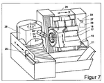
- a machine according to the invention is shown by way of example in FIG. 7. externally it corresponds to that described in the already mentioned DE 196 46 189 C2 CNC machine for producing bevel gears. She owns one Drive motor 16 for rotating the cutter head 7 about its axis of rotation 17. Motor 16 and cutter head 7 are located on a first carriage 18, the side of a machine housing 20 is guided and in height (parallel to the Z-axis) is movable. The machine housing 20 is in turn horizontally on a Machine bed 21 movable (parallel to the X-axis), on which also a second carriage 25 is located.
- This second carriage 25 carries one around a vertical Axis C rotatable workpiece carrier 28 with a workpiece spindle 30 and a Workpiece 31 which rotates in the workpiece carrier 28 about a horizontal axis 32 are stored.
- the second carriage 25 is also horizontally movable (parallel to the Y-axis), but perpendicular to the X-axis of the machine housing 20 and the Z-axis of the first carriage 18.
- these machine components form the mechanical conditions, spiral bevel gears by a rolling process in the To produce item procedure.
- the crucial difference of this inventive machine to a conventional machine consists in a changed control means 29 of the CNC control, in the cabinet 33rd is housed.
- a conventional control means ensures that, for example, after a rolling process in which the five axes X, Y, Z, C, and the workpiece axis 32 perform a previously calculated coupled motion must, the cutter head 7 and the workpiece 31 from their Wälzendpositionen be returned to their respective starting position.
- To the coupling of This returning is usually done by not losing five axes involved in the already described to Fig. 3 back rolling 6, after a Retracting the cutter head 7 from a tooth gap just generated 34th
- changed control means 29 of the CNC control can be cutter head 7 and workpiece 31 instead of the Reverse movement in each case a second starting position near the straight reached Wälzendpositionen lead, from where they after a partial operation a complete tooth gap 34 in a rolling process with reverse rolling direction to edit. In this way they also reach their original Starting positions, but not idle, but by a complete Operation.
- one additional control means provided in the conventional CNC control with the before and / or during each Wälzreaes a different influence the respective rolling direction on the accuracy of the bevel gear (workpiece) is compensable.
- This additional control means can be combined with the conventional CNC control form a modified control means 29.
- control means 29 differ from conventional ones Control means that they are capable of the inventive method so Execute that the rolling process takes place in a first direction and then a Rolling process is carried out in the opposite direction. In the rolling process in the one direction and the rolling process in the reverse direction come along different corrections of the setting parameters are used.
Landscapes
- Engineering & Computer Science (AREA)
- Mechanical Engineering (AREA)
- Gear Processing (AREA)
- Numerical Control (AREA)
- Milling Processes (AREA)
- Gear Transmission (AREA)
- Gears, Cams (AREA)
Applications Claiming Priority (2)
| Application Number | Priority Date | Filing Date | Title |
|---|---|---|---|
| DE10343854A DE10343854B4 (de) | 2003-09-23 | 2003-09-23 | Wälz-Verfahren für Spiralkegelräder |
| DE10343854 | 2003-09-23 |
Publications (2)
| Publication Number | Publication Date |
|---|---|
| EP1518630A1 true EP1518630A1 (fr) | 2005-03-30 |
| EP1518630B1 EP1518630B1 (fr) | 2011-10-05 |
Family
ID=34177888
Family Applications (1)
| Application Number | Title | Priority Date | Filing Date |
|---|---|---|---|
| EP04019896A Expired - Lifetime EP1518630B1 (fr) | 2003-09-23 | 2004-08-23 | Procédé et machine pour tailler par génération des roues coniques dentées en spirale |
Country Status (6)
| Country | Link |
|---|---|
| US (1) | US7156718B2 (fr) |
| EP (1) | EP1518630B1 (fr) |
| JP (1) | JP4664029B2 (fr) |
| AT (1) | ATE527077T1 (fr) |
| DE (1) | DE10343854B4 (fr) |
| ES (1) | ES2372601T3 (fr) |
Cited By (2)
| Publication number | Priority date | Publication date | Assignee | Title |
|---|---|---|---|---|
| EP3511100A1 (fr) * | 2018-01-15 | 2019-07-17 | Klingelnberg AG | Procédé destiné à tailler des pièces à usiner formant roue conique |
| EP2367656B2 (fr) † | 2008-12-19 | 2022-10-05 | Voith Patent GmbH | Machine-outil et procédé de fabrication de dentures |
Families Citing this family (16)
| Publication number | Priority date | Publication date | Assignee | Title |
|---|---|---|---|---|
| KR101320201B1 (ko) * | 2006-02-10 | 2013-10-23 | 클린게르베르크 게엠베하 | 완전 피치 에러 보정을 구비한 피칭 방법으로 베벨기어를 기계가공하는 방법 |
| US8087331B2 (en) * | 2009-02-06 | 2012-01-03 | GM Global Technology Operations LLC | Method of machining a carrier assembly |
| EP2314405B1 (fr) * | 2009-10-05 | 2012-12-26 | Klingelnberg AG | Procédé de production de roues coniques dotées d'une dentelure hypocycloïde dans le procédé de moulage en continu en utilisant des outils correspondants |
| DE102010023728A1 (de) * | 2010-06-14 | 2011-12-15 | Liebherr-Verzahntechnik Gmbh | Verfahren zum Herstellen einer Mehrzahl von identischen Zahnrädern mittles abspanender Bearbeitung |
| EP2647460B1 (fr) * | 2012-04-02 | 2014-12-10 | Klingelnberg AG | Procédé de fabrication de roues hypoïdes ou coniques par méthode d'immersion |
| CN102672281B (zh) * | 2012-06-07 | 2013-11-27 | 天津第一机床总厂 | 数控螺旋锥齿轮磨齿机 |
| US9481060B2 (en) * | 2013-02-05 | 2016-11-01 | Thomas Allen Mullis | Sharpening radial teeth on the surface of a disk |
| US9649707B2 (en) * | 2013-02-19 | 2017-05-16 | The Gleason Works | Slide rolling process for the generation of bevel gears |
| DE102015014313A1 (de) | 2015-11-05 | 2017-05-11 | Gleason-Pfauter Maschinenfabrik Gmbh | Verfahren zum Erzeugen oder Bearbeiten von Verzahnungen an Werkstücken |
| DE102016005257A1 (de) * | 2016-04-28 | 2017-11-02 | Liebherr-Verzahntechnik Gmbh | Verfahren zur Verzahnbearbeitung eines Werkstückes |
| WO2017201385A1 (fr) * | 2016-05-19 | 2017-11-23 | The Gleason Works | Chanfreinage de zone supérieure d'engrenages |
| EP3375555B1 (fr) * | 2017-03-17 | 2024-07-24 | Klingelnberg AG | Procédé de traitement des flancs de dent de pièces de roue dentée conique |
| FR3078643B1 (fr) * | 2018-03-12 | 2020-05-08 | Jtekt Europe | Procede d’usinage d’une denture a pas variable sur une cremaillere de direction |
| CN109551062B (zh) * | 2019-01-17 | 2021-02-02 | 常州市步云工控自动化股份有限公司 | 螺旋锥齿轮自动研磨的控制方法 |
| CN112676971A (zh) * | 2020-12-08 | 2021-04-20 | 安徽三山机械制造有限公司 | 一种伞齿轮的加工锻造工装 |
| CN120984994B (zh) * | 2025-10-21 | 2026-01-02 | 泰州里华齿轮制造有限公司 | 一种用于制造螺旋伞齿轮的角磨机 |
Citations (4)
| Publication number | Priority date | Publication date | Assignee | Title |
|---|---|---|---|---|
| GB1106149A (en) * | 1965-08-04 | 1968-03-13 | Gleason Works | Gear generating machine and method |
| DE2006752A1 (de) * | 1970-02-14 | 1971-09-02 | W Ferd Khngelnberg Sohne, 5630 Rem scheid | Verfahren zum Walz Schruppen von Kegel ntzeln mit epizyklischen Flankenhnien |
| US5310295A (en) * | 1993-03-22 | 1994-05-10 | The Gleason Works | Tool feeding method in gear manufacturing processes |
| DE19646189A1 (de) * | 1996-11-08 | 1998-05-14 | Klingelnberg Soehne Gmbh | Maschine zum Herstellen von bogenverzahnten Kegelrädern |
Family Cites Families (10)
| Publication number | Priority date | Publication date | Assignee | Title |
|---|---|---|---|---|
| US3583278A (en) * | 1968-10-21 | 1971-06-08 | Gleason Works | Methods of cutting bevel gears |
| CH556207A (de) * | 1973-03-26 | 1974-11-29 | Maag Zahnraeder & Maschinen Ag | Verfahren und maschine zur herstellung von schraegverzahnten evolventenstirnraedern mit innenverzahnung. |
| WO1989001838A1 (fr) * | 1987-08-24 | 1989-03-09 | The Gleason Works | Machine a tailler des dents biseautees et des engrenages hypoides |
| DE4012432C1 (fr) * | 1990-04-19 | 1991-07-04 | Hermann Pfauter Gmbh & Co, 7140 Ludwigsburg, De | |
| JP2588353B2 (ja) * | 1993-01-26 | 1997-03-05 | 豊精密工業株式会社 | 歯車加工装置 |
| JPH06339811A (ja) * | 1993-05-31 | 1994-12-13 | Nissan Motor Co Ltd | 歯車の歯先への面取部の形成方法 |
| DE19517360C1 (de) * | 1995-05-11 | 1996-05-23 | Klingelnberg Soehne | Verfahren zum Schleifen der Verzahnung von bogenverzahnten Kegelrädern |
| US6050883A (en) * | 1996-05-10 | 2000-04-18 | Klingelnberg Sohne Gmbh | Method of grinding the teeth of spiral-toothed bevel gear wheels |
| US5716174A (en) * | 1996-08-29 | 1998-02-10 | The Gleason Works | Tool feeding method |
| JP2003251527A (ja) * | 2002-02-27 | 2003-09-09 | Toyota Motor Corp | 曲歯傘歯車の歯形成形装置と歯形成形方法 |
-
2003
- 2003-09-23 DE DE10343854A patent/DE10343854B4/de not_active Expired - Fee Related
-
2004
- 2004-05-03 US US10/837,949 patent/US7156718B2/en not_active Expired - Lifetime
- 2004-08-23 AT AT04019896T patent/ATE527077T1/de active
- 2004-08-23 ES ES04019896T patent/ES2372601T3/es not_active Expired - Lifetime
- 2004-08-23 EP EP04019896A patent/EP1518630B1/fr not_active Expired - Lifetime
- 2004-09-21 JP JP2004273520A patent/JP4664029B2/ja not_active Expired - Fee Related
Patent Citations (4)
| Publication number | Priority date | Publication date | Assignee | Title |
|---|---|---|---|---|
| GB1106149A (en) * | 1965-08-04 | 1968-03-13 | Gleason Works | Gear generating machine and method |
| DE2006752A1 (de) * | 1970-02-14 | 1971-09-02 | W Ferd Khngelnberg Sohne, 5630 Rem scheid | Verfahren zum Walz Schruppen von Kegel ntzeln mit epizyklischen Flankenhnien |
| US5310295A (en) * | 1993-03-22 | 1994-05-10 | The Gleason Works | Tool feeding method in gear manufacturing processes |
| DE19646189A1 (de) * | 1996-11-08 | 1998-05-14 | Klingelnberg Soehne Gmbh | Maschine zum Herstellen von bogenverzahnten Kegelrädern |
Cited By (3)
| Publication number | Priority date | Publication date | Assignee | Title |
|---|---|---|---|---|
| EP2367656B2 (fr) † | 2008-12-19 | 2022-10-05 | Voith Patent GmbH | Machine-outil et procédé de fabrication de dentures |
| EP3511100A1 (fr) * | 2018-01-15 | 2019-07-17 | Klingelnberg AG | Procédé destiné à tailler des pièces à usiner formant roue conique |
| US10857607B2 (en) | 2018-01-15 | 2020-12-08 | Klingelnberg Ag | Method for gear cutting of bevel gear workpieces |
Also Published As
| Publication number | Publication date |
|---|---|
| JP4664029B2 (ja) | 2011-04-06 |
| ATE527077T1 (de) | 2011-10-15 |
| US7156718B2 (en) | 2007-01-02 |
| DE10343854B4 (de) | 2005-12-29 |
| ES2372601T3 (es) | 2012-01-24 |
| EP1518630B1 (fr) | 2011-10-05 |
| DE10343854A1 (de) | 2005-05-12 |
| JP2005096070A (ja) | 2005-04-14 |
| US20050064794A1 (en) | 2005-03-24 |
Similar Documents
| Publication | Publication Date | Title |
|---|---|---|
| EP1518630B1 (fr) | Procédé et machine pour tailler par génération des roues coniques dentées en spirale | |
| EP1981674B1 (fr) | Procede d'usinage de roues coniques dans un procede de division avec compensation complete des erreurs de division | |
| DE69712607T2 (de) | Verfahren zum bearbeiten von zahnrädern während des teilens | |
| EP2385885B2 (fr) | Dispositif et procédé pour tailler des dents dans des pièces | |
| DE69417882T2 (de) | Werkzeugeinstechverfahren für zahnradherstellverfahren | |
| DE4122460C1 (fr) | ||
| EP3412395B1 (fr) | Dispositifs et procédé de chanfreinage d'une pièce à denture intérieure | |
| EP3388179A1 (fr) | Procédé d'usinage de denture d'une pièce à usiner | |
| DE3752340T2 (de) | Mehrfachachsenzahnradwälzmaschine zur Herstellung von Kegelrädern und Hypoidrädern | |
| DE102008037514A1 (de) | Wälzschälvorrichtung und -verfahren | |
| EP2367656A1 (fr) | Machine-outil et procédé de fabrication de dentures | |
| EP3412393B1 (fr) | Dispositifs et procédé de chanfreinage d'une pièce à denture intérieure | |
| DD237998A5 (de) | Verfahren und vorrichtung zur herstellung evolventenfoermiger zahnflanken | |
| DE102011118312A1 (de) | Verfahren und Vorrichtung zur Bearbeitung von Zahnkanten | |
| WO2016091356A1 (fr) | Procédé de traitement d'une denture, ensemble d'outil et machine à denture | |
| DE2604281B2 (de) | Maschine zum Schaben oder Rollen der Zahnflanken von drehbar in ihr gelagerten Zahnrädern | |
| EP2961552B1 (fr) | Procédé de fabrication ou d'usinage par enlèvement de matière d'une denture, et machine de taillage d'engrenages | |
| DE805344C (de) | Nach dem Abwaelzverfahren arbeitende Verzahnungsmaschine | |
| DE3734828C1 (de) | Verfahren zum Teilwaelzschleifen von Zahnraedern sowie eine dafuer geeignete Maschine | |
| DE10230148B4 (de) | Verfahren zum Bearbeiten von mittels Wälzfräsen hergestellten Zahnrädern | |
| DE69426111T2 (de) | Verfahren und Maschine zum Herstellen von Kronenrädern | |
| EP0522448B1 (fr) | Procédé et dispositif pour l'usinage des arêtes de dents d'une roue dentée | |
| DE102017009924B4 (de) | Verfahren zur Bearbeitung von Kegelrad-Werkstücken | |
| EP3511100B1 (fr) | Procédé destiné à tailler des pièces à usiner formant roue conique | |
| EP3287222A1 (fr) | Procédé d'usinage de dentures de pièces d'usinage d'accouplement plan selon un procédé de pièces semi-complètes |
Legal Events
| Date | Code | Title | Description |
|---|---|---|---|
| PUAI | Public reference made under article 153(3) epc to a published international application that has entered the european phase |
Free format text: ORIGINAL CODE: 0009012 |
|
| AK | Designated contracting states |
Kind code of ref document: A1 Designated state(s): AT BE BG CH CY CZ DE DK EE ES FI FR GB GR HU IE IT LI LU MC NL PL PT RO SE SI SK TR |
|
| AX | Request for extension of the european patent |
Extension state: AL HR LT LV MK |
|
| 17P | Request for examination filed |
Effective date: 20050506 |
|
| AKX | Designation fees paid |
Designated state(s): AT DE ES GB IT SE |
|
| 17Q | First examination report despatched |
Effective date: 20080605 |
|
| GRAJ | Information related to disapproval of communication of intention to grant by the applicant or resumption of examination proceedings by the epo deleted |
Free format text: ORIGINAL CODE: EPIDOSDIGR1 |
|
| GRAP | Despatch of communication of intention to grant a patent |
Free format text: ORIGINAL CODE: EPIDOSNIGR1 |
|
| GRAS | Grant fee paid |
Free format text: ORIGINAL CODE: EPIDOSNIGR3 |
|
| GRAA | (expected) grant |
Free format text: ORIGINAL CODE: 0009210 |
|
| RIN1 | Information on inventor provided before grant (corrected) |
Inventor name: RIBBECK, KARL-MARTIN Inventor name: BLASBERG, HERBERT Inventor name: RADERMACHER, MATTHIAS Inventor name: KOENIG, TORSTEN |
|
| AK | Designated contracting states |
Kind code of ref document: B1 Designated state(s): AT DE ES GB IT SE |
|
| REG | Reference to a national code |
Ref country code: GB Ref legal event code: FG4D Free format text: NOT ENGLISH |
|
| REG | Reference to a national code |
Ref country code: DE Ref legal event code: R096 Ref document number: 502004012921 Country of ref document: DE Effective date: 20111229 |
|
| REG | Reference to a national code |
Ref country code: ES Ref legal event code: FG2A Ref document number: 2372601 Country of ref document: ES Kind code of ref document: T3 Effective date: 20120124 Ref country code: SE Ref legal event code: TRGR |
|
| PLBE | No opposition filed within time limit |
Free format text: ORIGINAL CODE: 0009261 |
|
| STAA | Information on the status of an ep patent application or granted ep patent |
Free format text: STATUS: NO OPPOSITION FILED WITHIN TIME LIMIT |
|
| 26N | No opposition filed |
Effective date: 20120706 |
|
| REG | Reference to a national code |
Ref country code: DE Ref legal event code: R097 Ref document number: 502004012921 Country of ref document: DE Effective date: 20120706 |
|
| PGFP | Annual fee paid to national office [announced via postgrant information from national office to epo] |
Ref country code: DE Payment date: 20190822 Year of fee payment: 16 Ref country code: IT Payment date: 20190829 Year of fee payment: 16 Ref country code: ES Payment date: 20190923 Year of fee payment: 16 Ref country code: SE Payment date: 20190821 Year of fee payment: 16 |
|
| PGFP | Annual fee paid to national office [announced via postgrant information from national office to epo] |
Ref country code: AT Payment date: 20190822 Year of fee payment: 16 Ref country code: GB Payment date: 20190821 Year of fee payment: 16 |
|
| REG | Reference to a national code |
Ref country code: DE Ref legal event code: R119 Ref document number: 502004012921 Country of ref document: DE |
|
| REG | Reference to a national code |
Ref country code: SE Ref legal event code: EUG |
|
| REG | Reference to a national code |
Ref country code: AT Ref legal event code: MM01 Ref document number: 527077 Country of ref document: AT Kind code of ref document: T Effective date: 20200823 |
|
| GBPC | Gb: european patent ceased through non-payment of renewal fee |
Effective date: 20200823 |
|
| PG25 | Lapsed in a contracting state [announced via postgrant information from national office to epo] |
Ref country code: AT Free format text: LAPSE BECAUSE OF NON-PAYMENT OF DUE FEES Effective date: 20200823 Ref country code: SE Free format text: LAPSE BECAUSE OF NON-PAYMENT OF DUE FEES Effective date: 20200824 |
|
| PG25 | Lapsed in a contracting state [announced via postgrant information from national office to epo] |
Ref country code: DE Free format text: LAPSE BECAUSE OF NON-PAYMENT OF DUE FEES Effective date: 20210302 Ref country code: IT Free format text: LAPSE BECAUSE OF NON-PAYMENT OF DUE FEES Effective date: 20200823 |
|
| PG25 | Lapsed in a contracting state [announced via postgrant information from national office to epo] |
Ref country code: GB Free format text: LAPSE BECAUSE OF NON-PAYMENT OF DUE FEES Effective date: 20200823 |
|
| REG | Reference to a national code |
Ref country code: ES Ref legal event code: FD2A Effective date: 20220103 |
|
| PG25 | Lapsed in a contracting state [announced via postgrant information from national office to epo] |
Ref country code: ES Free format text: LAPSE BECAUSE OF NON-PAYMENT OF DUE FEES Effective date: 20200824 |