EP1518749A2 - Dispositif pour contrôler le volume de fluide lors du réglage de forme de sièges - Google Patents
Dispositif pour contrôler le volume de fluide lors du réglage de forme de sièges Download PDFInfo
- Publication number
- EP1518749A2 EP1518749A2 EP20040019352 EP04019352A EP1518749A2 EP 1518749 A2 EP1518749 A2 EP 1518749A2 EP 20040019352 EP20040019352 EP 20040019352 EP 04019352 A EP04019352 A EP 04019352A EP 1518749 A2 EP1518749 A2 EP 1518749A2
- Authority
- EP
- European Patent Office
- Prior art keywords
- fluid
- connection openings
- housing
- slide
- openings
- Prior art date
- Legal status (The legal status is an assumption and is not a legal conclusion. Google has not performed a legal analysis and makes no representation as to the accuracy of the status listed.)
- Granted
Links
- 239000012530 fluid Substances 0.000 title claims abstract description 32
- 238000006073 displacement reaction Methods 0.000 claims 1
- 238000013022 venting Methods 0.000 abstract description 4
- 238000007789 sealing Methods 0.000 description 2
- 230000015572 biosynthetic process Effects 0.000 description 1
- 238000004891 communication Methods 0.000 description 1
- 238000010276 construction Methods 0.000 description 1
- 238000011161 development Methods 0.000 description 1
- 230000018109 developmental process Effects 0.000 description 1
- 230000000694 effects Effects 0.000 description 1
- 239000007789 gas Substances 0.000 description 1
- 239000007788 liquid Substances 0.000 description 1
- 238000000034 method Methods 0.000 description 1
- 238000007493 shaping process Methods 0.000 description 1
- 230000002123 temporal effect Effects 0.000 description 1
- 238000012549 training Methods 0.000 description 1
Images

Classifications
-
- F—MECHANICAL ENGINEERING; LIGHTING; HEATING; WEAPONS; BLASTING
- F16—ENGINEERING ELEMENTS AND UNITS; GENERAL MEASURES FOR PRODUCING AND MAINTAINING EFFECTIVE FUNCTIONING OF MACHINES OR INSTALLATIONS; THERMAL INSULATION IN GENERAL
- F16K—VALVES; TAPS; COCKS; ACTUATING-FLOATS; DEVICES FOR VENTING OR AERATING
- F16K11/00—Multiple-way valves, e.g. mixing valves; Pipe fittings incorporating such valves
- F16K11/02—Multiple-way valves, e.g. mixing valves; Pipe fittings incorporating such valves with all movable sealing faces moving as one unit
- F16K11/06—Multiple-way valves, e.g. mixing valves; Pipe fittings incorporating such valves with all movable sealing faces moving as one unit comprising only sliding valves, i.e. sliding closure elements
- F16K11/065—Multiple-way valves, e.g. mixing valves; Pipe fittings incorporating such valves with all movable sealing faces moving as one unit comprising only sliding valves, i.e. sliding closure elements with linearly sliding closure members
- F16K11/07—Multiple-way valves, e.g. mixing valves; Pipe fittings incorporating such valves with all movable sealing faces moving as one unit comprising only sliding valves, i.e. sliding closure elements with linearly sliding closure members with cylindrical slides
- F16K11/0716—Multiple-way valves, e.g. mixing valves; Pipe fittings incorporating such valves with all movable sealing faces moving as one unit comprising only sliding valves, i.e. sliding closure elements with linearly sliding closure members with cylindrical slides with fluid passages through the valve member
-
- B—PERFORMING OPERATIONS; TRANSPORTING
- B60—VEHICLES IN GENERAL
- B60N—SEATS SPECIALLY ADAPTED FOR VEHICLES; VEHICLE PASSENGER ACCOMMODATION NOT OTHERWISE PROVIDED FOR
- B60N2/00—Seats specially adapted for vehicles; Arrangement or mounting of seats in vehicles
- B60N2/90—Details or parts not otherwise provided for
- B60N2/914—Hydro-pneumatic adjustments of the shape
-
- Y—GENERAL TAGGING OF NEW TECHNOLOGICAL DEVELOPMENTS; GENERAL TAGGING OF CROSS-SECTIONAL TECHNOLOGIES SPANNING OVER SEVERAL SECTIONS OF THE IPC; TECHNICAL SUBJECTS COVERED BY FORMER USPC CROSS-REFERENCE ART COLLECTIONS [XRACs] AND DIGESTS
- Y10—TECHNICAL SUBJECTS COVERED BY FORMER USPC
- Y10T—TECHNICAL SUBJECTS COVERED BY FORMER US CLASSIFICATION
- Y10T137/00—Fluid handling
- Y10T137/8593—Systems
- Y10T137/86493—Multi-way valve unit
- Y10T137/86501—Sequential distributor or collector type
-
- Y—GENERAL TAGGING OF NEW TECHNOLOGICAL DEVELOPMENTS; GENERAL TAGGING OF CROSS-SECTIONAL TECHNOLOGIES SPANNING OVER SEVERAL SECTIONS OF THE IPC; TECHNICAL SUBJECTS COVERED BY FORMER USPC CROSS-REFERENCE ART COLLECTIONS [XRACs] AND DIGESTS
- Y10—TECHNICAL SUBJECTS COVERED BY FORMER USPC
- Y10T—TECHNICAL SUBJECTS COVERED BY FORMER US CLASSIFICATION
- Y10T137/00—Fluid handling
- Y10T137/8593—Systems
- Y10T137/86493—Multi-way valve unit
- Y10T137/86574—Supply and exhaust
- Y10T137/8667—Reciprocating valve
Definitions
- the invention relates to a device for controlling the volume of fluid in Forming elements of seats, in particular vehicle seats, according to the Preamble of claim 1.
- Such deformation elements in seats serve the Improvement of seating comfort through individual adjustment of seat contours the seat to the seat occupant and are in so-called.
- Multikonturlehnen in Vehicle seats also used for massage of the seat occupant.
- a known vehicle seat (DE 100 63 478 A1) are more than Air cushion running form changing elements of a control device via a pneumatic control element actuated offset in time and lead to Massage a person using the seat a Vorhub by filling with Compressed air and a return stroke by venting off.
- the filling and venting the air cushion by means of electromagnetic valves, the air cushion to Cushion groups are grouped together and in each one from a compressed air source a cushion group leading compressed air line, the series connection of a 3/2-way solenoid valve and a 2/2 way solenoid valve.
- the valves are assembled to form manifolds.
- Such valve blocks are heavy and bulky and relative to the seat itself difficult to integrate.
- a known device of this type (DE 31 42 833 A1) has the Slide valve as a spool on a rotary valve, which has a central Pressure space containing the medium from a pressure modulator is supplied.
- This rotary valve is approximately cup-shaped and contains in the Sidewall a radial, outwardly open channel. In this area sits on the outer surface of the wall of the rotary valve with a sealing ring central passage, which is aligned with the channel of the rotary valve.
- the Rotary valve is rotatable within an approximately pot-shaped housing.
- the pot-shaped housing has circumferentially spaced inner radial Channels that merge into axial channels with connection openings for cables.
- the inner channels are located axially at the level of the one radial channel of the Rotary valve.
- the rotary valve can in three different rotational positions be rotated, in which case each of its channel via the passage in the Sealing ring comes into contact with an inner channel of the housing, so that Fluid in the central pressure chamber via this channel connection in the respective line can get to the respective shape change element. Also
- a pressure modulator to a structural unit united, builds big and heavy and needs a lot of space.
- the invention has for its object to provide a device for controlling the Specify fluid volume of the aforementioned type, the same Functionality has a smaller volume and construction weight.
- the inventive device for controlling the fluid volume in Form change elements of seats has the advantage that through the training the control member as a slide valve with a control slide in the form of an axial slide, the at least one acted upon with fluid control port with each brings one of the connection openings in fluid communication, to simple Way any control of the individual strain elements can be realized.
- the slide valve can be at the same Functionality smaller and lighter perform and constructive advantageous to integrate into the seat.
- the slide valve can be multi-parallel Control openings are executed, each having a control opening of a assigned to a specific number of connection openings. By providing an additional switching valve, it is possible a plurality of Shaping elements in the seat simultaneously or sequentially with fluid to fill or empty.
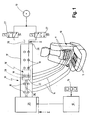
- the vehicle seat 10 shown in Fig. 1 for example, in the Backrest four formed as air cushion shape changing elements 11 and in the seat, for example, two also designed as air cushions Form change elements 11 integrated.
- the fluid volume in the Form change elements 11 so the air filling of the air cushion, modified on the one hand, the seat contour to the individual wishes of the Seat occupant or otherwise a massage of the seat occupant perform.
- Under fluid is understood here any flowing medium, ie In addition to air or other gases and liquids. Usually, though preferably compressed air used.
- the Forming elements 11, here air cushion in a fixed, temporal Drain by filling (inflation) a forward stroke and by draining (venting) a return stroke.
- the sequence program is in a microcomputer 12 stored and can be accessed via a keyboard 15 of the seat user become.
- the microcomputer 12 controls a control member which is connected between a Fluid pressure source 13 and the leads 14 to the deformation elements 11th is arranged.
- the fluid pressure source 13 is an air pressure source, e.g. a compressor with Compressed air reservoir
- the control member is a pneumatic control member.
- the control member is designed as a slide valve 16. It comprises a housing 17 with connection openings 18 for each one supply line 14 to one of Form change elements 11 and one adjustable in the housing 17 Spool 19.
- the spool 19 has at least one with the Connection openings 18 in the housing 17 cooperating control opening 20th and at least one opening in the control port 20 connecting channel 21st on, which can be acted upon with fluid from the fluid pressure source 13.
- the control port 20 with a selected Connection opening 18 are aligned so that a connection between the fluid pressure source 13 and the to a deformation element 11th leading supply line 14 is made.
- connection openings 18 in Housing 17 is opened, and thus the connected deformation elements 11 emptied, while in the embodiment of FIGS. 3 and 4, the remaining Connection openings 18 closed by the spool 19 fluid-tight are so that the fluid or air pressure in the deformation elements 11th is held.
- the spool 19 as Axial slide 22 is formed. It includes a control port 20 and the Connecting channel 21 containing slide head 23 and one with the slide head 23 rigidly connected slide rod 24.
- the slide rod 24 is provided with a motor drive 25, e.g. a linear stepper motor, coupled.
- the one in the elongate, rectangular housing 17 axially displaceable slide head 23 is in the area of the control opening 20 by means of a surrounding this Ring seal 28 with respect to the connection openings 18 containing Housing wall 171 sealed.
- the connection openings 18 are in Sliding direction of the slide head 23 lined up at a distance one behind the other. in the Embodiment of FIGS.
- connection openings 18 in two Groups with equal number of connection openings 18 divided. In every Group are the connection openings 18 in the sliding direction of the slide head 23 arranged one behind the other, wherein the two formed by the two groups Rows are aligned parallel to each other.
- the pusher head 23 has two separate control ports 20 with connection channel 21, of which in each case one Control port 20 of a row of the connection openings 18 is assigned.
- Everyone Connection channel 21 is connected via a separate connecting line 26 with the Fluid pressure source 13 connected.
- each connecting line 26 is a 3/2-way solenoid valve 27 arranged over which the associated connection channel 21st connected to the fluid pressure source 13 or to a discharge line connected, so can be vented.
Landscapes
- Engineering & Computer Science (AREA)
- Mechanical Engineering (AREA)
- General Engineering & Computer Science (AREA)
- Aviation & Aerospace Engineering (AREA)
- Transportation (AREA)
- Seats For Vehicles (AREA)
- Multiple-Way Valves (AREA)
- Massaging Devices (AREA)
- Chair Legs, Seat Parts, And Backrests (AREA)
- Mattresses And Other Support Structures For Chairs And Beds (AREA)
Applications Claiming Priority (2)
| Application Number | Priority Date | Filing Date | Title |
|---|---|---|---|
| DE2003144974 DE10344974B3 (de) | 2003-09-27 | 2003-09-27 | Vorrichtung zur Steuerung des Fluidvolumens in Formänderungselementen von Sitzen |
| DE10344974 | 2003-09-27 |
Publications (3)
| Publication Number | Publication Date |
|---|---|
| EP1518749A2 true EP1518749A2 (fr) | 2005-03-30 |
| EP1518749A3 EP1518749A3 (fr) | 2007-05-02 |
| EP1518749B1 EP1518749B1 (fr) | 2008-06-18 |
Family
ID=34042284
Family Applications (1)
| Application Number | Title | Priority Date | Filing Date |
|---|---|---|---|
| EP20040019352 Expired - Lifetime EP1518749B1 (fr) | 2003-09-27 | 2004-08-14 | Dispositif pour contrôler le volume de fluide lors du réglage de forme de sièges |
Country Status (4)
| Country | Link |
|---|---|
| US (1) | US7267404B2 (fr) |
| EP (1) | EP1518749B1 (fr) |
| JP (1) | JP2005103261A (fr) |
| DE (2) | DE10344974B3 (fr) |
Families Citing this family (36)
| Publication number | Priority date | Publication date | Assignee | Title |
|---|---|---|---|---|
| DE602004024276D1 (de) * | 2003-10-21 | 2010-01-07 | Ts Tech Co Ltd | Fahrzeugsitz mit System zum Ermöglichen von Abbau der Müdigkeit von der im Sitz sitzenden Person |
| US7681593B1 (en) * | 2004-12-13 | 2010-03-23 | Horvat Branimir L | Sequential distributor of gases and liquids |
| DE102006012377B4 (de) * | 2006-03-17 | 2021-09-23 | Bayerische Motoren Werke Aktiengesellschaft | Konturverstellbarer Fahrzeugsitz mit einer Rückenlehne |
| DE102006015523A1 (de) * | 2006-03-31 | 2007-10-04 | Recaro Aircraft Seating Gmbh & Co. Kg | Sitzvorrichtung |
| DE102008015763B4 (de) | 2007-07-02 | 2018-08-02 | Conti Temic Microelectronic Gmbh | Vorrichtung zur Be-/Entlüftung einer Mehrzahl von pneumatischen Aktuatoren, Sitz und Fahrzeug mit einer derartigen Vorrichtung |
| US8162398B2 (en) * | 2009-03-26 | 2012-04-24 | Schukra of North America Co. | Zone lumbar massage system |
| EP2361800B1 (fr) * | 2010-02-17 | 2013-04-24 | L & P Swiss Holding AG | Dispositif d'ajustement pour siège et procédé de fonctionnement d'un dispositif d'ajustement |
| DE102011107677B4 (de) * | 2011-07-13 | 2013-12-05 | Faurecia Autositze Gmbh | Fahrzeugsitz |
| WO2013170335A1 (fr) * | 2012-05-16 | 2013-11-21 | Schukra of North America Co. | Système et procédé pour fonction de transfert de linéarisation de signal de pression |
| US9086189B2 (en) | 2012-05-16 | 2015-07-21 | Leggett & Platt Canada Co. | System and method for a pressure signal linearization transfer function |
| DE102012209449A1 (de) * | 2012-06-05 | 2013-12-05 | Conti Temic Microelectronic Gmbh | Verfahren und Vorrichtung zum Befüllen und Entleeren eines Sitzkissens |
| DE102012212686B4 (de) * | 2012-07-19 | 2016-11-10 | Alfmeier Präzision AG Baugruppen und Systemlösungen | Ventil |
| DE102012224449A1 (de) * | 2012-12-27 | 2014-07-03 | Robert Bosch Gmbh | Sitzvorrichtung |
| EP2769878B1 (fr) * | 2013-02-20 | 2015-03-25 | Schukra Gerätebau GmbH | Dispositif de réglage d'un siège et procédé de fourniture de réglage de siège |
| US9097365B2 (en) * | 2013-03-15 | 2015-08-04 | Alps Electric Co., Ltd. | Micro-valve assembly |
| DE102013220563A1 (de) * | 2013-10-11 | 2015-04-16 | Conti Temic Microelectronic Gmbh | Vorrichtung zum pneumatischen Befüllen und Entleeren von Blasen in einem Sitz eines Verkehrsmittels |
| US10328823B2 (en) | 2014-06-09 | 2019-06-25 | Lear Corporation | Adjustable seat assembly |
| US9987961B2 (en) | 2014-06-09 | 2018-06-05 | Lear Corporation | Adjustable seat assembly |
| JP6462906B2 (ja) * | 2015-03-12 | 2019-01-30 | 恵州市唐群座椅科技股▲ふん▼有限公司Tangtring Seating Technology Inc. | 座席のランバーサポートの段階的調節システム |
| DE102015113029B4 (de) * | 2015-04-09 | 2022-05-25 | Alfmeier Präzision AG Baugruppen und Systemlösungen | Vorrichtung und Verfahren zur Einstellung einer Kontur eines Fahrzeugsitzes mit Konturverstellung |
| US9884570B2 (en) | 2015-05-19 | 2018-02-06 | Lear Corporation | Adjustable seat assembly |
| US9845026B2 (en) | 2015-05-19 | 2017-12-19 | Lear Corporation | Adjustable seat assembly |
| DE112016003128B4 (de) * | 2015-07-10 | 2024-05-29 | Lear Corporation | Fahrzeugsitzaufbau und Lordosenstützsystem für einen Fahrzeugsitzaufbau |
| US9661928B2 (en) | 2015-09-29 | 2017-05-30 | Lear Corporation | Air bladder assembly for seat bottoms of seat assemblies |
| DE102015219197B4 (de) | 2015-10-05 | 2019-07-04 | Conti Temic Microelectronic Gmbh | Pneumatisches Magnetventil |
| US9827888B2 (en) | 2016-01-04 | 2017-11-28 | Lear Corporation | Seat assemblies with adjustable side bolster actuators |
| DE102016209872A1 (de) | 2016-06-06 | 2017-12-07 | Continental Automotive Gmbh | Fahrzeugbordnetz mit Wechselrichter, Energiespeicher, elektrischer Maschine und Wechselstrom-Übertragungsanschluss |
| DE102016212586A1 (de) * | 2016-07-11 | 2018-01-11 | Conti Temic Microelectronic Gmbh | Pneumatische Vorrichtung |
| DE102016214529B4 (de) * | 2016-08-05 | 2023-06-07 | Conti Temic Microelectronic Gmbh | Verfahren zur Herstellung einer mit Druckmittel befüllbaren Blase als Stellelement für einen Sitz |
| US10363852B2 (en) | 2016-09-15 | 2019-07-30 | Ford Global Technologies, Llc | Apparatus and method for customizing a vehicle seat |
| US10286815B2 (en) * | 2017-04-03 | 2019-05-14 | Ford Global Technologies, Llc | H-point lift options for sleeper seats |
| US20180345823A1 (en) | 2017-06-01 | 2018-12-06 | Lear Corporation | Seat assembly adjustment patterns |
| US10525854B2 (en) * | 2018-01-02 | 2020-01-07 | Dowco, Inc. | Adjustable seat |
| CN222426612U (zh) * | 2024-02-06 | 2025-02-07 | 科际精密股份有限公司 | 脉动控制装置 |
| KR20250156963A (ko) * | 2024-04-26 | 2025-11-04 | 현대트랜시스 주식회사 | 차량 시트용 공압 제어기 |
| CN120557274B (zh) * | 2025-07-05 | 2025-11-18 | 广东安昂智能制造供应链技术有限公司 | 一种直线轴承滑动机构 |
Citations (2)
| Publication number | Priority date | Publication date | Assignee | Title |
|---|---|---|---|---|
| DE3142833A1 (de) | 1981-10-29 | 1983-05-11 | Daimler-Benz Ag, 7000 Stuttgart | Einrichtung zur druckbeaufschlagung mehrerer ansteuerbarer elemente |
| DE10063478A1 (de) | 2000-12-20 | 2002-07-04 | Alfmeier Praez Ag | Sitz, insbesondere Fahrzeugsitz |
Family Cites Families (12)
| Publication number | Priority date | Publication date | Assignee | Title |
|---|---|---|---|---|
| GB1410398A (en) * | 1973-09-29 | 1975-10-15 | Martonair Ltd | Slide valve |
| US4136853A (en) * | 1975-02-24 | 1979-01-30 | Atlas Copco Aktiebolag | Slide valve |
| US4000685A (en) * | 1975-05-05 | 1977-01-04 | Montalvo Jr Edwin J | Push/pull valve for two or three way operation |
| JPS57136413A (en) * | 1981-02-19 | 1982-08-23 | Aisin Seiki | Air supply and discharge system of air lumber support |
| US4491157A (en) * | 1981-03-06 | 1985-01-01 | Aisin Seiki Kabushiki Kaisha | Valve assembly for air bag control |
| JPS58160679A (ja) * | 1982-03-18 | 1983-09-24 | Aisin Seiki Co Ltd | エアランバ−サポ−トバルブ |
| GB8326702D0 (en) * | 1983-10-06 | 1983-11-09 | Brisland M J | Slide valve |
| DE8334946U1 (de) * | 1983-12-06 | 1984-04-05 | Hauke, Günther, Dipl.-Ing. (FH) | Steuervorrichtung fuer pneumatische systeme mit mindestens zwei aufblasbaren luftkammern in sitzen oder liegen |
| US5135282A (en) * | 1989-08-18 | 1992-08-04 | Man Nutzfahrzeuge Aktiengesellschaft | Motor vehicle seat back |
| US6203105B1 (en) * | 1999-08-20 | 2001-03-20 | Mccord Winn Textron Inc. | Vehicle impact responsive multiple bladder seating and headrest system and method |
| EP1352189B1 (fr) * | 2001-01-18 | 2008-06-04 | Roho, Inc. | Soupape pour coussin cellulaire compartimente |
| US6895988B2 (en) * | 2002-09-10 | 2005-05-24 | Grant Airmass Corporation | Self-actuating control valve for a bed pad or seat pad |
-
2003
- 2003-09-27 DE DE2003144974 patent/DE10344974B3/de not_active Expired - Fee Related
-
2004
- 2004-08-14 EP EP20040019352 patent/EP1518749B1/fr not_active Expired - Lifetime
- 2004-08-14 DE DE200450007380 patent/DE502004007380D1/de not_active Expired - Lifetime
- 2004-09-22 US US10/947,462 patent/US7267404B2/en not_active Expired - Lifetime
- 2004-09-22 JP JP2004274903A patent/JP2005103261A/ja active Pending
Patent Citations (2)
| Publication number | Priority date | Publication date | Assignee | Title |
|---|---|---|---|---|
| DE3142833A1 (de) | 1981-10-29 | 1983-05-11 | Daimler-Benz Ag, 7000 Stuttgart | Einrichtung zur druckbeaufschlagung mehrerer ansteuerbarer elemente |
| DE10063478A1 (de) | 2000-12-20 | 2002-07-04 | Alfmeier Praez Ag | Sitz, insbesondere Fahrzeugsitz |
Also Published As
| Publication number | Publication date |
|---|---|
| US20050067868A1 (en) | 2005-03-31 |
| DE10344974B3 (de) | 2005-02-10 |
| DE502004007380D1 (de) | 2008-07-31 |
| EP1518749B1 (fr) | 2008-06-18 |
| EP1518749A3 (fr) | 2007-05-02 |
| JP2005103261A (ja) | 2005-04-21 |
| US7267404B2 (en) | 2007-09-11 |
Similar Documents
| Publication | Publication Date | Title |
|---|---|---|
| EP1518749B1 (fr) | Dispositif pour contrôler le volume de fluide lors du réglage de forme de sièges | |
| DE60125369T2 (de) | Verfahren und station zum wechseln von flüssigkeit für eine spritzanlage | |
| EP1544155B1 (fr) | Tête de remplissage et machine de remplissage avec de telles têtes de remplissage | |
| DE2555156B2 (de) | Hochdruck-Mischkopf | |
| DE2607641B2 (de) | Hochdruck-Mischkopf | |
| CH658109A5 (de) | 5/2-wegeventil in schieberbauart fuer die druckmittelversorgung eines servomotors. | |
| DE4324939C2 (de) | Kolbenschieberventil | |
| DE19728607A9 (de) | Formvorrichtung mit mehrfachentgasung | |
| EP0224774B1 (fr) | Distributeur progressif pour lubrifiant | |
| DE19534660C1 (de) | Konturverstellbarer Sitz | |
| DE10152561A1 (de) | Rückenlehne für einen Sitz | |
| DE1281281B (de) | Hoehenregelvorrichtung mit Niveauvorwaehlung fuer Fahrzeuge | |
| DE1528541C3 (de) | Geschwindigkeitssteuereinrichtung für einen Hydraulikmotor | |
| DE2543227C3 (de) | Brühbehälter für eine Maschine | |
| DE2615761C3 (de) | Einrichtung zum Einbringen von staubförmigem Brennstoff in die Zylinder einer Brennkraftmaschine | |
| EP1361036A1 (fr) | Apparail pour l'emboutissage thermoformique, le poinçon avec valve integrée | |
| DE10220701A1 (de) | Formwerkzeug zum Tiefziehen von Behältern aus thermoplastischem Kunststoff | |
| DE20302825U1 (de) | Druck- und Durchfluß-Regulierventil für Druckluftwerkzeuge | |
| DE10257117B4 (de) | Ventilsystem zum Befüllen und Entlüften von Sitzpolstern, insbesondere in Fahrzeugen | |
| EP0640429B1 (fr) | Entraînement pneumatique en particulier pour l'actionnement d'électrodes de soudage | |
| DE69606589T2 (de) | Druckbehälterventil sowie mit einem solchen Ventil versehener Druckbehälter | |
| DE3326793C2 (de) | Schieberventil mit zwei in der zylindrischen Bohrung eines Ventilgehäuses axial versetzt gegeneinander angeordneten Kolben | |
| DE1601734A1 (de) | Vorrichtung zur Steuerung der Bewegung eines Hauptkolbens in einem hydraulischen Motor | |
| DE69725241T2 (de) | Verfahren und Vorrichtung zum Verteilen einer Anzahl von Dosierungen einer Flüssigkeit | |
| DE1917026C3 (de) | Steuereinrichtung für einen druckluftbeaufschlagten Antriebskolben |
Legal Events
| Date | Code | Title | Description |
|---|---|---|---|
| PUAI | Public reference made under article 153(3) epc to a published international application that has entered the european phase |
Free format text: ORIGINAL CODE: 0009012 |
|
| AK | Designated contracting states |
Kind code of ref document: A2 Designated state(s): AT BE BG CH CY CZ DE DK EE ES FI FR GB GR HU IE IT LI LU MC NL PL PT RO SE SI SK TR |
|
| AX | Request for extension of the european patent |
Extension state: AL HR LT LV MK |
|
| PUAL | Search report despatched |
Free format text: ORIGINAL CODE: 0009013 |
|
| RAP1 | Party data changed (applicant data changed or rights of an application transferred) |
Owner name: DAIMLERCHRYSLER AG Owner name: ALFMEIER PRAEZISION AG BAUGRUPPEN UND SYSTEMLOESUN |
|
| AK | Designated contracting states |
Kind code of ref document: A3 Designated state(s): AT BE BG CH CY CZ DE DK EE ES FI FR GB GR HU IE IT LI LU MC NL PL PT RO SE SI SK TR |
|
| AX | Request for extension of the european patent |
Extension state: AL HR LT LV MK |
|
| RAP1 | Party data changed (applicant data changed or rights of an application transferred) |
Owner name: ALFMEIER PRAEZISION AG BAUGRUPPEN UND SYSTEMLOESUN |
|
| 17P | Request for examination filed |
Effective date: 20070609 |
|
| GRAP | Despatch of communication of intention to grant a patent |
Free format text: ORIGINAL CODE: EPIDOSNIGR1 |
|
| RTI1 | Title (correction) |
Free format text: DEVICE FOR CONTROLLING THE FLUID VOLUME IN SHAPE ADJUSTMENT ELEMENTS OF SEATS |
|
| GRAS | Grant fee paid |
Free format text: ORIGINAL CODE: EPIDOSNIGR3 |
|
| AKX | Designation fees paid |
Designated state(s): DE FR GB |
|
| GRAA | (expected) grant |
Free format text: ORIGINAL CODE: 0009210 |
|
| AK | Designated contracting states |
Kind code of ref document: B1 Designated state(s): DE FR GB |
|
| REG | Reference to a national code |
Ref country code: GB Ref legal event code: FG4D Free format text: NOT ENGLISH |
|
| REF | Corresponds to: |
Ref document number: 502004007380 Country of ref document: DE Date of ref document: 20080731 Kind code of ref document: P |
|
| PLBE | No opposition filed within time limit |
Free format text: ORIGINAL CODE: 0009261 |
|
| STAA | Information on the status of an ep patent application or granted ep patent |
Free format text: STATUS: NO OPPOSITION FILED WITHIN TIME LIMIT |
|
| 26N | No opposition filed |
Effective date: 20090319 |
|
| PGFP | Annual fee paid to national office [announced via postgrant information from national office to epo] |
Ref country code: FR Payment date: 20110829 Year of fee payment: 8 Ref country code: GB Payment date: 20110824 Year of fee payment: 8 |
|
| REG | Reference to a national code |
Ref country code: DE Ref legal event code: R082 Ref document number: 502004007380 Country of ref document: DE Representative=s name: MOERTEL, ALFRED, DIPL.-PHYS. DR.RER.NAT., DE Ref country code: DE Ref legal event code: R082 Ref document number: 502004007380 Country of ref document: DE Representative=s name: MEISSNER BOLTE & PARTNER GBR, DE Ref country code: DE Ref legal event code: R082 Ref document number: 502004007380 Country of ref document: DE Representative=s name: MEISSNER BOLTE PATENTANWAELTE RECHTSANWAELTE P, DE |
|
| GBPC | Gb: european patent ceased through non-payment of renewal fee |
Effective date: 20120814 |
|
| REG | Reference to a national code |
Ref country code: FR Ref legal event code: ST Effective date: 20130430 |
|
| PG25 | Lapsed in a contracting state [announced via postgrant information from national office to epo] |
Ref country code: GB Free format text: LAPSE BECAUSE OF NON-PAYMENT OF DUE FEES Effective date: 20120814 |
|
| PG25 | Lapsed in a contracting state [announced via postgrant information from national office to epo] |
Ref country code: FR Free format text: LAPSE BECAUSE OF NON-PAYMENT OF DUE FEES Effective date: 20120831 |
|
| REG | Reference to a national code |
Ref country code: DE Ref legal event code: R082 Ref document number: 502004007380 Country of ref document: DE Representative=s name: MEISSNER BOLTE & PARTNER GBR, DE Ref country code: DE Ref legal event code: R082 Ref document number: 502004007380 Country of ref document: DE Representative=s name: MEISSNER BOLTE PATENTANWAELTE RECHTSANWAELTE P, DE |
|
| REG | Reference to a national code |
Ref country code: DE Ref legal event code: R082 Ref document number: 502004007380 Country of ref document: DE Representative=s name: MEISSNER BOLTE PATENTANWAELTE RECHTSANWAELTE P, DE |
|
| REG | Reference to a national code |
Ref country code: DE Ref legal event code: R079 Ref document number: 502004007380 Country of ref document: DE Free format text: PREVIOUS MAIN CLASS: B60N0002440000 Ipc: B60N0002900000 |
|
| PGFP | Annual fee paid to national office [announced via postgrant information from national office to epo] |
Ref country code: DE Payment date: 20180827 Year of fee payment: 15 |
|
| REG | Reference to a national code |
Ref country code: DE Ref legal event code: R119 Ref document number: 502004007380 Country of ref document: DE |
|
| PG25 | Lapsed in a contracting state [announced via postgrant information from national office to epo] |
Ref country code: DE Free format text: LAPSE BECAUSE OF NON-PAYMENT OF DUE FEES Effective date: 20200303 |