EP1518751B1 - Cale avec des moyens de retenue pour roues d'un véhicule - Google Patents
Cale avec des moyens de retenue pour roues d'un véhicule Download PDFInfo
- Publication number
- EP1518751B1 EP1518751B1 EP20040021758 EP04021758A EP1518751B1 EP 1518751 B1 EP1518751 B1 EP 1518751B1 EP 20040021758 EP20040021758 EP 20040021758 EP 04021758 A EP04021758 A EP 04021758A EP 1518751 B1 EP1518751 B1 EP 1518751B1
- Authority
- EP
- European Patent Office
- Prior art keywords
- chock
- clamping jaws
- vehicles
- flatbed
- holding means
- Prior art date
- Legal status (The legal status is an assumption and is not a legal conclusion. Google has not performed a legal analysis and makes no representation as to the accuracy of the status listed.)
- Expired - Lifetime
Links
- 230000000284 resting effect Effects 0.000 claims description 2
- 238000012986 modification Methods 0.000 description 2
- 230000004048 modification Effects 0.000 description 2
- 230000001419 dependent effect Effects 0.000 description 1
Images

Classifications
-
- B—PERFORMING OPERATIONS; TRANSPORTING
- B60—VEHICLES IN GENERAL
- B60P—VEHICLES ADAPTED FOR LOAD TRANSPORTATION OR TO TRANSPORT, TO CARRY, OR TO COMPRISE SPECIAL LOADS OR OBJECTS
- B60P3/00—Vehicles adapted to transport, to carry or to comprise special loads or objects
- B60P3/06—Vehicles adapted to transport, to carry or to comprise special loads or objects for carrying vehicles
- B60P3/07—Vehicles adapted to transport, to carry or to comprise special loads or objects for carrying vehicles for carrying road vehicles
- B60P3/073—Vehicle retainers
- B60P3/075—Vehicle retainers for wheels, hubs, or axle shafts
- B60P3/077—Wheel cradles, chocks, or wells
Definitions
- the present invention refers to a chock equipped with holding means for vehicle wheels, in particular adjustable holding means for motor vehicle tires.
- chocks are satisfactory for holding vehicles with relatively big sizes such as cars, etc., they do not provide the same lateral hold for vehicles with lower sizes, such as motorcycles.
- the nowadays existing chocks are not used in practice for transporting motorcycles, that are placed on the bearing flatbed on their own stand and are secured to the flatbed itself through belts and tie-rods in all directions where they could move during their transport.
- This arrangement does not provide an optimum lateral hold (with respect to the running direction of the transporting vehicle) to the wheels of the motorcycles themselves.
- US-A-5 988 402 discloses a stand for motorcycles according to the preamble of Claim 1.
- FR-A-2 684 054 discloses a device for clamping car wheels to be secured to the plane of a vehicle for transporting cars.
- US-B-6 755 599 discloses a recessed wheel chock for motorcycle wheels.
- Object of the present invention is solving the above prior-art problems, by providing a chock equipped with means for laterally holding (with respect to the running direction of the transporting vehicle) the wheels of the transported vehicles.
- a further object of the present invention is providing a chock as stated above that performs a very efficient hold, being its own holding means adjustable in order to suit any type and size of wheel; moreover, such holding means grip the tire and not the wheel rim, without thereby damaging this latter one during its transport.
- a further object of the present invention is providing a chock as stated above that can be easily realised, allows a wide application flexibility and in which the holding means can be applied both to newly-manufactured chocks and to existing chocks, of the fixed and overturnable types.
- chock With reference to the Figures, a preferred embodiment of the chock of the present invention is shown and described. It will be immediately obvious that numerous variations and modifications can be performed to the described chock (for example related to shape, sizes, arrangements and parts with equivalent functionalities) without departing from the scope of the invention as appears from the enclosed claims.
- the chock will be described herein below as applied to motorcycle wheels, but it will be readily obvious that its lateral holding features can be used in the same efficient way also for the wheels of any transported vehicle.
- the chock 1 of the invention that is adapted in particular to be mounted on flatbeds of vehicles for transporting vehicles, has as its major characteristic that of being equipped with holding means for the wheels 20 of the transported vehicles.
- the transported vehicles can be motorcycles
- the holding means are adjustable means for catching the tires 20 of the motorcycles.
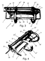
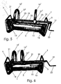
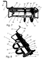
- the holding means can assume various shapes and configurations, two of which are shown, as a non-limiting example, respectively in Fig. 1-2 and in Fig. 3-8, according to the sizes and shapes of the tires to be clamped.
- the chock 1 comprises, first of all, in a known way, an elongated tubular member 3, that is used for resting the wheels 20: such elongated tubular member 3 is connected, through small rods 6, to a base member 5 to be rested onto the flatbed (not shown) and is equipped with side shoulders 7, 9 and with securing means 11, 13 to the flatbed of the transporting vehicle.
- such securing means 11, 13 are composed of an elongated pin (to be inserted into corresponding slots of the flatbed) equipped with a projection for clamping the flatbed bottom, and equipped with respective tightening and loosening levers 15, 17 that operate against the thrust of springs 16 in order to secure and keep the chock 1 clamped to the flatbed.
- such chock 1 is equipped with holding means for the wheels 20 that are composed of:
- clamping jaws 19', 19" are equipped at a first end with respective first sliding rings 21 fitted over and adapted to slide along the elongated tubular bearing member 3, and are equipped at a second end with respective second sliding rings 23 fitted over and adapted to slide along an elongated tubular sliding member 25 parallel with the elongated tubular bearing member 3 and connected to the shoulders 7, 9 of the chock 1.
- clamping jaws 19', 19" are each equipped with a respective nut 27', 27" adapted to connect them to the adjusting means 29, 31, 33 in order to allow the adjusting means 29, 31, 33 themselves to control the mutual approaching and going away movement of the jaws 19', 19" through the nuts 27', 27".
- the adjusting means 29, 31, 33 are composed of an elongated screw 29 rotatingly driven by a handle equipped with a grip 33 connected therewith through a small rod 31.
- the screw 29 extends parallel with the elongated members 3 and 25, for a length that is substantially equal to the one of such elongated members 3, 25.
- the embodiment shown provides that one (for example, 19') of the clamping jaws 19', 19" is fixed and that the nut 27' of the jaw 19' is immovably connected to the adjusting means 29, 31, 33, while the other one (for example 19") of the clamping jaws 19', 19” is movable and is adapted to approach and move away from the fixed jaw 19'.
- the fixed jaw 19' can be adjustable in its securing position.
- the ring 21 of the fixed jaw 19' is equipped with a hole (not shown) that is made correspond to one of respective holes 37 obtained in the elongated bearing member 3 of the chock 1 in order to secure the fixed jaw 19' to the elongated bearing member 3 through a pin 35 that is adapted to penetrate into the two respective coupled holes.
- the vehicle wheel 20 After having fitted the chock 1 onto the flatbed by operating on the securing means 11, 13 through the levers 15, 17, the vehicle wheel 20 is rested onto the member 3 and the fixed jaw 19' (with the chock 1 arranged as shown, for example, in Figures 3 to 5) and then the handle grip 33 is operated, making it turn and making then the movable jaw 19" slide transversally till it clamps the wheel 20 tire (where the jaws 19', 19" of the chock 1 assume, for example, the position shown in Figures 6 to 8).
- the vehicle clamping to the flatbed is then completed through common known means, such as belts, tie-rods, etc.
- a lateral hold is thereby guaranteed (with respect to the running direction of the transporting vehicle) for the vehicle wheels 20 that is very efficient.
- the chock 1 can be of the type that is able to be overturned and is able to disappear below the flatbed, and the flatbed of the transporting vehicles on which the chock 1 is secured is equipped with respective housings for containing the wheel 20 holding means when the chock 1 is in its disappeared position below the flatbed.
Landscapes
- Engineering & Computer Science (AREA)
- Health & Medical Sciences (AREA)
- Public Health (AREA)
- Transportation (AREA)
- Mechanical Engineering (AREA)
- Handcart (AREA)
Claims (12)
- Cale (1) adaptée au montage sur un véhicule de transport de véhicules, conçue pour caler les roues (20) des véhicules transportés, cette cale (1) étant pourvue de moyens de retenue pour les roues (20) des véhicules transportés, cette cale (1) comprenant un élément tubulaire allongé (3) d'appui pour les roues (20), ledit élément tubulaire allongé (3) étant relié par des tiges (6) à un élément de base (5) et étant pourvu d'épaulements latéraux (7, 9) et de moyens de fixation (11, 13) à une plate-forme de véhicule de transport, caractérisé en ce que lesdits moyens de retenue sont constitués de:- au moins deux mâchoires de prise (19', 19") capables de coopérer réciproquement en coulissant le long de l'axe de la roue (20) du véhicule pour effectuer la prise et la retenue latérale de la roue (20); et- des moyens (29, 31, 33) de réglage de la distance réciproque entre lesdites mâchoires (19', 19");- ces au moins deux mâchoires de prise (19', 19") étant pourvues d'une première extrémité de respectives premières bagues de coulissement (21) insérées dessus et capables de coulisser le long dudit élément tubulaire allongé d'appui (3) et étant pourvues à une seconde extrémité de respectives secondes bagues de coulissement (23) insérées dessus et capables de coulisser le long d'un élément tubulaire allongé (25) parallèle à l'élément tubulaire allongé d'appui (3) et relié aux épaulements (7, 9) de ladite cale (1).
- Cale (1) selon la revendication 1, caractérisée en ce que lesdits moyens de retenue sont des moyens réglables pour la prise des pneumatiques (20) des véhicules transportés.
- Cale (1) selon la revendication 1 ou 2, caractérisée en ce que lesdits véhicules transportés sont des motocycles.
- Cale (1) selon la revendication 1, caractérisée en ce que lesdites au moins deux mâchoires de prise (19', 19") sont conformées de manière à faire prise sur le pneumatique (20) sans ébrécher ni endommager la jante de la roue.
- Cale (1) selon une quelconque des revendications précédentes, caractérisée en ce que lesdites au moins deux mâchoires de prise (19', 19") sont chacune pourvues d'une écrou respectif (27', 27") pour les relier aux moyens de réglage (29, 31, 33) de manière à permettre aux moyens de réglage (29, 31, 33) de commander l'éloignement ou le rapprochement réciproque desdites mâchoires (19', 19") au moyen de ces écrous (27', 27").
- Cale (1) selon une quelconque des revendications précédentes, caractérisée en ce que lesdits moyens de réglage (29, 31, 33) sont constitués d'une vis allongée (29) commandée en rotation par une manivelle avec une poignée (33) reliée à cette manivelle par une tige (31).
- Cale (1) selon la revendication 5 ou 6, caractérisée en ce qu'une (19') desdites mâchoires de prise (19', 19") est fixe, ledit écrou (27') de ladite mâchoire (19') étant relié de façon inamovible aux moyens de réglage (29, 31, 33), alors que l'autre (19") desdites mâchoires de prise (19', 19") est mobile et capable de se rapprocher ou de s'éloigner de ladite mâchoire fixe (19').
- Cale (1) selon la revendication 7, caractérisée en ce que ladite mâchoire fixe (19') est réglable dans sa position de fixation.
- Cale (1) selon la revendication 8, caractérisée en ce que la bague (21) de ladite mâchoire fixe (19') possède un orifice à faire coïncider à un des respectifs orifices (37) pratiqués dans ledit élément allongé d'appui (3) de ladite cale (1) pour fixer ladite mâchoire fixe (19') à l'élément allongé d'appui (3) à travers un axe (35) pénétrant dans les deux respectifs orifices accouplés.
- Cale (1) selon une quelconque des revendications de 1 à 6, caractérisée en ce que lesdites mâchoires de prise (19', 19") sont toutes deux mobiles et coulissantes dans le sens transversal par rapport au sens de marche du véhicule de transport, en directions réciproquement opposées, à travers une vis de réglage (29) possédant des filets d'orientation contraire.
- Cale (1) selon une quelconque des revendications précédentes, caractérisée en ce que lesdits moyens de fixation (11, 13) possèdent des ressorts de retenue (16) et des respectifs leviers de serrage et de desserrage (15, 17).
- Cale (1) selon une quelconque des revendications précédentes, caractérisée en ce que ladite cale (1) est du type basculant escamotable, la plate-forme desdits véhicules de transport sur laquelle est fixée la cale étant pourvue d'un logement pour contenir lesdits moyens de retenue des roues (20) quand la cale (1) se trouve en position escamotable au-dessous de la plate-forme.
Applications Claiming Priority (2)
| Application Number | Priority Date | Filing Date | Title |
|---|---|---|---|
| ITTO20030732 | 2003-09-24 | ||
| ITTO20030732 ITTO20030732A1 (it) | 2003-09-24 | 2003-09-24 | Cuneo dotato di mezzi di tenuta per ruote di veicoli. |
Publications (2)
| Publication Number | Publication Date |
|---|---|
| EP1518751A1 EP1518751A1 (fr) | 2005-03-30 |
| EP1518751B1 true EP1518751B1 (fr) | 2006-07-19 |
Family
ID=30012985
Family Applications (1)
| Application Number | Title | Priority Date | Filing Date |
|---|---|---|---|
| EP20040021758 Expired - Lifetime EP1518751B1 (fr) | 2003-09-24 | 2004-09-14 | Cale avec des moyens de retenue pour roues d'un véhicule |
Country Status (3)
| Country | Link |
|---|---|
| EP (1) | EP1518751B1 (fr) |
| DE (1) | DE602004001557D1 (fr) |
| IT (1) | ITTO20030732A1 (fr) |
Family Cites Families (7)
| Publication number | Priority date | Publication date | Assignee | Title |
|---|---|---|---|---|
| DE313311C (fr) * | ||||
| US4955459A (en) * | 1989-02-28 | 1990-09-11 | Consolidated Rail Corporation | Strapless wheel chocking assembly |
| IT223351Z2 (it) * | 1991-11-26 | 1995-06-21 | Mec Di Migliore Livio Off | Dispositivo per l'arresto di una ruota di un autoveicolo, fissabile alpianale di un autocarro per il trasporto di autoveicoli. |
| US5988402A (en) * | 1998-02-27 | 1999-11-23 | Mayfield; William Rodgers | Stand for motorcycles |
| IT1308821B1 (it) * | 1999-03-19 | 2002-01-11 | Rolfo Spa | Cuneo ribaltabile per l'arresto di ruote di autoveicoli caricati suveicoli stradali, e dispositivo di arresto che utilizza tale cuneo. |
| ITRM20020387A1 (it) * | 2002-07-22 | 2004-01-22 | Prontomoto S R L | Automezzo attrezzato per il recupero e il trasporto di veicoli, in particolare veicoli a due ruote. |
| US6755599B1 (en) * | 2003-04-29 | 2004-06-29 | Randall L. Plyler | Recessed wheel chock |
-
2003
- 2003-09-24 IT ITTO20030732 patent/ITTO20030732A1/it unknown
-
2004
- 2004-09-14 DE DE200460001557 patent/DE602004001557D1/de not_active Expired - Lifetime
- 2004-09-14 EP EP20040021758 patent/EP1518751B1/fr not_active Expired - Lifetime
Also Published As
| Publication number | Publication date |
|---|---|
| ITTO20030732A1 (it) | 2003-12-23 |
| DE602004001557D1 (de) | 2006-08-31 |
| EP1518751A1 (fr) | 2005-03-30 |
Similar Documents
| Publication | Publication Date | Title |
|---|---|---|
| US9022265B2 (en) | Bicycle rack installable in a pickup truck bed or trailer | |
| US5570825A (en) | Rear mount bicycle carrier rack for motor vehicles | |
| US4934572A (en) | Lockable clamping apparatus | |
| US4111449A (en) | Bumper hitch for towing motorcycles | |
| US6012211A (en) | Wheel puller | |
| US5984339A (en) | Motorcycle towing apparatus | |
| US3720422A (en) | Mini-dolly for transporting vehicles | |
| US4785865A (en) | Mechanical device for releasing tire beads from wheel rims | |
| US3225986A (en) | Bumper carrier for a two-wheeled vehicle | |
| US7090105B2 (en) | Vehicle exterior material clamping apparatus with scissors-like closure motion | |
| US5009257A (en) | Tire breaker apparatus for all-terrain vehicle tires | |
| US7300063B1 (en) | Vehicle dolly to enable the rolling transportation of a damaged vehicle | |
| EP1518751B1 (fr) | Cale avec des moyens de retenue pour roues d'un véhicule | |
| US20180170100A1 (en) | Torque Wrench Stabilizer Tool | |
| US9663016B1 (en) | Systems and methods for a motorcycle mount | |
| US3164197A (en) | Tire tool | |
| US3074468A (en) | Device for mounting and dismounting pneumatic tires | |
| EP0112611A2 (fr) | Dispositif de traction pour pneumatiques de véhicules automobiles | |
| US20260091626A1 (en) | System and Method for Small Tire Maintenance | |
| US6135185A (en) | Tire changing device | |
| US20240166482A1 (en) | Motorcycle Loader | |
| US7350554B1 (en) | Portable tire bead breaking apparatus | |
| US20060157523A1 (en) | Bicycle carrier which can be attached to a vehicle | |
| US20140060753A1 (en) | Tire bead wedge pliers | |
| JP3721114B2 (ja) | 台車及び台車装置 |
Legal Events
| Date | Code | Title | Description |
|---|---|---|---|
| PUAI | Public reference made under article 153(3) epc to a published international application that has entered the european phase |
Free format text: ORIGINAL CODE: 0009012 |
|
| AK | Designated contracting states |
Kind code of ref document: A1 Designated state(s): AT BE BG CH CY CZ DE DK EE ES FI FR GB GR HU IE IT LI LU MC NL PL PT RO SE SI SK TR |
|
| AX | Request for extension of the european patent |
Extension state: AL HR LT LV MK |
|
| 17P | Request for examination filed |
Effective date: 20050919 |
|
| AKX | Designation fees paid |
Designated state(s): AT BE BG CH CY CZ DE DK EE ES FI FR GB GR HU IE IT LI LU MC NL PL PT RO SE SI SK TR |
|
| GRAP | Despatch of communication of intention to grant a patent |
Free format text: ORIGINAL CODE: EPIDOSNIGR1 |
|
| GRAS | Grant fee paid |
Free format text: ORIGINAL CODE: EPIDOSNIGR3 |
|
| GRAA | (expected) grant |
Free format text: ORIGINAL CODE: 0009210 |
|
| AK | Designated contracting states |
Kind code of ref document: B1 Designated state(s): AT BE BG CH CY CZ DE DK EE ES FI FR GB GR HU IE IT LI LU MC NL PL PT RO SE SI SK TR |
|
| PG25 | Lapsed in a contracting state [announced via postgrant information from national office to epo] |
Ref country code: SI Free format text: LAPSE BECAUSE OF FAILURE TO SUBMIT A TRANSLATION OF THE DESCRIPTION OR TO PAY THE FEE WITHIN THE PRESCRIBED TIME-LIMIT Effective date: 20060719 Ref country code: CZ Free format text: LAPSE BECAUSE OF FAILURE TO SUBMIT A TRANSLATION OF THE DESCRIPTION OR TO PAY THE FEE WITHIN THE PRESCRIBED TIME-LIMIT Effective date: 20060719 Ref country code: BE Free format text: LAPSE BECAUSE OF FAILURE TO SUBMIT A TRANSLATION OF THE DESCRIPTION OR TO PAY THE FEE WITHIN THE PRESCRIBED TIME-LIMIT Effective date: 20060719 Ref country code: RO Free format text: LAPSE BECAUSE OF FAILURE TO SUBMIT A TRANSLATION OF THE DESCRIPTION OR TO PAY THE FEE WITHIN THE PRESCRIBED TIME-LIMIT Effective date: 20060719 Ref country code: AT Free format text: LAPSE BECAUSE OF FAILURE TO SUBMIT A TRANSLATION OF THE DESCRIPTION OR TO PAY THE FEE WITHIN THE PRESCRIBED TIME-LIMIT Effective date: 20060719 Ref country code: PL Free format text: LAPSE BECAUSE OF FAILURE TO SUBMIT A TRANSLATION OF THE DESCRIPTION OR TO PAY THE FEE WITHIN THE PRESCRIBED TIME-LIMIT Effective date: 20060719 Ref country code: SK Free format text: LAPSE BECAUSE OF FAILURE TO SUBMIT A TRANSLATION OF THE DESCRIPTION OR TO PAY THE FEE WITHIN THE PRESCRIBED TIME-LIMIT Effective date: 20060719 Ref country code: NL Free format text: LAPSE BECAUSE OF FAILURE TO SUBMIT A TRANSLATION OF THE DESCRIPTION OR TO PAY THE FEE WITHIN THE PRESCRIBED TIME-LIMIT Effective date: 20060719 Ref country code: CH Free format text: LAPSE BECAUSE OF FAILURE TO SUBMIT A TRANSLATION OF THE DESCRIPTION OR TO PAY THE FEE WITHIN THE PRESCRIBED TIME-LIMIT Effective date: 20060719 Ref country code: FI Free format text: LAPSE BECAUSE OF FAILURE TO SUBMIT A TRANSLATION OF THE DESCRIPTION OR TO PAY THE FEE WITHIN THE PRESCRIBED TIME-LIMIT Effective date: 20060719 Ref country code: LI Free format text: LAPSE BECAUSE OF FAILURE TO SUBMIT A TRANSLATION OF THE DESCRIPTION OR TO PAY THE FEE WITHIN THE PRESCRIBED TIME-LIMIT Effective date: 20060719 |
|
| REG | Reference to a national code |
Ref country code: GB Ref legal event code: FG4D |
|
| RIN1 | Information on inventor provided before grant (corrected) |
Inventor name: ROLFO, DARIO |
|
| REG | Reference to a national code |
Ref country code: CH Ref legal event code: EP |
|
| REG | Reference to a national code |
Ref country code: IE Ref legal event code: FG4D |
|
| REF | Corresponds to: |
Ref document number: 602004001557 Country of ref document: DE Date of ref document: 20060831 Kind code of ref document: P |
|
| PG25 | Lapsed in a contracting state [announced via postgrant information from national office to epo] |
Ref country code: IE Free format text: LAPSE BECAUSE OF NON-PAYMENT OF DUE FEES Effective date: 20060914 |
|
| PG25 | Lapsed in a contracting state [announced via postgrant information from national office to epo] |
Ref country code: MC Free format text: LAPSE BECAUSE OF NON-PAYMENT OF DUE FEES Effective date: 20060930 |
|
| PG25 | Lapsed in a contracting state [announced via postgrant information from national office to epo] |
Ref country code: SE Free format text: LAPSE BECAUSE OF FAILURE TO SUBMIT A TRANSLATION OF THE DESCRIPTION OR TO PAY THE FEE WITHIN THE PRESCRIBED TIME-LIMIT Effective date: 20061019 Ref country code: BG Free format text: LAPSE BECAUSE OF FAILURE TO SUBMIT A TRANSLATION OF THE DESCRIPTION OR TO PAY THE FEE WITHIN THE PRESCRIBED TIME-LIMIT Effective date: 20061019 Ref country code: DK Free format text: LAPSE BECAUSE OF FAILURE TO SUBMIT A TRANSLATION OF THE DESCRIPTION OR TO PAY THE FEE WITHIN THE PRESCRIBED TIME-LIMIT Effective date: 20061019 |
|
| PG25 | Lapsed in a contracting state [announced via postgrant information from national office to epo] |
Ref country code: DE Free format text: LAPSE BECAUSE OF FAILURE TO SUBMIT A TRANSLATION OF THE DESCRIPTION OR TO PAY THE FEE WITHIN THE PRESCRIBED TIME-LIMIT Effective date: 20061020 |
|
| PG25 | Lapsed in a contracting state [announced via postgrant information from national office to epo] |
Ref country code: ES Free format text: LAPSE BECAUSE OF FAILURE TO SUBMIT A TRANSLATION OF THE DESCRIPTION OR TO PAY THE FEE WITHIN THE PRESCRIBED TIME-LIMIT Effective date: 20061030 |
|
| PG25 | Lapsed in a contracting state [announced via postgrant information from national office to epo] |
Ref country code: PT Free format text: LAPSE BECAUSE OF FAILURE TO SUBMIT A TRANSLATION OF THE DESCRIPTION OR TO PAY THE FEE WITHIN THE PRESCRIBED TIME-LIMIT Effective date: 20061219 |
|
| NLV1 | Nl: lapsed or annulled due to failure to fulfill the requirements of art. 29p and 29m of the patents act | ||
| EN | Fr: translation not filed | ||
| PLBE | No opposition filed within time limit |
Free format text: ORIGINAL CODE: 0009261 |
|
| STAA | Information on the status of an ep patent application or granted ep patent |
Free format text: STATUS: NO OPPOSITION FILED WITHIN TIME LIMIT |
|
| 26N | No opposition filed |
Effective date: 20070420 |
|
| PG25 | Lapsed in a contracting state [announced via postgrant information from national office to epo] |
Ref country code: GR Free format text: LAPSE BECAUSE OF FAILURE TO SUBMIT A TRANSLATION OF THE DESCRIPTION OR TO PAY THE FEE WITHIN THE PRESCRIBED TIME-LIMIT Effective date: 20061020 Ref country code: FR Free format text: LAPSE BECAUSE OF FAILURE TO SUBMIT A TRANSLATION OF THE DESCRIPTION OR TO PAY THE FEE WITHIN THE PRESCRIBED TIME-LIMIT Effective date: 20070511 |
|
| PG25 | Lapsed in a contracting state [announced via postgrant information from national office to epo] |
Ref country code: EE Free format text: LAPSE BECAUSE OF FAILURE TO SUBMIT A TRANSLATION OF THE DESCRIPTION OR TO PAY THE FEE WITHIN THE PRESCRIBED TIME-LIMIT Effective date: 20060719 |
|
| PG25 | Lapsed in a contracting state [announced via postgrant information from national office to epo] |
Ref country code: LU Free format text: LAPSE BECAUSE OF NON-PAYMENT OF DUE FEES Effective date: 20060914 Ref country code: TR Free format text: LAPSE BECAUSE OF FAILURE TO SUBMIT A TRANSLATION OF THE DESCRIPTION OR TO PAY THE FEE WITHIN THE PRESCRIBED TIME-LIMIT Effective date: 20060719 Ref country code: HU Free format text: LAPSE BECAUSE OF FAILURE TO SUBMIT A TRANSLATION OF THE DESCRIPTION OR TO PAY THE FEE WITHIN THE PRESCRIBED TIME-LIMIT Effective date: 20070120 |
|
| PG25 | Lapsed in a contracting state [announced via postgrant information from national office to epo] |
Ref country code: CY Free format text: LAPSE BECAUSE OF FAILURE TO SUBMIT A TRANSLATION OF THE DESCRIPTION OR TO PAY THE FEE WITHIN THE PRESCRIBED TIME-LIMIT Effective date: 20060719 Ref country code: FR Free format text: LAPSE BECAUSE OF FAILURE TO SUBMIT A TRANSLATION OF THE DESCRIPTION OR TO PAY THE FEE WITHIN THE PRESCRIBED TIME-LIMIT Effective date: 20060719 |
|
| GBPC | Gb: european patent ceased through non-payment of renewal fee |
Effective date: 20080914 |
|
| PG25 | Lapsed in a contracting state [announced via postgrant information from national office to epo] |
Ref country code: GB Free format text: LAPSE BECAUSE OF NON-PAYMENT OF DUE FEES Effective date: 20080914 |
|
| PG25 | Lapsed in a contracting state [announced via postgrant information from national office to epo] |
Ref country code: IT Free format text: LAPSE BECAUSE OF NON-PAYMENT OF DUE FEES Effective date: 20100914 |
|
| PGRI | Patent reinstated in contracting state [announced from national office to epo] |
Ref country code: IT Effective date: 20110616 |
|
| PGFP | Annual fee paid to national office [announced via postgrant information from national office to epo] |
Ref country code: IT Payment date: 20130911 Year of fee payment: 10 |
|
| PG25 | Lapsed in a contracting state [announced via postgrant information from national office to epo] |
Ref country code: IT Free format text: LAPSE BECAUSE OF NON-PAYMENT OF DUE FEES Effective date: 20140914 |