EP1518792B1 - Poignée renforcée et flan - Google Patents
Poignée renforcée et flan Download PDFInfo
- Publication number
- EP1518792B1 EP1518792B1 EP04020606A EP04020606A EP1518792B1 EP 1518792 B1 EP1518792 B1 EP 1518792B1 EP 04020606 A EP04020606 A EP 04020606A EP 04020606 A EP04020606 A EP 04020606A EP 1518792 B1 EP1518792 B1 EP 1518792B1
- Authority
- EP
- European Patent Office
- Prior art keywords
- handle
- handle panel
- strap member
- carton
- panel
- Prior art date
- Legal status (The legal status is an assumption and is not a legal conclusion. Google has not performed a legal analysis and makes no representation as to the accuracy of the status listed.)
- Expired - Lifetime
Links
- 230000002250 progressing effect Effects 0.000 claims description 5
- 238000000926 separation method Methods 0.000 description 2
- 230000001174 ascending effect Effects 0.000 description 1
- 230000004048 modification Effects 0.000 description 1
- 238000012986 modification Methods 0.000 description 1
Images

Classifications
-
- B—PERFORMING OPERATIONS; TRANSPORTING
- B65—CONVEYING; PACKING; STORING; HANDLING THIN OR FILAMENTARY MATERIAL
- B65D—CONTAINERS FOR STORAGE OR TRANSPORT OF ARTICLES OR MATERIALS, e.g. BAGS, BARRELS, BOTTLES, BOXES, CANS, CARTONS, CRATES, DRUMS, JARS, TANKS, HOPPERS, FORWARDING CONTAINERS; ACCESSORIES, CLOSURES, OR FITTINGS THEREFOR; PACKAGING ELEMENTS; PACKAGES
- B65D71/00—Bundles of articles held together by packaging elements for convenience of storage or transport, e.g. portable segregating carrier for plural receptacles such as beer cans or pop bottles; Bales of material
- B65D71/06—Packaging elements holding or encircling completely or almost completely the bundle of articles, e.g. wrappers
- B65D71/12—Packaging elements holding or encircling completely or almost completely the bundle of articles, e.g. wrappers the packaging elements, e.g. wrappers being formed by folding a single blank
- B65D71/36—Packaging elements holding or encircling completely or almost completely the bundle of articles, e.g. wrappers the packaging elements, e.g. wrappers being formed by folding a single blank having a tubular shape, e.g. tubular wrappers, with end walls
-
- B—PERFORMING OPERATIONS; TRANSPORTING
- B65—CONVEYING; PACKING; STORING; HANDLING THIN OR FILAMENTARY MATERIAL
- B65D—CONTAINERS FOR STORAGE OR TRANSPORT OF ARTICLES OR MATERIALS, e.g. BAGS, BARRELS, BOTTLES, BOXES, CANS, CARTONS, CRATES, DRUMS, JARS, TANKS, HOPPERS, FORWARDING CONTAINERS; ACCESSORIES, CLOSURES, OR FITTINGS THEREFOR; PACKAGING ELEMENTS; PACKAGES
- B65D5/00—Rigid or semi-rigid containers of polygonal cross-section, e.g. boxes, cartons or trays, formed by folding or erecting one or more blanks made of paper
- B65D5/42—Details of containers or of foldable or erectable container blanks
- B65D5/44—Integral, inserted or attached portions forming internal or external fittings
- B65D5/46—Handles
- B65D5/46072—Handles integral with the container
- B65D5/46192—Handles integral with the container formed by incisions in the container or blank forming straps used as handles
-
- B—PERFORMING OPERATIONS; TRANSPORTING
- B65—CONVEYING; PACKING; STORING; HANDLING THIN OR FILAMENTARY MATERIAL
- B65D—CONTAINERS FOR STORAGE OR TRANSPORT OF ARTICLES OR MATERIALS, e.g. BAGS, BARRELS, BOTTLES, BOXES, CANS, CARTONS, CRATES, DRUMS, JARS, TANKS, HOPPERS, FORWARDING CONTAINERS; ACCESSORIES, CLOSURES, OR FITTINGS THEREFOR; PACKAGING ELEMENTS; PACKAGES
- B65D71/00—Bundles of articles held together by packaging elements for convenience of storage or transport, e.g. portable segregating carrier for plural receptacles such as beer cans or pop bottles; Bales of material
- B65D71/06—Packaging elements holding or encircling completely or almost completely the bundle of articles, e.g. wrappers
- B65D71/12—Packaging elements holding or encircling completely or almost completely the bundle of articles, e.g. wrappers the packaging elements, e.g. wrappers being formed by folding a single blank
- B65D71/14—Packaging elements holding or encircling completely or almost completely the bundle of articles, e.g. wrappers the packaging elements, e.g. wrappers being formed by folding a single blank having the shape of a tube, without, or not being characterised by, end walls
- B65D71/16—Packaging elements holding or encircling completely or almost completely the bundle of articles, e.g. wrappers the packaging elements, e.g. wrappers being formed by folding a single blank having the shape of a tube, without, or not being characterised by, end walls with article-locating elements
- B65D71/20—Slits or openings along the fold line of the tubular body
-
- B—PERFORMING OPERATIONS; TRANSPORTING
- B65—CONVEYING; PACKING; STORING; HANDLING THIN OR FILAMENTARY MATERIAL
- B65D—CONTAINERS FOR STORAGE OR TRANSPORT OF ARTICLES OR MATERIALS, e.g. BAGS, BARRELS, BOTTLES, BOXES, CANS, CARTONS, CRATES, DRUMS, JARS, TANKS, HOPPERS, FORWARDING CONTAINERS; ACCESSORIES, CLOSURES, OR FITTINGS THEREFOR; PACKAGING ELEMENTS; PACKAGES
- B65D2571/00—Bundles of articles held together by packaging elements for convenience of storage or transport, e.g. portable segregating carrier for plural receptacles such as beer cans, pop bottles; Bales of material
- B65D2571/00123—Bundling wrappers or trays
- B65D2571/00129—Wrapper locking means
- B65D2571/00135—Wrapper locking means integral with the wrapper
- B65D2571/00141—Wrapper locking means integral with the wrapper glued
-
- B—PERFORMING OPERATIONS; TRANSPORTING
- B65—CONVEYING; PACKING; STORING; HANDLING THIN OR FILAMENTARY MATERIAL
- B65D—CONTAINERS FOR STORAGE OR TRANSPORT OF ARTICLES OR MATERIALS, e.g. BAGS, BARRELS, BOTTLES, BOXES, CANS, CARTONS, CRATES, DRUMS, JARS, TANKS, HOPPERS, FORWARDING CONTAINERS; ACCESSORIES, CLOSURES, OR FITTINGS THEREFOR; PACKAGING ELEMENTS; PACKAGES
- B65D2571/00—Bundles of articles held together by packaging elements for convenience of storage or transport, e.g. portable segregating carrier for plural receptacles such as beer cans, pop bottles; Bales of material
- B65D2571/00123—Bundling wrappers or trays
- B65D2571/00432—Handles or suspending means
- B65D2571/00456—Handles or suspending means integral with the wrapper
- B65D2571/00462—Straps made by two slits in a wall
-
- B—PERFORMING OPERATIONS; TRANSPORTING
- B65—CONVEYING; PACKING; STORING; HANDLING THIN OR FILAMENTARY MATERIAL
- B65D—CONTAINERS FOR STORAGE OR TRANSPORT OF ARTICLES OR MATERIALS, e.g. BAGS, BARRELS, BOTTLES, BOXES, CANS, CARTONS, CRATES, DRUMS, JARS, TANKS, HOPPERS, FORWARDING CONTAINERS; ACCESSORIES, CLOSURES, OR FITTINGS THEREFOR; PACKAGING ELEMENTS; PACKAGES
- B65D2571/00—Bundles of articles held together by packaging elements for convenience of storage or transport, e.g. portable segregating carrier for plural receptacles such as beer cans, pop bottles; Bales of material
- B65D2571/00123—Bundling wrappers or trays
- B65D2571/00432—Handles or suspending means
- B65D2571/00456—Handles or suspending means integral with the wrapper
- B65D2571/00469—Straps made between two handholes
-
- B—PERFORMING OPERATIONS; TRANSPORTING
- B65—CONVEYING; PACKING; STORING; HANDLING THIN OR FILAMENTARY MATERIAL
- B65D—CONTAINERS FOR STORAGE OR TRANSPORT OF ARTICLES OR MATERIALS, e.g. BAGS, BARRELS, BOTTLES, BOXES, CANS, CARTONS, CRATES, DRUMS, JARS, TANKS, HOPPERS, FORWARDING CONTAINERS; ACCESSORIES, CLOSURES, OR FITTINGS THEREFOR; PACKAGING ELEMENTS; PACKAGES
- B65D2571/00—Bundles of articles held together by packaging elements for convenience of storage or transport, e.g. portable segregating carrier for plural receptacles such as beer cans, pop bottles; Bales of material
- B65D2571/00123—Bundling wrappers or trays
- B65D2571/00432—Handles or suspending means
- B65D2571/00518—Handles or suspending means with reinforcements
- B65D2571/00524—Handles or suspending means with reinforcements integral
-
- B—PERFORMING OPERATIONS; TRANSPORTING
- B65—CONVEYING; PACKING; STORING; HANDLING THIN OR FILAMENTARY MATERIAL
- B65D—CONTAINERS FOR STORAGE OR TRANSPORT OF ARTICLES OR MATERIALS, e.g. BAGS, BARRELS, BOTTLES, BOXES, CANS, CARTONS, CRATES, DRUMS, JARS, TANKS, HOPPERS, FORWARDING CONTAINERS; ACCESSORIES, CLOSURES, OR FITTINGS THEREFOR; PACKAGING ELEMENTS; PACKAGES
- B65D2571/00—Bundles of articles held together by packaging elements for convenience of storage or transport, e.g. portable segregating carrier for plural receptacles such as beer cans, pop bottles; Bales of material
- B65D2571/00123—Bundling wrappers or trays
- B65D2571/00432—Handles or suspending means
- B65D2571/00537—Handles or suspending means with stress relieving means
- B65D2571/00543—Handles or suspending means with stress relieving means consisting of cut-outs, slits, or the like
-
- B—PERFORMING OPERATIONS; TRANSPORTING
- B65—CONVEYING; PACKING; STORING; HANDLING THIN OR FILAMENTARY MATERIAL
- B65D—CONTAINERS FOR STORAGE OR TRANSPORT OF ARTICLES OR MATERIALS, e.g. BAGS, BARRELS, BOTTLES, BOXES, CANS, CARTONS, CRATES, DRUMS, JARS, TANKS, HOPPERS, FORWARDING CONTAINERS; ACCESSORIES, CLOSURES, OR FITTINGS THEREFOR; PACKAGING ELEMENTS; PACKAGES
- B65D2571/00—Bundles of articles held together by packaging elements for convenience of storage or transport, e.g. portable segregating carrier for plural receptacles such as beer cans, pop bottles; Bales of material
- B65D2571/00123—Bundling wrappers or trays
- B65D2571/00432—Handles or suspending means
- B65D2571/00537—Handles or suspending means with stress relieving means
- B65D2571/00549—Handles or suspending means with stress relieving means consisting of fold lines
-
- B—PERFORMING OPERATIONS; TRANSPORTING
- B65—CONVEYING; PACKING; STORING; HANDLING THIN OR FILAMENTARY MATERIAL
- B65D—CONTAINERS FOR STORAGE OR TRANSPORT OF ARTICLES OR MATERIALS, e.g. BAGS, BARRELS, BOTTLES, BOXES, CANS, CARTONS, CRATES, DRUMS, JARS, TANKS, HOPPERS, FORWARDING CONTAINERS; ACCESSORIES, CLOSURES, OR FITTINGS THEREFOR; PACKAGING ELEMENTS; PACKAGES
- B65D2571/00—Bundles of articles held together by packaging elements for convenience of storage or transport, e.g. portable segregating carrier for plural receptacles such as beer cans, pop bottles; Bales of material
- B65D2571/00123—Bundling wrappers or trays
- B65D2571/00648—Elements used to form the wrapper
- B65D2571/00654—Blanks
- B65D2571/0066—Blanks formed from one single sheet
-
- B—PERFORMING OPERATIONS; TRANSPORTING
- B65—CONVEYING; PACKING; STORING; HANDLING THIN OR FILAMENTARY MATERIAL
- B65D—CONTAINERS FOR STORAGE OR TRANSPORT OF ARTICLES OR MATERIALS, e.g. BAGS, BARRELS, BOTTLES, BOXES, CANS, CARTONS, CRATES, DRUMS, JARS, TANKS, HOPPERS, FORWARDING CONTAINERS; ACCESSORIES, CLOSURES, OR FITTINGS THEREFOR; PACKAGING ELEMENTS; PACKAGES
- B65D2571/00—Bundles of articles held together by packaging elements for convenience of storage or transport, e.g. portable segregating carrier for plural receptacles such as beer cans, pop bottles; Bales of material
- B65D2571/00123—Bundling wrappers or trays
- B65D2571/00709—Shape of the formed wrapper, i.e. shape of each formed element if the wrapper is made from more than one element
- B65D2571/00722—Shape of the formed wrapper, i.e. shape of each formed element if the wrapper is made from more than one element tubular with end walls, e.g. walls not extending on the whole end surface
- B65D2571/00728—Shape of the formed wrapper, i.e. shape of each formed element if the wrapper is made from more than one element tubular with end walls, e.g. walls not extending on the whole end surface the end walls being closed by gluing
Definitions
- the invention relates to a handle structure for a carton, a carton comprising such a handle structure and a blank for forming such a carton.
- Handles are useful in cartons as a means for transporting the cartons.
- a problem in cartons of flexible material wherein a handle is formed in a panel of the carton is that the substantial stress forces are typically concentrated upon the handle or undesirable portions of the panel in which the handle resides. It can be appreciated that it could be desirable to have a handle structure for a carton of flexible material that does not impart significant forces upon undesirable portions of the handle or the panel in which the handle resides.
- US Patent Number 5,873,515 discloses a handle structure comprising a multi-ply handle section for a carton comprising a central hand grip formed in a top panel between first and second hand openings.
- a handle structure for a carton having a handle panel and a strap member integrally conjoined with the handle panel, which strap member has strap edges substantially disjoined from the handle panel, characterised by comprising severance line segments extending from first end points proximate each respective corner of the handle panel to second end points proximate a centrally disposed region of said strap member and in that a portion of each severance line segment defines a first edge of a respective connecting tab, and further in that additional severance lines extend from the centrally disposed region of the strap member to define second edges of the connecting tabs opposite said first edges, the connecting tabs interconnecting the strap member and adjacent regions of the handle panel such that when a force that is substantially normal to a plane in which said handle panel lies is exerted upon said centrally disposed region, said strap member is flexed outwardly of said plane to a biased position proximate said plane.
- the aforesaid first edges of the connecting tabs are spaced from the aforesaid second edges of the connecting tabs.
- the aforesaid severance lines remain unbroken until the strap member flexes outwardly of the aforesaid plane.
- each said severance line segment comprises a portion that is substantially parallel to opposing side edges of the handle panel.
- each said severance line segment diverges from a proximate one of opposing side edges of the handle panel as the severance line segment extends from said second end point to said first end point.
- gusset formed from a non-coincident pair of a score line and a perforated line disposed at each of said corners and having a first end adjacent the respective said corner and a second end adjacent said first end point of said severance line segments
- a carton having a handle structure.
- an array of cylindrical articles of a predetermined diameter are to be packaged within said carton and said first end points lie on or adjacent a tangent line at which the handle panel is tangent to a cylindrical sidewall of a body of one of the articles disposed at the respective corner of the array adjacent the handle panel.
- a second aspect of the invention provides a blank for forming a carton having a plurality of wall panels for forming the top, base, opposing sides and ends of the carton and a handle structure comprising a handle panel and a strap member integrally conjoined with the handle panel, which strap member has strap edges substantially disjoined from the handle panel, characterised by comprising severance line segments extending from first end points proximate each respective corner of the handle panel to second end points proximate a centrally disposed region of said strap member and in that a portion of each severance line segment defines a first edge of a respective connecting tab, and further in that additional lines of severance extend from the centrally disposed region of the strap member to defines second edges of the connecting tabs opposite said first edges, the connecting tabs interconnecting the strap member and adjacent regions of the dandle panel, such that when a force that is substantially normal to a plane in which said handle panel lies is exerted upon said centrally disposed region, said strap member is flexed
- each said severance line segment comprises a portion that is substantially parallel to opposing side edges of the handle panel.
- each said severance line segment diverges from a proximate one of opposing side edges of the handle panel as said severance line segment extends from said second end point to said first end point.
- gusset formed from a non-coincident pair of a score line and a perforated line disposed at each of said corners having a first end adjacent the respective said corner and a second end adjacent said first end point of said severance line segment.
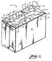
- FIG. 1 , 2 and 3 illustrate a carton 10 having a handle structure in accordance with a preferred embodiment of the invention.
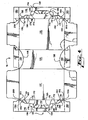
- FIG. 3 illustrates the blank 12 from which the carton of Figs. 1 and 2 is formed
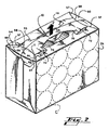
- Fig. 2 illustrates the transverse alignment of cans C with respect to the carton's 10 handle structure in accordance with a preferred embodiment of the invention.
- Fig. 2 also depicts the manner in which the top wall of the carton 10 including its handle structure bows upwardly when a force F is applied to lift the strap member 14.
- the environment of the handle structure of the invention is a carton 10 that forms an enclosure from a series of interconnected panels.
- Fig. 3 the main adjoining panels 20, 22, 24, 26 and 28 which form a tubular structure when the end-most panels 20, 28 are joined are most clearly seen.
- the end-most panels 20, 28 of the blank 12 form the top wall, or panel, of the carton 10 that contains the handle structure.
- each portion of the top panel 20, 28 is further described in segments.
- Each half-panel has a strap member 46, 44 with a tapered region 30, 38 mediate the end regions.
- the remaining portion 40, 42 of the top panel lies along a side edge of the top panel.
- Flaps 80 adjoin the end edges of the top panel.
- Each flap 80 forms at least a portion of an end wall in the erected carton.
- the strap members 46, 44 overlap, to a certain extent, and the tapered regions 30, 38 overlap fully to produce a substantially reinforced handle.
- a web extends diagonally from the vertex of a side edge and an end edge of the panel.
- the elongated webs 54 are defined by a spaced-apart pairing of a perforated line 57 extending diagonally from the aforementioned vertex and a score line 56 lying between the perforated line and the end edge of the panel 20, 28.
- the intersection of the score line 56 and perforated line 57 enhances the effectiveness of the invention.
- a connecting member 70 conjoins the strap member 46, 44 and a portion of the region 42, 40 of the top panel adjacent the strap member 46, 44. Stress upon the end region of the handle structure is more evenly directed toward the ends of the handle structure and carton through the coincidence of a severance line segment, which in this embodiment consists of an edge 72 (appearing as a cut line in the blank 12) of the strap member 46, 44 with the score line 56 of the elongated web. Further enhancement of the operation of the handle structure is achieved by termination of the edge 72 at the connecting tab 70.
- the end regions of the top panel which coincide with the end regions of the handle structure, may have an intermediate web panel 50 defined by a curved, or arcuate, score line 58, which, in the blank 12, coincides with the perforated lines 57 of the elongated webs of the handle structure.
- Another pair of intermediate web panels 60 may also be formed at the opposing side of the carton.
- the strap member 44, 46 provides a handle that directs stress toward the ends of the carton.
- the features of the handle structure which are described above cause the strap member 30, 38 and other elements upon the top panel of the carton to flex, or bow, in an outwardly-projecting predetermined manner when the carton 10 is lifted F.
- the structure of the elongated webs 54 cause the top panel 20, 28 to concavely bow in a stepped configuration, ascending inwardly, when the carton is lifted by a force, as illustrated in Fig. 2 .
- the tapered strap member 30, 38 provides a convenient, reliable handle.
- the connecting tabs 70 interconnect the strap member 46, 44 and adjacent top panel regions 42, 40. This interconnection causes the top panel 20, 28 to maintain a more contiguous configuration when the carton is lifted.
- the side regions 42, 40 of the top panel have a tendency to flex away from the strap member.
- the connecting tabs inhibit such movement and promote a more pleasing appearance and greater integrity of the top panel of the carton.
- the intermediate web panels 50, 60 enable the corners of the carton 10 to be drawn tighter when cans C or similar articles are transversely aligned in the carton with respect to the lengthwise dimension of the carton and top panel, as shown in Fig. 2 .
- the structure of the invention provides a handle that is reinforced and that directs stress away from the handle itself to the ends of the carton while helping the carton to maintain an aesthetically pleasing appearance and greater integrity when lifted.
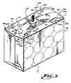
- FIG. 4 and Fig. 5 therein is shown a carton having an alternate preferred embodiment of handle structure in accordance with the teachings of the invention.
- FIGs. 4 and 5 features corresponding to like features of the preferred embodiment of the invention discussed above and illustrated in Figs. 1-3 are denoted by the same reference numerals but in a "100" series.
- panel 24 in the first embodiment is denoted as 124 in the alternate preferred embodiment.
- a first corner web 200 is formed in each corner of the top wall in which the handle structure is formed by a perforated line 190 ("perforated” in that it consists of alternating cut segments and scored segments) and a first corner score line 191 convergingly extending from the corner of the top wall or panel toward the end edge of the strap member 144.
- the various "webs” in this alternate embodiment are also for convenience of explanation sometimes hereinafter alternately referred to as "gussets" and "pleats.”
- the perforated line 190 intersects the proximate vertex of the top wall where a side edge and an end edge of the top wall intersect.
- the first corner score line 191 is disposed intermediate the perforated line 190 and the side edge of the top wall.
- a second corner score line 192 is disposed adjacent the first corner score line forming another web or gusset.
- a diagonal cut line 193 is disposed at each corner of the side wall 122, 126 adjacent the top wall in coincident alignment with the first corner score line 191.
- the severance line segment 172 which in this embodiment consists of a cut line 172 that defines each edge of the ends of the strap member may have many orientations but in the preferred alternate embodiment illustrated is optimally disposed in substantially parallel longitudinal alignment with the strap member and the side edges of the top wall.
- Tabs 1/0 that serve as handle gussets (webs/pleats) are formed by tab score lines 194, 195. Although the tab score lines may have many different alignments with respect to one another, in the preferred alternate embodiment illustrated they are nonparallel. One of the tab score lines 195 is directed toward the handhole aperture. Each tab 170 is further defined by the cut lines 172 and 196 that define the edges of the strap member.
- each cut line 172, 196 that separates the strap member structure from the remainder of the top wall and tabs 170, respectively, is interrupted by a nick member that provides joinder between these elements.
- the nick members cause the strap member 144 and tabs 170 to become separated from one another and from the top wall in a predetermined manner such that the strap member is bowed outwardly and gussets 200, 202 and 204 become angularly displaced with respect to one another.
- the first gusset 200 is displaced into condition inwardly of the outwardly-bowed strap member.
- the lifting force exerted upon the carton causes deformation which produces joinder between the diagonal cut lines and the first score lines. This deformation in turn causes the first gusset 200 to extend over the edge of the side wall of the carton.
- the arrangement of elements described directs stress to the corners of the carton. Further, when articles such as cans C are aligned in the carton, the enclosed cans at the corners of the carton adjacent the first gussets acts as a "beam" or bracing element.
- the set of nicks connecting the strap member 144 and the tabs 170 break before the set of nicks connecting the strap member proximate the tabs 170 and the remainder of the top wall.
- the primary elements of the handle structure of the subject invention are the strap member 30/38 & 130/138, disjoined from the handle panel 44/46 & 144/146, and what are referred to in this portion of the description as severance line segments 72 & 172.
- Each severance line segment extends between one point that is close to a corner of the handle panel and a second point that is close to the centrally disposed region of the strap member.
- This arrangement produces a spring like relationship between the strap member and the handle panel such that when a force F is exerted upon a centrally disposed region of the strap handle in a direction substantially perpendicular to a plane (or notional plane) in which the handle panel lies, the strap member flexes outwardly of the plane to a biased position proximate the plane, as illustrated in Figs. 2 and 5 .
- the arrangement of elements just described essentially creates a web inclusive of the pleat 70 & 170 which conjoins end regions of the strap member with the remainder of the handle panel.
- the severance line segments can be disposed in several optimal arrangements such as parallel to the side edges of the handle panel and diverging from the side panels as the severance line segment extends toward the end edges of the handle panel.
- the end point of the severance line segment that is closest the corner optimally terminates at or near a tangent line T where the end can of the array of packaged cans is tangent to the handle panel.
- Frangible members, or nick members, 74, 76 & 174, 176 are optimally disposed bridging the web that includes the pleats 70 & 170 and the strap member and bridging severance line segments 72 & 172, respectively, such that as a force that is substantially perpendicular to a notional plane of the handle panel is exerted upon the centrally disposed region of the strap member, the strap member flexes outwardly of the handle panel in a coordinated sequence beginning closest the centrally disposed region and progressing toward respective ones of the opposing edges.
- the gussets 54 & 200 previously described above serve the same function as previously described.
- the gussets extend between the end point closest the corner to the corner itself.
- the gussets can be formed from a pair of score lines, a pair of perforated lines or a combination of a non-coincident pair of a score line and a perforated line. Modifications may be made in the foregoing without departing from the scope of the claimed invention.
Landscapes
- Engineering & Computer Science (AREA)
- Mechanical Engineering (AREA)
- Cartons (AREA)
- Packages (AREA)
- Table Devices Or Equipment (AREA)
- Details Of Rigid Or Semi-Rigid Containers (AREA)
- Purses, Travelling Bags, Baskets, Or Suitcases (AREA)
- Manufacture Of Alloys Or Alloy Compounds (AREA)
- Reinforced Plastic Materials (AREA)
- Arrangement Of Elements, Cooling, Sealing, Or The Like Of Lighting Devices (AREA)
Claims (14)
- Structure de poignée destinée à un carton comportant un panneau formant poignée (40, 42; 140, 142) et un élément de liaison (44, 46; 144, 146) intégralement relié au panneau de poignée (40, 42; 140, 142), cet élément de liaison (44, 46; 144, 146) présente des bords de liaison essentiellement disjoints du panneau de poignée (40, 42; 140, 142), caractérisée en ce qu'elle comprend des segments de ligne de séparation (72; 172) s'étendant depuis les premiers points extrêmes à proximité de chaque coin respectif du panneau de poignée (40, 42; 140, 142) jusqu'aux seconds points extrêmes à proximité de la zone centrale (30, 38; 130, 138) de l'élément de liaison (44, 46; 144, 146), et en ce qu'une partie de chaque segment de ligne de séparation délimite un premier bord d'une languette de raccordement respective (70; 170), et, en outre, en ce que des lignes de séparation supplémentaires s'étendent depuis la zone centrale de l'élément de liaison de manière à délimiter les seconds bords (196) des languettes de raccordement en regard desdits premiers bords, les languettes de raccordement (70; 170) reliant l'élément de liaison (44, 46; 144, 146) aux zones adjacentes du panneau de poignée (40, 42), de sorte que lorsqu'une force essentiellement normale à un plan dans lequel se situe ledit panneau de poignée s'exerce sur ladite zone centrale (30, 38; 130, 138), ledit élément de liaison (44, 46; 144, 146) se recourbe vers l'extérieur dudit plan vers une position de sollicitation à proximité dudit plan.
- Structure de poignée telle que revendiquée dans la revendication 1, dans laquelle les susdits premiers bords des languettes de raccordement (70, 170) sont espacés par rapport aux susdits seconds bords (196) des languettes de raccordement.
- Structure de poignée telle que revendiquée dans la revendication 1 ou la revendication 2, dans laquelle les susdits segments de ligne de séparation (72; 172) restent intacts jusqu'au moment de la flexion de l'élément de liaison (44, 46; 144, 146) vers l'extérieur du susdit plan.
- Structure de poignée telle que revendiquée dans les revendications 1 à 3, dans laquelle chaque dit segment de ligne de séparation (72; 172) comporte une partie qui est essentiellement parallèle aux bords latéraux opposés du panneau de poignée (40, 42; 140, 142).
- Structure de poignée telle que revendiquée dans la revendication 1, dans laquelle une partie de chaque dit segment de ligne de séparation (72; 172) diverge du bord immédiat des bords latéraux opposés du panneau de poignée (40, 42; 140, 142) alors que le segment de ligne de séparation (72; 172) s'étend depuis ledit second point extrême jusqu'audit premier point extrême.
- Structure de poignée selon l'une quelconque des revendications précédentes, comprenant, en outre, un soufflet (54; 154) formé à partir de deux lignes de pliure (56; 156) non coïncidentes, ainsi qu'une ligne perforée (57; 157) disposée au niveau de chacun desdits coins et présentant une première extrémité contiguë audit coin respectif et une seconde extrémité contiguë audit premier point extrême dudit segment de ligne séparation (72; 172).
- Structure de poignée selon l'une quelconque des revendications précédentes, comprenant en outre plusieurs premiers éléments frangibles (74; 174) reliant lesdits bords de liaison aux parties adjacentes du panneau de poignée (40, 42; 140, 142) disposé de sorte que lorsqu'une force, exercée au carton monté et essentiellement normale à un plan fictif du panneau de poignée (40, 42; 140, 142), s'exerce sur ladite zone centrale (30, 38; 130, 138) dudit élément de liaison, ledit élément de liaison (44, 46; 144, 146) se recourbe vers l'extérieur par rapport au panneau de poignée (40, 42; 140, 142) selon une séquence coordonnée commençant le plus près de ladite zone centrale (30, 38; 130, 138) et continuant vers les bords respectifs des bords latéraux opposés du panneau de poignée.
- Structure de poignée selon l'une quelconque des revendications précédentes, comprenant en outre plusieurs éléments frangibles (76; 176) enjambant lesdits segments de ligne de séparation (72; 172) et disposés de sorte que lorsqu'une force, exercée au carton monté et essentiellement normale à un plan fictif du panneau de poignée (40, 42; 140, 142), s'exerce sur ladite zone centrale dudit élément de liaison (44, 46), ledit élément de liaison (44, 46; 144, 146) se recourbe vers l'extérieur du panneau de poignée (40, 42; 140, 142), selon une séquence coordonnée commençant le plus près de ladite zone centrale (30, 38; 130, 138) et continuant vers les bords respectifs des bords latéraux opposés du panneau de poignée.
- Carton avec une structure de poignée tel que revendiqué dans l'une quelconque des revendications précédentes.
- Carton avec une structure de poignée selon la revendication 9, dans lequel une série d'articles cylindriques (C) d'un diamètre prédéterminé doit être rangée dans ledit carton (10), et lesdits premiers points extrêmes se trouvent sur ou sont contigus à une ligne tangente (T) au niveau de laquelle le panneau de poignée est tangent à une paroi latérale cylindrique du corps de l'un des articles (C) disposés au coin respectif de la série attenant au panneau de poignée.
- Flan destiné à former un carton présentant une pluralité de panneaux de paroi pour former le dessus, le fond, les côtés opposés et les extrémités du carton, ainsi qu'une structure de poignée comportant un panneau formant poignée (40, 42; 140, 142) et un élément de liaison (44, 46; 144, 146) intégralement relié au panneau de poignée (40, 42; 140, 142), cet élément de liaison (44, 46; 144, 146) présente des bords de liaison essentiellement disjoints du panneau de poignée (40, 42; 140, 142), caractérisé en ce qu'il comprend des segments de ligne de séparation (72; 172) s'étendant depuis des premiers points extrêmes à proximité de chaque coin respectif du panneau de poignée (40, 42; 140, 142) jusqu'aux seconds points extrêmes à proximité de la zone centrale (30, 38; 130, 138) de l'élément de liaison (44, 46; 144, 146), et en ce qu'une partie de chaque segment de ligne de séparation délimite un premier bord d'une languette de raccordement respective (70; 170), et, en outre, en ce que des lignes de séparation supplémentaires s'étendent depuis la zone centrale de l'élément de liaison de manière à délimiter les seconds bords des languettes de raccordement en regard desdits premiers bords, les languettes de raccordement (70; 170) reliant l'élément de liaison (44, 46; 144, 146) aux zones adjacentes du panneau de poignée (40, 42), de sorte que lorsqu'une force essentiellement normale à un plan dans lequel se situe ledit panneau de poignée s'exerce sur ladite zone centrale (30, 38; 130, 138), ledit élément de liaison (44, 46; 144, 146) se recourbe vers l'extérieur dudit plan vers une position de sollicitation à proximité dudit plan.
- Flan tel que revendiqué dans la revendication 11, dans lequel chaque dit segment de ligne de séparation (72; 172) comprend une partie essentiellement parallèle aux bords latéraux opposés du panneau de poignée (40, 42; 140, 142).
- Flan tel que revendiqué dans la revendication 11, dans lequel une partie de chaque dit segment de ligne de séparation diverge du bord immédiat des bords latéraux opposés du panneau de poignée (40, 42; 140, 142) alors que ledit segment de ligne de séparation (72; 172) s'étend depuis ledit second point extrême jusqu'au premier point extrême.
- Flan tel que revendiqué dans l'une quelconque des revendications 11 à 13, comprenant en outre un soufflet (54; 154) formé à partir de deux lignes de pliure (56; 156) non coïncidentes et une ligne perforée (57; 157) située au niveau de chacun desdits coins et présentant une première extrémité contiguë audit coin respectif, ainsi qu'une seconde extrémité contiguë audit premier point extrême dudit segment de ligne de séparation (72; 172).
Applications Claiming Priority (7)
| Application Number | Priority Date | Filing Date | Title |
|---|---|---|---|
| US09/336,502 US6129266A (en) | 1999-06-18 | 1999-06-18 | Carton with reinforced handle structure |
| US336502 | 1999-06-18 | ||
| US382428 | 1999-08-24 | ||
| US09/382,428 US6131803A (en) | 1999-06-18 | 1999-08-24 | Carton with reinforced handle structure |
| US568231 | 2000-05-05 | ||
| US09/568,231 US6260755B1 (en) | 1999-06-18 | 2000-05-05 | Carton with reinforced handle structure |
| EP00941454A EP1105314B1 (fr) | 1999-06-18 | 2000-06-15 | Carton a structure de poignee renforcee |
Related Parent Applications (2)
| Application Number | Title | Priority Date | Filing Date |
|---|---|---|---|
| EP00941454A Division EP1105314B1 (fr) | 1999-06-18 | 2000-06-15 | Carton a structure de poignee renforcee |
| EP00941454.1 Division | 2000-06-15 |
Publications (2)
| Publication Number | Publication Date |
|---|---|
| EP1518792A1 EP1518792A1 (fr) | 2005-03-30 |
| EP1518792B1 true EP1518792B1 (fr) | 2011-05-18 |
Family
ID=27407125
Family Applications (2)
| Application Number | Title | Priority Date | Filing Date |
|---|---|---|---|
| EP04020606A Expired - Lifetime EP1518792B1 (fr) | 1999-06-18 | 2000-06-15 | Poignée renforcée et flan |
| EP00941454A Expired - Lifetime EP1105314B1 (fr) | 1999-06-18 | 2000-06-15 | Carton a structure de poignee renforcee |
Family Applications After (1)
| Application Number | Title | Priority Date | Filing Date |
|---|---|---|---|
| EP00941454A Expired - Lifetime EP1105314B1 (fr) | 1999-06-18 | 2000-06-15 | Carton a structure de poignee renforcee |
Country Status (22)
| Country | Link |
|---|---|
| EP (2) | EP1518792B1 (fr) |
| JP (1) | JP2003502230A (fr) |
| CN (1) | CN1241793C (fr) |
| AT (1) | ATE283202T1 (fr) |
| AU (2) | AU769150B2 (fr) |
| BG (1) | BG64253B1 (fr) |
| BR (1) | BR0006840A (fr) |
| CA (1) | CA2340756C (fr) |
| CZ (1) | CZ2001611A3 (fr) |
| DE (1) | DE60016145T2 (fr) |
| EE (1) | EE04334B1 (fr) |
| ES (1) | ES2232460T3 (fr) |
| HU (1) | HUP0103399A3 (fr) |
| ID (1) | ID29572A (fr) |
| IL (1) | IL141450A0 (fr) |
| NO (1) | NO20010796L (fr) |
| NZ (1) | NZ510085A (fr) |
| PL (1) | PL346225A1 (fr) |
| PT (1) | PT1105314E (fr) |
| SK (1) | SK287031B6 (fr) |
| TW (1) | TW431994B (fr) |
| WO (1) | WO2000078618A1 (fr) |
Cited By (5)
| Publication number | Priority date | Publication date | Assignee | Title |
|---|---|---|---|---|
| US8955736B2 (en) | 2012-02-16 | 2015-02-17 | Graphic Packaging International, Inc. | Carton with handle |
| US9845182B2 (en) | 2015-05-07 | 2017-12-19 | Graphic Packaging International, Inc. | Carton with handle |
| USD826711S1 (en) | 2015-10-09 | 2018-08-28 | Graphic Packaging International, Llc | Carton |
| US10384846B2 (en) | 2013-05-24 | 2019-08-20 | Graphic Packaging International, Llc | Arrangement of containers in a carton |
| US11325764B2 (en) | 2013-05-24 | 2022-05-10 | Graphic Packaging International, Llc | Carton for articles |
Families Citing this family (41)
| Publication number | Priority date | Publication date | Assignee | Title |
|---|---|---|---|---|
| CA2464719C (fr) * | 2000-10-10 | 2007-03-06 | Meadwestvaco Packaging Systems Llc | Structure de fermeture de cartonnage |
| JP4921688B2 (ja) * | 2001-04-24 | 2012-04-25 | ミードウエストヴェイコ・パッケージング・システムズ・エルエルシー | 横方向ストラップハンドルを有したカートン |
| GB0408052D0 (en) * | 2004-04-08 | 2004-05-12 | Meadwestvaco Packaging Systems | Carton and carton blank with reinforced handle structure |
| GB0413062D0 (en) * | 2004-06-11 | 2004-07-14 | Meadwestvaco Packaging Systems | Carton and carton blank with strap handle |
| US7743968B2 (en) * | 2005-08-03 | 2010-06-29 | Graphic Packaging International, Inc. | Carton having multi-ply handle |
| AU2007220970B2 (en) | 2006-03-01 | 2012-08-30 | Graphic Packaging International, Inc. | Carton with multi-ply handle |
| CN102470962B (zh) | 2009-08-17 | 2013-12-11 | 印刷包装国际公司 | 带把手的纸板箱、用于形成纸板箱的坯件和用于竖立纸板箱的方法 |
| ATE536318T1 (de) | 2009-10-30 | 2011-12-15 | Graphic Packaging Int Inc | Karton |
| MX2013003095A (es) | 2010-09-17 | 2013-10-28 | Graphic Packaging Int Inc | Caja de carton con mango. |
| EP2630057A4 (fr) | 2010-10-18 | 2014-05-07 | Graphic Packaging Int Inc | Carton ayant une poignée |
| CN104114459B (zh) | 2012-02-16 | 2017-03-08 | 印刷包装国际公司 | 带有加强把手的纸箱 |
| US9073658B2 (en) | 2012-02-27 | 2015-07-07 | Graphic Packaging International, Inc. | Carton with reinforced handle |
| GB201205243D0 (en) | 2012-03-26 | 2012-05-09 | Kraft Foods R & D Inc | Packaging and method of opening |
| EP2847086A4 (fr) | 2012-05-11 | 2015-12-09 | Graphic Packaging Int Inc | Carton avec poignée |
| WO2014025602A1 (fr) | 2012-08-10 | 2014-02-13 | Graphic Packaging International, Inc. | Carton à poignée |
| ES2621273T3 (es) * | 2012-10-24 | 2017-07-03 | Westrock Packaging Systems, Llc | Paquete con un asa en banda, asa en banda y pieza en bruto para formar un paquete con un asa en banda |
| BR112015009520B1 (pt) | 2012-11-30 | 2021-09-14 | Graphic Packaging International, Llc | Embalagem para acondicionar uma pluralidade de artigos, blanqueta para formar uma embalagem para acondicionar pelo menos um artigo, e método de formação de uma embalagem para conter pelo menos um artigo |
| WO2014124355A2 (fr) * | 2013-02-11 | 2014-08-14 | Graphic Packaging International, Inc. | Carton doté d'une poignée |
| GB2511560B (en) | 2013-03-07 | 2018-11-14 | Mondelez Uk R&D Ltd | Improved Packaging and Method of Forming Packaging |
| GB2511559B (en) | 2013-03-07 | 2018-11-14 | Mondelez Uk R&D Ltd | Improved Packaging and Method of Forming Packaging |
| CA2915257C (fr) | 2013-07-24 | 2017-10-17 | Graphic Packaging International, Inc. | Carton a poignee |
| BR112016023733B1 (pt) | 2014-05-08 | 2022-05-10 | Westrock Packaging Systems, Llc | Caixa de papelão, folha de papelão para formação da caixa e estrutura de alça para a caixa |
| WO2016028734A1 (fr) | 2014-08-19 | 2016-02-25 | Graphic Packaging International, Inc. | Carton doté de poignée renforcée |
| CA2962625C (fr) | 2014-10-27 | 2019-12-03 | Graphic Packaging International, Llc | Carton pour articles |
| CN107148388B (zh) * | 2014-10-30 | 2019-08-16 | 印刷包装国际有限责任公司 | 具有手柄的纸箱 |
| MX386877B (es) | 2014-10-31 | 2025-03-19 | Graphic Packaging Int Llc | Caja de carton con textura |
| JP2018501156A (ja) * | 2014-12-04 | 2018-01-18 | ウエストロック・パッケージング・システムズ・エルエルシー | 横方向ストラップハンドルを有するカートン |
| US10059485B2 (en) | 2015-12-08 | 2018-08-28 | Graphic Packaging International, Llc | Carton with handle |
| AU2017218126B2 (en) | 2016-02-12 | 2019-11-07 | Graphic Packaging International, Llc | Carton with handle |
| CA3012479A1 (fr) | 2016-02-12 | 2017-08-17 | Graphic Packaging International, Llc | Carton a poignee |
| CA3033378A1 (fr) * | 2016-08-08 | 2018-02-15 | Westrock Packaging Systems, Llc | Boite et decoupe comprenant une structure de renforcement de poignee |
| EP3743353B1 (fr) | 2018-01-23 | 2023-06-21 | Graphic Packaging International, LLC | Support doté d'éléments de poignée |
| USD854412S1 (en) | 2018-02-22 | 2019-07-23 | Graphic Packaging International, Llc | Carrier |
| USD867900S1 (en) | 2018-03-01 | 2019-11-26 | Graphic Packaging International, Llc | Carrier |
| AU2019249402B2 (en) | 2018-04-03 | 2022-03-17 | Graphic Packaging International, Llc | Carton |
| USD858270S1 (en) | 2018-05-04 | 2019-09-03 | Graphic Packaging International, Llc | Carton |
| USD881690S1 (en) | 2018-12-31 | 2020-04-21 | Graphic Packaging International, Llc | Carton |
| USD885887S1 (en) | 2019-01-03 | 2020-06-02 | Graphic Packaging International, Llc | Carton |
| USD898565S1 (en) | 2019-04-23 | 2020-10-13 | Graphic Packaging International, Llc | Carton |
| WO2021236499A1 (fr) | 2020-05-22 | 2021-11-25 | Graphic Packaging International, Llc | Carton pour contenants |
| USD966098S1 (en) | 2020-07-14 | 2022-10-11 | Graphic Packaging International, Llc | Carton |
Family Cites Families (8)
| Publication number | Priority date | Publication date | Assignee | Title |
|---|---|---|---|---|
| GB2239862B (en) * | 1990-01-10 | 1993-12-08 | St Regis Packaging Ltd | Improved carton and blanks therefor |
| US5333734A (en) * | 1993-08-19 | 1994-08-02 | The Mead Corporation | Heavy duty article carrier for cans arranged in a horizontal position |
| US5385234A (en) * | 1993-09-03 | 1995-01-31 | The Mead Corporation | Heavy duty article carrier |
| GB9413862D0 (en) * | 1994-07-08 | 1994-08-24 | Mead Corp | Beverage carton with strap type carrying handle |
| US5472136A (en) * | 1995-02-27 | 1995-12-05 | Waldorf Corporation | Carton with handle and deflection regions |
| US5480091A (en) * | 1995-05-11 | 1996-01-02 | The Mead Corporation | Stress-relieving arrangement for carton handles |
| US5873515A (en) | 1998-06-23 | 1999-02-23 | Riverwood International Corporation | Carton with tear control handle |
| GB9826397D0 (en) * | 1998-12-02 | 1999-01-27 | Mead Corp | Heavy duty article carrier |
-
2000
- 2000-06-15 WO PCT/US2000/016505 patent/WO2000078618A1/fr not_active Ceased
- 2000-06-15 SK SK239-2001A patent/SK287031B6/sk not_active IP Right Cessation
- 2000-06-15 EP EP04020606A patent/EP1518792B1/fr not_active Expired - Lifetime
- 2000-06-15 PL PL00346225A patent/PL346225A1/xx not_active IP Right Cessation
- 2000-06-15 DE DE60016145T patent/DE60016145T2/de not_active Expired - Lifetime
- 2000-06-15 HU HU0103399A patent/HUP0103399A3/hu unknown
- 2000-06-15 ID IDW20010659A patent/ID29572A/id unknown
- 2000-06-15 AU AU56160/00A patent/AU769150B2/en not_active Ceased
- 2000-06-15 ES ES00941454T patent/ES2232460T3/es not_active Expired - Lifetime
- 2000-06-15 EE EEP200100098A patent/EE04334B1/xx not_active IP Right Cessation
- 2000-06-15 JP JP2001504797A patent/JP2003502230A/ja active Pending
- 2000-06-15 CZ CZ2001611A patent/CZ2001611A3/cs unknown
- 2000-06-15 EP EP00941454A patent/EP1105314B1/fr not_active Expired - Lifetime
- 2000-06-15 IL IL14145000A patent/IL141450A0/xx not_active IP Right Cessation
- 2000-06-15 PT PT00941454T patent/PT1105314E/pt unknown
- 2000-06-15 BR BR0006840-3A patent/BR0006840A/pt not_active Application Discontinuation
- 2000-06-15 NZ NZ510085A patent/NZ510085A/en not_active IP Right Cessation
- 2000-06-15 AT AT00941454T patent/ATE283202T1/de not_active IP Right Cessation
- 2000-06-15 CA CA002340756A patent/CA2340756C/fr not_active Expired - Fee Related
- 2000-06-15 CN CNB008017255A patent/CN1241793C/zh not_active Expired - Fee Related
- 2000-06-17 TW TW089111916A patent/TW431994B/zh not_active IP Right Cessation
-
2001
- 2001-02-16 NO NO20010796A patent/NO20010796L/no unknown
- 2001-03-12 BG BG105333A patent/BG64253B1/bg unknown
-
2004
- 2004-04-15 AU AU2004201695A patent/AU2004201695B2/en not_active Ceased
Cited By (9)
| Publication number | Priority date | Publication date | Assignee | Title |
|---|---|---|---|---|
| US8955736B2 (en) | 2012-02-16 | 2015-02-17 | Graphic Packaging International, Inc. | Carton with handle |
| US10384846B2 (en) | 2013-05-24 | 2019-08-20 | Graphic Packaging International, Llc | Arrangement of containers in a carton |
| US11325764B2 (en) | 2013-05-24 | 2022-05-10 | Graphic Packaging International, Llc | Carton for articles |
| US9845182B2 (en) | 2015-05-07 | 2017-12-19 | Graphic Packaging International, Inc. | Carton with handle |
| USD811218S1 (en) | 2015-05-07 | 2018-02-27 | Graphic Packaging International, Inc. | Carton |
| USD824758S1 (en) | 2015-05-07 | 2018-08-07 | Graphic Packaging International, Llc | Carton |
| US10233000B2 (en) | 2015-05-07 | 2019-03-19 | Graphic Packaging International, Llc | Carton with handle |
| US10556730B2 (en) | 2015-05-07 | 2020-02-11 | Graphic Packaging International, Llc | Carton with handle |
| USD826711S1 (en) | 2015-10-09 | 2018-08-28 | Graphic Packaging International, Llc | Carton |
Also Published As
Similar Documents
| Publication | Publication Date | Title |
|---|---|---|
| EP1518792B1 (fr) | Poignée renforcée et flan | |
| US6260755B1 (en) | Carton with reinforced handle structure | |
| US5595292A (en) | Carton having shock-absorbing carrying handle and package formed therefrom | |
| US7007836B2 (en) | Paperboard carton with reinforced handle | |
| US6273330B1 (en) | Carton with transverse strap handle | |
| US5333734A (en) | Heavy duty article carrier for cans arranged in a horizontal position | |
| JP4921688B2 (ja) | 横方向ストラップハンドルを有したカートン | |
| EP1334033B1 (fr) | Carton | |
| EP0171229A2 (fr) | Emballage du type porteur pour bouteilles | |
| US6237839B1 (en) | Paperboard beverage carrier | |
| AU2001255628A1 (en) | Carton with transverse strap handle | |
| AU2001213601B2 (en) | Carton closure structure | |
| EP0879187B1 (fr) | Poignee a couches multiples pour support composite enveloppant | |
| CN101001793B (zh) | 箱体坯料 | |
| HK1076620B (en) | Handle structure and blank | |
| EP1474334B1 (fr) | Carton porte-bouteilles et decoupe d'un tel carton | |
| EP0835210B1 (fr) | Poignee pour emballages en carton | |
| MXPA01001751A (es) | Carton con estructura de asa reforzada | |
| EP0781239B1 (fr) | Porte article de haute capacite | |
| RU2250183C2 (ru) | Коробка с усиленной конструкцией ручки |
Legal Events
| Date | Code | Title | Description |
|---|---|---|---|
| PUAI | Public reference made under article 153(3) epc to a published international application that has entered the european phase |
Free format text: ORIGINAL CODE: 0009012 |
|
| 17P | Request for examination filed |
Effective date: 20040831 |
|
| AC | Divisional application: reference to earlier application |
Ref document number: 1105314 Country of ref document: EP Kind code of ref document: P |
|
| AK | Designated contracting states |
Kind code of ref document: A1 Designated state(s): AT BE CH CY DE DK ES FI FR GB GR IE IT LI LU MC NL PT SE |
|
| AX | Request for extension of the european patent |
Extension state: LT LV RO SI |
|
| AKX | Designation fees paid |
Designated state(s): AT BE CH CY DE DK ES FI FR GB GR IE IT LI LU MC NL PT SE |
|
| AXX | Extension fees paid |
Extension state: SI Payment date: 20040831 Extension state: RO Payment date: 20040831 Extension state: LV Payment date: 20040831 Extension state: LT Payment date: 20040831 |
|
| REG | Reference to a national code |
Ref country code: HK Ref legal event code: DE Ref document number: 1076620 Country of ref document: HK |
|
| RAP1 | Party data changed (applicant data changed or rights of an application transferred) |
Owner name: MEADWESTVACO PACKAGING SYSTEMS LLC |
|
| 17Q | First examination report despatched |
Effective date: 20070829 |
|
| RTI1 | Title (correction) |
Free format text: HANDLE STRUCTURE AND BLANK |
|
| GRAP | Despatch of communication of intention to grant a patent |
Free format text: ORIGINAL CODE: EPIDOSNIGR1 |
|
| RAP1 | Party data changed (applicant data changed or rights of an application transferred) |
Owner name: MEADWESTVACO PACKAGING SYSTEMS LLC |
|
| GRAS | Grant fee paid |
Free format text: ORIGINAL CODE: EPIDOSNIGR3 |
|
| GRAA | (expected) grant |
Free format text: ORIGINAL CODE: 0009210 |
|
| AC | Divisional application: reference to earlier application |
Ref document number: 1105314 Country of ref document: EP Kind code of ref document: P |
|
| AK | Designated contracting states |
Kind code of ref document: B1 Designated state(s): AT BE CH CY DE DK ES FI FR GB GR IE IT LI LU MC NL PT SE |
|
| AX | Request for extension of the european patent |
Extension state: LT LV RO SI |
|
| REG | Reference to a national code |
Ref country code: GB Ref legal event code: FG4D |
|
| REG | Reference to a national code |
Ref country code: CH Ref legal event code: EP |
|
| REG | Reference to a national code |
Ref country code: IE Ref legal event code: FG4D |
|
| REG | Reference to a national code |
Ref country code: DE Ref legal event code: R096 Ref document number: 60045995 Country of ref document: DE Effective date: 20110630 |
|
| REG | Reference to a national code |
Ref country code: NL Ref legal event code: T3 |
|
| REG | Reference to a national code |
Ref country code: PT Ref legal event code: SC4A Free format text: AVAILABILITY OF NATIONAL TRANSLATION Effective date: 20110818 |
|
| REG | Reference to a national code |
Ref country code: ES Ref legal event code: FG2A Ref document number: 2366639 Country of ref document: ES Kind code of ref document: T3 Effective date: 20111024 |
|
| LTIE | Lt: invalidation of european patent or patent extension |
Effective date: 20110518 |
|
| PG25 | Lapsed in a contracting state [announced via postgrant information from national office to epo] |
Ref country code: SE Free format text: LAPSE BECAUSE OF FAILURE TO SUBMIT A TRANSLATION OF THE DESCRIPTION OR TO PAY THE FEE WITHIN THE PRESCRIBED TIME-LIMIT Effective date: 20110518 |
|
| PG25 | Lapsed in a contracting state [announced via postgrant information from national office to epo] |
Ref country code: FI Free format text: LAPSE BECAUSE OF FAILURE TO SUBMIT A TRANSLATION OF THE DESCRIPTION OR TO PAY THE FEE WITHIN THE PRESCRIBED TIME-LIMIT Effective date: 20110518 Ref country code: AT Free format text: LAPSE BECAUSE OF FAILURE TO SUBMIT A TRANSLATION OF THE DESCRIPTION OR TO PAY THE FEE WITHIN THE PRESCRIBED TIME-LIMIT Effective date: 20110518 Ref country code: GR Free format text: LAPSE BECAUSE OF FAILURE TO SUBMIT A TRANSLATION OF THE DESCRIPTION OR TO PAY THE FEE WITHIN THE PRESCRIBED TIME-LIMIT Effective date: 20110819 Ref country code: CY Free format text: LAPSE BECAUSE OF FAILURE TO SUBMIT A TRANSLATION OF THE DESCRIPTION OR TO PAY THE FEE WITHIN THE PRESCRIBED TIME-LIMIT Effective date: 20110518 |
|
| REG | Reference to a national code |
Ref country code: HK Ref legal event code: GR Ref document number: 1076620 Country of ref document: HK |
|
| REG | Reference to a national code |
Ref country code: CH Ref legal event code: PL |
|
| PG25 | Lapsed in a contracting state [announced via postgrant information from national office to epo] |
Ref country code: DK Free format text: LAPSE BECAUSE OF FAILURE TO SUBMIT A TRANSLATION OF THE DESCRIPTION OR TO PAY THE FEE WITHIN THE PRESCRIBED TIME-LIMIT Effective date: 20110518 |
|
| PLBE | No opposition filed within time limit |
Free format text: ORIGINAL CODE: 0009261 |
|
| STAA | Information on the status of an ep patent application or granted ep patent |
Free format text: STATUS: NO OPPOSITION FILED WITHIN TIME LIMIT |
|
| REG | Reference to a national code |
Ref country code: IE Ref legal event code: MM4A |
|
| 26N | No opposition filed |
Effective date: 20120221 |
|
| PG25 | Lapsed in a contracting state [announced via postgrant information from national office to epo] |
Ref country code: LI Free format text: LAPSE BECAUSE OF NON-PAYMENT OF DUE FEES Effective date: 20110630 Ref country code: IE Free format text: LAPSE BECAUSE OF NON-PAYMENT OF DUE FEES Effective date: 20110615 Ref country code: CH Free format text: LAPSE BECAUSE OF NON-PAYMENT OF DUE FEES Effective date: 20110630 |
|
| REG | Reference to a national code |
Ref country code: DE Ref legal event code: R097 Ref document number: 60045995 Country of ref document: DE Effective date: 20120221 |
|
| PG25 | Lapsed in a contracting state [announced via postgrant information from national office to epo] |
Ref country code: MC Free format text: LAPSE BECAUSE OF NON-PAYMENT OF DUE FEES Effective date: 20110630 |
|
| PG25 | Lapsed in a contracting state [announced via postgrant information from national office to epo] |
Ref country code: LU Free format text: LAPSE BECAUSE OF NON-PAYMENT OF DUE FEES Effective date: 20110615 |
|
| PGFP | Annual fee paid to national office [announced via postgrant information from national office to epo] |
Ref country code: PT Payment date: 20140521 Year of fee payment: 15 Ref country code: IT Payment date: 20140625 Year of fee payment: 15 |
|
| PGFP | Annual fee paid to national office [announced via postgrant information from national office to epo] |
Ref country code: GB Payment date: 20150629 Year of fee payment: 16 Ref country code: ES Payment date: 20150626 Year of fee payment: 16 |
|
| REG | Reference to a national code |
Ref country code: PT Ref legal event code: MM4A Free format text: LAPSE DUE TO NON-PAYMENT OF FEES Effective date: 20151215 |
|
| PG25 | Lapsed in a contracting state [announced via postgrant information from national office to epo] |
Ref country code: IT Free format text: LAPSE BECAUSE OF NON-PAYMENT OF DUE FEES Effective date: 20150615 |
|
| PG25 | Lapsed in a contracting state [announced via postgrant information from national office to epo] |
Ref country code: PT Free format text: LAPSE BECAUSE OF NON-PAYMENT OF DUE FEES Effective date: 20151215 |
|
| REG | Reference to a national code |
Ref country code: FR Ref legal event code: PLFP Year of fee payment: 17 |
|
| PGFP | Annual fee paid to national office [announced via postgrant information from national office to epo] |
Ref country code: BE Payment date: 20160627 Year of fee payment: 17 Ref country code: NL Payment date: 20160626 Year of fee payment: 17 |
|
| PGFP | Annual fee paid to national office [announced via postgrant information from national office to epo] |
Ref country code: DE Payment date: 20160628 Year of fee payment: 17 |
|
| GBPC | Gb: european patent ceased through non-payment of renewal fee |
Effective date: 20160615 |
|
| PG25 | Lapsed in a contracting state [announced via postgrant information from national office to epo] |
Ref country code: GB Free format text: LAPSE BECAUSE OF NON-PAYMENT OF DUE FEES Effective date: 20160615 |
|
| REG | Reference to a national code |
Ref country code: FR Ref legal event code: PLFP Year of fee payment: 18 |
|
| REG | Reference to a national code |
Ref country code: DE Ref legal event code: R119 Ref document number: 60045995 Country of ref document: DE |
|
| REG | Reference to a national code |
Ref country code: NL Ref legal event code: MM Effective date: 20170701 |
|
| PG25 | Lapsed in a contracting state [announced via postgrant information from national office to epo] |
Ref country code: NL Free format text: LAPSE BECAUSE OF NON-PAYMENT OF DUE FEES Effective date: 20170701 |
|
| PG25 | Lapsed in a contracting state [announced via postgrant information from national office to epo] |
Ref country code: DE Free format text: LAPSE BECAUSE OF NON-PAYMENT OF DUE FEES Effective date: 20180103 |
|
| PG25 | Lapsed in a contracting state [announced via postgrant information from national office to epo] |
Ref country code: ES Free format text: LAPSE BECAUSE OF NON-PAYMENT OF DUE FEES Effective date: 20160616 |
|
| REG | Reference to a national code |
Ref country code: BE Ref legal event code: MM Effective date: 20170630 |
|
| REG | Reference to a national code |
Ref country code: FR Ref legal event code: PLFP Year of fee payment: 19 |
|
| PG25 | Lapsed in a contracting state [announced via postgrant information from national office to epo] |
Ref country code: BE Free format text: LAPSE BECAUSE OF NON-PAYMENT OF DUE FEES Effective date: 20170630 |
|
| PGFP | Annual fee paid to national office [announced via postgrant information from national office to epo] |
Ref country code: FR Payment date: 20180626 Year of fee payment: 19 |
|
| REG | Reference to a national code |
Ref country code: ES Ref legal event code: FD2A Effective date: 20181128 |
|
| PG25 | Lapsed in a contracting state [announced via postgrant information from national office to epo] |
Ref country code: FR Free format text: LAPSE BECAUSE OF NON-PAYMENT OF DUE FEES Effective date: 20190630 |