EP1518817A2 - Laufkatze, insbesondere Einschienenkatze mit niedriger Bauhöhe - Google Patents
Laufkatze, insbesondere Einschienenkatze mit niedriger Bauhöhe Download PDFInfo
- Publication number
- EP1518817A2 EP1518817A2 EP04022510A EP04022510A EP1518817A2 EP 1518817 A2 EP1518817 A2 EP 1518817A2 EP 04022510 A EP04022510 A EP 04022510A EP 04022510 A EP04022510 A EP 04022510A EP 1518817 A2 EP1518817 A2 EP 1518817A2
- Authority
- EP
- European Patent Office
- Prior art keywords
- trolley
- friction rollers
- impeller
- trolley according
- pair
- Prior art date
- Legal status (The legal status is an assumption and is not a legal conclusion. Google has not performed a legal analysis and makes no representation as to the accuracy of the status listed.)
- Granted
Links
Images


Classifications
-
- B—PERFORMING OPERATIONS; TRANSPORTING
- B66—HOISTING; LIFTING; HAULING
- B66C—CRANES; LOAD-ENGAGING ELEMENTS OR DEVICES FOR CRANES, CAPSTANS, WINCHES, OR TACKLES
- B66C11/00—Trolleys or crabs, e.g. operating above runways
- B66C11/02—Trolleys or crabs, e.g. operating above runways with operating gear or operator's cabin suspended, or laterally offset, from runway or track
- B66C11/04—Underhung trolleys
- B66C11/06—Underhung trolleys running on monorails
-
- B—PERFORMING OPERATIONS; TRANSPORTING
- B66—HOISTING; LIFTING; HAULING
- B66C—CRANES; LOAD-ENGAGING ELEMENTS OR DEVICES FOR CRANES, CAPSTANS, WINCHES, OR TACKLES
- B66C9/00—Travelling gear incorporated in or fitted to trolleys or cranes
- B66C9/14—Trolley or crane travel drives
Definitions
- the invention relates to a trolley, in particular Einschienenkatze with short Height, with a hoist having chassis frame, the wheels over movable on a running rail, in particular a lower flange, one in Is mounted substantially horizontally extending carrier, wherein at least one Impeller is drivable and at the bottom of the rail with the one driven impeller cooperating friction roller is arranged.
- the trolleys with a short height is a compact and space-saving
- the hoist laterally next to the rail arranged supporting carrier so that the actual load attachment means, the Load hook, can be lifted as high as possible under the carrier.
- the hoist next to the carrier results based on the Center carrier an off-center position of the net mass center of gravity of the chassis frame. Due to this off-center shift of emphasis exists in operation without payload the danger, which is opposite to the hoist on the Running rail, in particular the lower flange of a carrier, arranged wheels take off.
- a variant consists in that on the opposite side of the hoist Suspension frame a counterweight to order so the net mass center of gravity to shift back to the center of the carrier.
- a counterweight claimed on the one hand additional space and on the other hand, the weight the trolley and the carrier load unnecessarily increased.
- US 3,212,455 discloses a monorail trolley, in which on the underside the running rail in each case opposite an impeller to prevent a undesired tendency a friction roller to the bottom of the rail can be adjusted.
- the friction roller can be pivoted by adjusting a screw to the Distance between the respective roller and to adjust, depending on the rail to prevent the tendency.
- the present invention seeks to provide a trolley of to create the aforementioned type, the reliable construction with a simple design Reduction of the slip of the driven impeller ensured.
- the solution of this task is characterized in that a pair Friction rollers is provided, which via an adjustment of the distance to each other a common pressing mechanism to the underside of the rail are adjustable.
- both friction rollers of each pair of friction rollers symmetrical to the axis of rotation of respective impeller disposed below the impeller, whereby both friction rollers a friction roller pair always have an equal radial load and for a even pressure of the impeller on serving as a rail Provide under flange of the carrier.
- each pair of friction rollers can be fixed via a support rod to the chassis frame, the preferably two pivotable about a common axis two-armed lever comprising a friction roller rotatable at a free end of each lever is stored.
- This scissor-type construction of the support linkage is not just constructive particularly easy and cheap to manufacture, it is also beyond very flexible, since the distance between the two friction rollers of the pair of friction rollers is adjustable to each other, so that the construction is independent of the thickness the running rail, in particular the flange thickness of the lower flange, can be used and this is customizable.
- the other two free ends the lever of the support linkage via a spring-loaded pressure mechanism connected by the position of the friction rollers of the friction roller pair and their contact pressure on the underside of the running rail, in particular of the lower flange, is adjustable.
- the pressure mechanism preferably consists of one of the two free ends the lever interconnecting screw and one can be placed on the screw and a spring tensionable spring.
- this mechanism offers the Possibility to adjust the friction rollers stepless within wide limits and over the Choice of spring length and their characteristic to vary the contact pressure.
- each pair of friction rollers on a traverse arranged transversely to the travel direction on the chassis frame is determinable.
- the trusses preferably the trusses acts, the right and left of the carrier arranged parts of the chassis frame connect together, requires the installation of the friction roller pair bearing Support linkage no additional components, which in the elimination of the installation of the Friction roller pair would not be required.
- the positioning of the Supporting linkage on the traverse via a spacer tube that can be placed on the traverse via a spacer tube that can be placed on the traverse.
- the support rod is about one on the traverse, for example by means of a threaded pin or a Grub screw, fixable adjusting ring positioned exactly on the traverse.
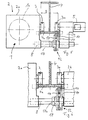
- the trolley shown in Figures 1 and 2 in front view and plan view consists essentially of a chassis 1 containing a chassis frame 2, the four impellers 3, 3a along a formed as a lower flange 4a
- Running rail of a substantially horizontally extending I-shaped support. 4 is movable, wherein an impeller 3a is driven by a traction drive 5.
- a plurality of impellers may also be used the one drive 5 or each separate drives are driven.
- the Trolley is also in conjunction with other carriers such as Box girders usable, provided that the running rail has a cross section, the opposite running surfaces for the wheels 3, 3a and later has described friction rollers 10.
- the chassis frame 2 of illustrated Einschienenkatze a particularly low height is achieved in that the chassis frame 2 of two Frame parts 2a and 2b is formed, which on both sides next to the carrier. 4 are arranged.
- the two frame parts 2 a and 2 b of the chassis frame 2 are over transverse to the direction of travel of the trolley trusses 8 rigid connected with each other.
- FIG. 4 shows the construction of the pair of friction rollers and its positioning on the Take trolley.
- the friction roller pair via a support rod 12 on the chassis frame 2 can be fixed, the two of a common axis 13 pivotable two-armed levers 14 consists.
- the both friction rollers 10 of the friction roller pair are each at a free end of a each lever 14 of the scissors-like support rod 12 rotatably mounted.
- the lever 14th in the region of the pivot axis 13, a bore 15, via which the support rod 12 rotatably mounted on one of the trusses 8, the two frame parts 2a and 2b connect together.
- this is Support rod 12 mounted on the front in Figure 2 front cross member 8 and how from Figures 2 and 3 can be seen positioned so that it is centered under the driven Impeller 3a is arranged and the two friction rollers 10 of the pair of friction rollers are arranged symmetrically to the axis of rotation 3b of the impeller 3a.
- the positioning of the support rod 12 on the cross member 8 is constructive particularly advantageous, since the storage of the support rod 12 no additional Components are required, not the omission of the support rod 12 would be required.
- FIGS. 5 and 6 show two variants, such as the support rod 12 position accurately positioned below the driven impeller 4a on the traverse 8 can be.
- the Positioning of the support rod 12 via an attachable to the crossbar 8 Distance tube 17, which on the one hand on the frame part 2a and on the other hand to the Levers 14 of the support rod 12 is supported.
- the support linkage 12 via an attachable to the crossbar 8 and the support rod 12th adjacent adjusting ring 18 is positioned, wherein the adjusting ring 18, for example via a threaded pin 18a or a grub screw 18a on the crossbar 8 fixed is.
- the compression spring 16b of the pressure mechanism 16 is further shortened until the above the support linkage 12 arranged driven wheel 3a with its tread in contact with the Bottom flange 4a of the carrier 4 occurs. This is the zero position of the radial load of the driven impeller 3a.
- the compression spring 16b is further biased until the driven impeller 3a at Accelerating the traction drive 5 no longer slips. In this position has the compression spring 16b of the pressure mechanism 16 still sufficient distance to maximum clamping position, to further biasing even in wet or oily running surface of the lower flange 4a to avoid slipping.
- the length and characteristic of the compression spring 16b can be chosen so that the Support rod 12 and thus the pair of friction rollers on commercial flange thicknesses is adjustable.
- the trolley described above is characterized in that the Friction roller arrangement very compact, space-saving and easy to install designed is.
Landscapes
- Engineering & Computer Science (AREA)
- Mechanical Engineering (AREA)
- Carriers, Traveling Bodies, And Overhead Traveling Cranes (AREA)
- Railway Tracks (AREA)
- Platform Screen Doors And Railroad Systems (AREA)
Abstract
Description
- Figur 1
- eine schematische Vorderansicht einer Laufkatze;
- Figur 2
- eine Draufsicht auf die Laufkatze gemäß Figur 1 jedoch ohne Träger;
- Figur 3
- einen Schnitt entlang der Schnittlinie III-III gemäß Figur 1;
- Figur 4
- eine perspektivische Seitenansicht eines Stützgestänges mit Reibrollenpaar;
- Figur 5
- eine im Wesentlichen der Figur 1 entsprechende Vorderansicht, eine erste Ausführungsform der Positionierung des Stützgestänges darstellend und
- Fig. 6
- eine ausschnittsweise Ansicht gemäß Figur 5, jedoch eine zweite Ausführungsform der Positionierung des Stützgestänges darstellend.
- 1
- Hubwerk
- 1 a
- Seiltrommel
- 2
- Fahrwerkrahmen
- 2a
- Rahmenteil
- 2b
- Rahmenteil
- 3
- Laufrad
- 3a
- angetriebenes Laufrad
- 3b
- Achse
- 4
- Träger
- 4a
- Unterflansch
- 4b
- Unterseite
- 4c
- Flanke
- 5
- Fahrantrieb
- 6
- Lasthaken
- 7
- Seilzug
- 8
- Traverse
- 9
- Einscherungsteil
- 10
- Reibrolle
- 11
- Führungsrolle
- 12
- Stützgestänge
- 13
- Achse
- 14
- Hebel
- 15
- Bohrung
- 16
- Andrückmechanismus
- 16a
- Schraube
- 16b
- Druckfeder
- 16c
- Mutter
- 17
- Distanzrohr
- 18
- Stellring
- 18a
- Gewindestift
- B
- Flanschbreite
Claims (10)
- Laufkatze, insbesondere Einschienenkatze mit kurzer Bauhöhe, mit einem ein Hubwerk (1) aufweisenden Fahrwerkrahmen (2), der über Laufräder (3, 3a) verfahrbar auf einer Fahrschiene, insbesondere einem Unterflansch (4a), eines im Wesentlichen horizontal verlaufenden Trägers (4) gelagert ist, wobei mindestens ein Laufrad (3a) antreibbar ist und an der Unterseite (4b) der Fahrschiene eine mit dem angetriebenen Laufrad (3a) zusammenwirkende Reibrolle (10) angeordnet ist,
dadurch gekennzeichnet, dass ein Paar Reibrollen (10) vorgesehen ist, die über eine Einstellung des Abstandes zueinander über einen gemeinsamen Andrückmechanismus an die Unterseite (4b) der Fahrschiene anstellbar sind. - Laufkatze nach Anspruch 1, dadurch gekennzeichnet, dass die beiden Reibrollen (10) eines jeden Reibrollenpaares symmetrisch zur Drehachse (3b) des jeweiligen Laufrades (3a) unterhalb des Laufrades (3a) angeordnet sind.
- Laufkatze nach Anspruch 1 oder 2, dadurch gekennzeichnet, dass jedes Reibrollenpaar über ein Stützgestänge (12) am Fahrwerkrahmen (2) festlegbar ist.
- Laufkatze nach Anspruch 3, dadurch gekennzeichnet, dass das Stützgestänge (12) zwei um eine gemeinsame Achse (13) verschwenkbare zweiarmige Hebel (14) umfasst, wobei an einem freien Ende eines jeden Hebels (14) eine Reibrolle (10) drehbar gelagert ist.
- Laufkatze nach Anspruch 4, dadurch gekennzeichnet, dass die beiden anderen freien Enden der Hebel (14) des Stützgestänges (12) über einen federbelasteten Andrückmechanismus (16) miteinander verbunden sind.
- Laufkatze nach Anspruch 5, dadurch gekennzeichnet, dass der Andrückmechanismus (16) aus einer die beiden freien Enden der Hebel (14) miteinander verbindenden Schraube (16a) und einer auf die Schraube (16a) aufsetzbaren und über eine Mutter (16c) spannbaren Druckfeder (16b) besteht.
- Laufkatze nach mindestens einem der Ansprüche 3 bis 6, dadurch gekennzeichnet, dass das Stützgestänge (12) eines jeden Reibrollenpaares an einer quer zur Verfahrrichtung am Fahrwerkrahmen (2) angeordneten Traverse (8) festlegbar ist.
- Laufkatze nach Anspruch 7, dadurch gekennzeichnet, dass das Stützgestänge (12) über ein auf die Traverse (8) aufsetzbares Distanzrohr (17) auf der Traverse (8) positionierbar ist.
- Laufkatze nach Anspruch 7, dadurch gekennzeichnet, dass das Stützgestänge (12) über einen auf der Traverse (8) festlegbaren Stellring (18) auf der Traverse (8) positionierbar ist.
- Laufkatze nach mindestens einem der Ansprüche 1 bis 9, dadurch gekennzeichnet, dass unterhalb aller Laufräder (3), die in Verfahrrichtung in einer Reihe mit dem mindestens einen angetriebenen Laufrad (3a) angeordnet sind, ein nicht angetriebenes Reibrollenpaar angeordnet ist.
Applications Claiming Priority (2)
| Application Number | Priority Date | Filing Date | Title |
|---|---|---|---|
| DE10345102 | 2003-09-26 | ||
| DE10345102A DE10345102B4 (de) | 2003-09-26 | 2003-09-26 | Laufkatze, insbesondere Einschienenkatze mit niedriger Bauhöhe |
Publications (3)
| Publication Number | Publication Date |
|---|---|
| EP1518817A2 true EP1518817A2 (de) | 2005-03-30 |
| EP1518817A3 EP1518817A3 (de) | 2006-03-29 |
| EP1518817B1 EP1518817B1 (de) | 2007-06-20 |
Family
ID=34178006
Family Applications (1)
| Application Number | Title | Priority Date | Filing Date |
|---|---|---|---|
| EP04022510A Expired - Lifetime EP1518817B1 (de) | 2003-09-26 | 2004-09-22 | Laufkatze, insbesondere Einschienenkatze mit niedriger Bauhöhe |
Country Status (6)
| Country | Link |
|---|---|
| US (1) | US7234400B2 (de) |
| EP (1) | EP1518817B1 (de) |
| CN (1) | CN100351165C (de) |
| AT (1) | ATE365142T1 (de) |
| DE (2) | DE10345102B4 (de) |
| ES (1) | ES2289408T3 (de) |
Cited By (4)
| Publication number | Priority date | Publication date | Assignee | Title |
|---|---|---|---|---|
| CN102718142A (zh) * | 2012-05-15 | 2012-10-10 | 湖州洋西起重设备有限公司 | 电缆拖令 |
| CN104787674A (zh) * | 2015-03-31 | 2015-07-22 | 浙江冠林机械有限公司 | 一种单轨小车及其使用方法 |
| EP2082941B1 (de) * | 2008-01-26 | 2017-09-20 | Eisenmann SE | Elektrohängebahn |
| CN120681189A (zh) * | 2025-08-26 | 2025-09-23 | 西安博深安全科技股份有限公司 | 矿用巡检机器人传动压紧滚轮刹车装置 |
Families Citing this family (34)
| Publication number | Priority date | Publication date | Assignee | Title |
|---|---|---|---|---|
| DE102005042988B3 (de) * | 2005-09-09 | 2007-01-04 | Abus Kransysteme Gmbh | Laufkatze |
| CN102674152A (zh) * | 2012-06-04 | 2012-09-19 | 安徽三雕起重机械有限公司 | 手拉单轨行车的平衡装置 |
| CN102897661A (zh) * | 2012-10-24 | 2013-01-30 | 中船华南船舶机械有限公司 | 起重机滑车 |
| CN103010950A (zh) * | 2012-12-12 | 2013-04-03 | 洛阳卡瑞起重设备有限公司 | 一种悬挂式起重设备的恒压摩擦驱动运行小车及方法 |
| US9353601B2 (en) * | 2013-02-12 | 2016-05-31 | Nabors Drilling USA | Articulation festoon cabling beams |
| FI126273B (fi) | 2014-01-24 | 2016-09-15 | Konecranes Global Oy | Köysinostimen matalarakenteinen nostovaunu |
| FI126272B (fi) * | 2014-01-24 | 2016-09-15 | Konecranes Global Oy | Köysinostimen matalarakenteinen nostovaunu |
| DE102014117561A1 (de) * | 2014-11-28 | 2016-06-02 | Terex Mhps Gmbh | Laufkatze für ein Hebezeug |
| US10597265B2 (en) * | 2015-11-06 | 2020-03-24 | High Concrete Group, Llc | Slider for use with a crane |
| FI127424B (fi) * | 2016-03-29 | 2018-05-31 | Konecranes Global Oy | Nosturin nostovaunu |
| CN105668411A (zh) * | 2016-04-15 | 2016-06-15 | 藤县顺舟造船有限公司 | 一种船用车间行车导轨平移机构 |
| CN105905801B (zh) * | 2016-06-02 | 2017-11-03 | 成都飞机工业(集团)有限责任公司 | 一种防止起重机在悬挂轨道上运行时打滑的装置 |
| CN110248857A (zh) * | 2016-11-29 | 2019-09-17 | 雷勃美国公司 | 用于运输系统的载运组件 |
| DE102016123863A1 (de) * | 2016-12-08 | 2018-06-14 | Eisenmann Se | Hängebahn für die Förderung von Schwerlasten |
| CN107311035A (zh) * | 2017-07-31 | 2017-11-03 | 江苏艾锐克起重装备有限公司 | 一种铝轨电驱动小车 |
| FI127807B (fi) * | 2017-09-22 | 2019-02-28 | Konecranes Global Oy | Nosturin nostimen nostojärjestely |
| FI127757B (fi) * | 2017-09-22 | 2019-02-15 | Konecranes Global Oy | Nosturin nostovaunu |
| CN110182305B (zh) * | 2019-05-31 | 2021-02-02 | 上海江南长兴造船有限责任公司 | 一种用于船舶吊口区域的移动式吊梁及使用方法 |
| CN110834899B (zh) * | 2019-11-21 | 2021-08-06 | 泉州台商投资区明云机械有限公司 | 一种轨道输送架 |
| CN111216743B (zh) * | 2020-01-14 | 2021-09-03 | 中煤科工集团重庆研究院有限公司 | 矿用轨道式巡检机器人爬坡辅助装置 |
| CN113428778A (zh) * | 2020-03-23 | 2021-09-24 | 广东博智林机器人有限公司 | 附着支座及升降架系统 |
| CN111634809A (zh) * | 2020-06-17 | 2020-09-08 | 南通力福通起重机械有限公司 | 一种轨道反压轮装置 |
| CN112110339A (zh) * | 2020-09-14 | 2020-12-22 | 百事特设备租赁(上海)股份有限公司 | 一种轨道行走装置和悬轨吊装设备 |
| US20240140761A1 (en) * | 2020-12-28 | 2024-05-02 | Ashir Vaish | A novel load transportation system |
| CN113060653A (zh) * | 2021-03-18 | 2021-07-02 | 安徽春华智能科技有限公司 | 一种便于安装的电动单梁欧式起重机 |
| CN113460108B (zh) * | 2021-08-23 | 2024-07-02 | 中冶华天南京工程技术有限公司 | 一种移动aod台车车轮行走机构的平衡装置 |
| GB202301071D0 (en) | 2023-01-25 | 2023-03-08 | Heavy Lift Projects Ltd | Ring crane with hydraulic slewing drive |
| US20250051146A1 (en) * | 2023-08-11 | 2025-02-13 | Columbus Mckinnon Corporation | Low Headroom Hook Block for Wire Rope Hoist |
| WO2025189325A1 (en) | 2024-03-12 | 2025-09-18 | Konecranes Global Corporation | Trolley and crane system |
| WO2025189326A1 (en) | 2024-03-12 | 2025-09-18 | Konecranes Global Corporation | Trolley and crane system |
| WO2025189323A1 (en) | 2024-03-12 | 2025-09-18 | Konecranes Global Corporation | Mounting arrangement for crane hoist |
| WO2025189322A1 (en) | 2024-03-12 | 2025-09-18 | Konecranes Global Corporation | Trolley and crane system |
| WO2025189327A1 (en) | 2024-03-12 | 2025-09-18 | Konecranes Global Corporation | Lifting member fixing and attachment arrangement for crane hoist |
| WO2025189324A1 (en) | 2024-03-12 | 2025-09-18 | Konecranes Global Corporation | Mounting arrangement for crane hoist |
Family Cites Families (10)
| Publication number | Priority date | Publication date | Assignee | Title |
|---|---|---|---|---|
| US3074354A (en) | 1958-05-28 | 1963-01-22 | Cleveland Crane Eng | Overhead material handling trolleys |
| GB1074773A (en) | 1963-07-15 | 1967-07-05 | Big Rock Mountain Corp | Aerial tramway system |
| US3212455A (en) * | 1963-08-08 | 1965-10-19 | Gardner Denver Co | Hoist trolley antitilting means |
| US3854407A (en) * | 1973-04-04 | 1974-12-17 | Skytram Syst Inc | Aerial tramway vehicle drive and control system |
| DE4109971C2 (de) | 1991-03-22 | 1994-05-26 | Mannesmann Ag | Einschienenbahn-Unterflansch-Fahrwerk |
| JP2607982B2 (ja) * | 1991-05-30 | 1997-05-07 | 日大工業株式会社 | 電着塗装装置 |
| DE4209565C2 (de) * | 1992-03-20 | 1995-01-19 | Mannesmann Ag | Laufkatze, insbesondere Einschienenkatze mit kurzer Bauhöhe |
| DE4312908C2 (de) * | 1993-04-13 | 1997-05-28 | Mannesmann Ag | Reibradantrieb für Laufkatze, insbesondere Einschienenkatze, mit kurzer Bauhöhe |
| US5419260A (en) * | 1993-12-15 | 1995-05-30 | Hamilton; James | Self-propelled overhead track-mounted moving system |
| US6840393B2 (en) * | 2003-03-10 | 2005-01-11 | Hsueh-Chuan Tu | Crane assembly |
-
2003
- 2003-09-26 DE DE10345102A patent/DE10345102B4/de not_active Expired - Fee Related
-
2004
- 2004-09-21 US US10/945,583 patent/US7234400B2/en not_active Expired - Lifetime
- 2004-09-22 AT AT04022510T patent/ATE365142T1/de not_active IP Right Cessation
- 2004-09-22 DE DE502004004124T patent/DE502004004124D1/de not_active Expired - Lifetime
- 2004-09-22 EP EP04022510A patent/EP1518817B1/de not_active Expired - Lifetime
- 2004-09-22 ES ES04022510T patent/ES2289408T3/es not_active Expired - Lifetime
- 2004-09-22 CN CNB2004100118211A patent/CN100351165C/zh not_active Expired - Fee Related
Cited By (4)
| Publication number | Priority date | Publication date | Assignee | Title |
|---|---|---|---|---|
| EP2082941B1 (de) * | 2008-01-26 | 2017-09-20 | Eisenmann SE | Elektrohängebahn |
| CN102718142A (zh) * | 2012-05-15 | 2012-10-10 | 湖州洋西起重设备有限公司 | 电缆拖令 |
| CN104787674A (zh) * | 2015-03-31 | 2015-07-22 | 浙江冠林机械有限公司 | 一种单轨小车及其使用方法 |
| CN120681189A (zh) * | 2025-08-26 | 2025-09-23 | 西安博深安全科技股份有限公司 | 矿用巡检机器人传动压紧滚轮刹车装置 |
Also Published As
| Publication number | Publication date |
|---|---|
| EP1518817B1 (de) | 2007-06-20 |
| EP1518817A3 (de) | 2006-03-29 |
| DE10345102B4 (de) | 2005-09-29 |
| ES2289408T3 (es) | 2008-02-01 |
| DE502004004124D1 (de) | 2007-08-02 |
| CN1600667A (zh) | 2005-03-30 |
| CN100351165C (zh) | 2007-11-28 |
| US7234400B2 (en) | 2007-06-26 |
| DE10345102A1 (de) | 2005-05-12 |
| ATE365142T1 (de) | 2007-07-15 |
| US20050092201A1 (en) | 2005-05-05 |
Similar Documents
| Publication | Publication Date | Title |
|---|---|---|
| EP1518817B1 (de) | Laufkatze, insbesondere Einschienenkatze mit niedriger Bauhöhe | |
| EP0566837B1 (de) | Kurvengurtförderer | |
| DE2636160A1 (de) | Endlosfoerderer | |
| EP0983897A2 (de) | Hebevorrichtung | |
| EP0501254A2 (de) | Scherenhubtisch | |
| CH682686A5 (de) | Anlage zum mehrstöckigen Parkieren von Fahrzeugen. | |
| DE69920783T2 (de) | Krafthebevorrichtung für Fahrzeuge | |
| DE19713500C1 (de) | Fahrwerk einer schienenverfahrbaren Hebevorrichtung | |
| DE3432207A1 (de) | Seitlich verschiebbare gabelhalterung fuer einen gabelstapler | |
| CH638731A5 (de) | Schienenfahrzeug. | |
| DE3786850T2 (de) | Einrichtung zum Be- und Entladen von palettierten Gegenständen in und aus wärmeisolierten Lieferwagen oder Containern. | |
| EP2931650B1 (de) | Kettenzug mit verbessertem ketteneinlauf | |
| DE2250428B2 (de) | Hebegerät für Fahrzeuge, insbesondere Kraftfahrzeuge | |
| WO1998043856A2 (de) | Hebevorrichtung für kraftfahrzeuge und fahrzeuganhänger, insbesondere ein wagenheber | |
| EP0391247A2 (de) | Gurtförderer | |
| EP2013134B1 (de) | Hubtischm, insbesondere für kleine hubhöhen | |
| EP3224192B1 (de) | Laufkatze für ein hebezeug | |
| EP0473953B1 (de) | Gurtförderer | |
| EP1190981B1 (de) | Scherenhubtisch | |
| DE3921123A1 (de) | Trolleyfahrzeug zum ein- und auslagern von speicherguttragenden ladungstraegern | |
| DE3907440C2 (de) | ||
| EP2604472A1 (de) | Hubladebühne | |
| DE19844304C1 (de) | Kettenförderer für Transportgut | |
| DE4237776C2 (de) | Kette zum Übertragen von Bewegungen und/oder Kräften | |
| DE69923104T2 (de) | Mittel zum Verstellen von der horizontalen Basisachse von Vorrichtungen für Gabelhubwagen oder ähnlichem |
Legal Events
| Date | Code | Title | Description |
|---|---|---|---|
| PUAI | Public reference made under article 153(3) epc to a published international application that has entered the european phase |
Free format text: ORIGINAL CODE: 0009012 |
|
| AK | Designated contracting states |
Kind code of ref document: A2 Designated state(s): AT BE BG CH CY CZ DE DK EE ES FI FR GB GR HU IE IT LI LU MC NL PL PT RO SE SI SK TR |
|
| AX | Request for extension of the european patent |
Extension state: AL HR LT LV MK |
|
| PUAL | Search report despatched |
Free format text: ORIGINAL CODE: 0009013 |
|
| AK | Designated contracting states |
Kind code of ref document: A3 Designated state(s): AT BE BG CH CY CZ DE DK EE ES FI FR GB GR HU IE IT LI LU MC NL PL PT RO SE SI SK TR |
|
| AX | Request for extension of the european patent |
Extension state: AL HR LT LV MK |
|
| RIC1 | Information provided on ipc code assigned before grant |
Ipc: B66C 9/14 20060101AFI20041019BHEP Ipc: B66C 11/06 20060101ALI20060208BHEP |
|
| 17P | Request for examination filed |
Effective date: 20060509 |
|
| 17Q | First examination report despatched |
Effective date: 20060822 |
|
| AKX | Designation fees paid |
Designated state(s): AT BE BG CH CY CZ DE DK EE ES FI FR GB GR HU IE IT LI LU MC NL PL PT RO SE SI SK TR |
|
| GRAP | Despatch of communication of intention to grant a patent |
Free format text: ORIGINAL CODE: EPIDOSNIGR1 |
|
| GRAS | Grant fee paid |
Free format text: ORIGINAL CODE: EPIDOSNIGR3 |
|
| GRAA | (expected) grant |
Free format text: ORIGINAL CODE: 0009210 |
|
| AK | Designated contracting states |
Kind code of ref document: B1 Designated state(s): AT BE BG CH CY CZ DE DK EE ES FI FR GB GR HU IE IT LI LU MC NL PL PT RO SE SI SK TR |
|
| REG | Reference to a national code |
Ref country code: GB Ref legal event code: FG4D Free format text: NOT ENGLISH |
|
| REG | Reference to a national code |
Ref country code: CH Ref legal event code: EP |
|
| REG | Reference to a national code |
Ref country code: IE Ref legal event code: FG4D Free format text: LANGUAGE OF EP DOCUMENT: GERMAN |
|
| REF | Corresponds to: |
Ref document number: 502004004124 Country of ref document: DE Date of ref document: 20070802 Kind code of ref document: P |
|
| PG25 | Lapsed in a contracting state [announced via postgrant information from national office to epo] |
Ref country code: SE Free format text: LAPSE BECAUSE OF FAILURE TO SUBMIT A TRANSLATION OF THE DESCRIPTION OR TO PAY THE FEE WITHIN THE PRESCRIBED TIME-LIMIT Effective date: 20070920 |
|
| GBT | Gb: translation of ep patent filed (gb section 77(6)(a)/1977) |
Effective date: 20070926 |
|
| PG25 | Lapsed in a contracting state [announced via postgrant information from national office to epo] |
Ref country code: PL Free format text: LAPSE BECAUSE OF FAILURE TO SUBMIT A TRANSLATION OF THE DESCRIPTION OR TO PAY THE FEE WITHIN THE PRESCRIBED TIME-LIMIT Effective date: 20070620 |
|
| NLV1 | Nl: lapsed or annulled due to failure to fulfill the requirements of art. 29p and 29m of the patents act | ||
| ET | Fr: translation filed | ||
| REG | Reference to a national code |
Ref country code: IE Ref legal event code: FD4D |
|
| PG25 | Lapsed in a contracting state [announced via postgrant information from national office to epo] |
Ref country code: PT Free format text: LAPSE BECAUSE OF FAILURE TO SUBMIT A TRANSLATION OF THE DESCRIPTION OR TO PAY THE FEE WITHIN THE PRESCRIBED TIME-LIMIT Effective date: 20071120 Ref country code: CZ Free format text: LAPSE BECAUSE OF FAILURE TO SUBMIT A TRANSLATION OF THE DESCRIPTION OR TO PAY THE FEE WITHIN THE PRESCRIBED TIME-LIMIT Effective date: 20070620 Ref country code: NL Free format text: LAPSE BECAUSE OF FAILURE TO SUBMIT A TRANSLATION OF THE DESCRIPTION OR TO PAY THE FEE WITHIN THE PRESCRIBED TIME-LIMIT Effective date: 20070620 Ref country code: IE Free format text: LAPSE BECAUSE OF FAILURE TO SUBMIT A TRANSLATION OF THE DESCRIPTION OR TO PAY THE FEE WITHIN THE PRESCRIBED TIME-LIMIT Effective date: 20070620 Ref country code: BG Free format text: LAPSE BECAUSE OF FAILURE TO SUBMIT A TRANSLATION OF THE DESCRIPTION OR TO PAY THE FEE WITHIN THE PRESCRIBED TIME-LIMIT Effective date: 20070920 Ref country code: SI Free format text: LAPSE BECAUSE OF FAILURE TO SUBMIT A TRANSLATION OF THE DESCRIPTION OR TO PAY THE FEE WITHIN THE PRESCRIBED TIME-LIMIT Effective date: 20070620 |
|
| REG | Reference to a national code |
Ref country code: ES Ref legal event code: FG2A Ref document number: 2289408 Country of ref document: ES Kind code of ref document: T3 |
|
| PG25 | Lapsed in a contracting state [announced via postgrant information from national office to epo] |
Ref country code: SK Free format text: LAPSE BECAUSE OF FAILURE TO SUBMIT A TRANSLATION OF THE DESCRIPTION OR TO PAY THE FEE WITHIN THE PRESCRIBED TIME-LIMIT Effective date: 20070620 |
|
| BERE | Be: lapsed |
Owner name: DEMAG CRANES & COMPONENTS G.M.B.H. Effective date: 20070930 |
|
| PLBE | No opposition filed within time limit |
Free format text: ORIGINAL CODE: 0009261 |
|
| STAA | Information on the status of an ep patent application or granted ep patent |
Free format text: STATUS: NO OPPOSITION FILED WITHIN TIME LIMIT |
|
| PG25 | Lapsed in a contracting state [announced via postgrant information from national office to epo] |
Ref country code: MC Free format text: LAPSE BECAUSE OF NON-PAYMENT OF DUE FEES Effective date: 20070930 Ref country code: DK Free format text: LAPSE BECAUSE OF FAILURE TO SUBMIT A TRANSLATION OF THE DESCRIPTION OR TO PAY THE FEE WITHIN THE PRESCRIBED TIME-LIMIT Effective date: 20070620 Ref country code: GR Free format text: LAPSE BECAUSE OF FAILURE TO SUBMIT A TRANSLATION OF THE DESCRIPTION OR TO PAY THE FEE WITHIN THE PRESCRIBED TIME-LIMIT Effective date: 20070921 |
|
| 26N | No opposition filed |
Effective date: 20080325 |
|
| PG25 | Lapsed in a contracting state [announced via postgrant information from national office to epo] |
Ref country code: RO Free format text: LAPSE BECAUSE OF FAILURE TO SUBMIT A TRANSLATION OF THE DESCRIPTION OR TO PAY THE FEE WITHIN THE PRESCRIBED TIME-LIMIT Effective date: 20070620 |
|
| PG25 | Lapsed in a contracting state [announced via postgrant information from national office to epo] |
Ref country code: BE Free format text: LAPSE BECAUSE OF NON-PAYMENT OF DUE FEES Effective date: 20070930 |
|
| PG25 | Lapsed in a contracting state [announced via postgrant information from national office to epo] |
Ref country code: AT Free format text: LAPSE BECAUSE OF NON-PAYMENT OF DUE FEES Effective date: 20070922 |
|
| PG25 | Lapsed in a contracting state [announced via postgrant information from national office to epo] |
Ref country code: EE Free format text: LAPSE BECAUSE OF FAILURE TO SUBMIT A TRANSLATION OF THE DESCRIPTION OR TO PAY THE FEE WITHIN THE PRESCRIBED TIME-LIMIT Effective date: 20070620 |
|
| PG25 | Lapsed in a contracting state [announced via postgrant information from national office to epo] |
Ref country code: FI Free format text: LAPSE BECAUSE OF FAILURE TO SUBMIT A TRANSLATION OF THE DESCRIPTION OR TO PAY THE FEE WITHIN THE PRESCRIBED TIME-LIMIT Effective date: 20070620 |
|
| REG | Reference to a national code |
Ref country code: CH Ref legal event code: PL |
|
| PG25 | Lapsed in a contracting state [announced via postgrant information from national office to epo] |
Ref country code: CH Free format text: LAPSE BECAUSE OF NON-PAYMENT OF DUE FEES Effective date: 20070930 Ref country code: LI Free format text: LAPSE BECAUSE OF NON-PAYMENT OF DUE FEES Effective date: 20070930 |
|
| PG25 | Lapsed in a contracting state [announced via postgrant information from national office to epo] |
Ref country code: CY Free format text: LAPSE BECAUSE OF FAILURE TO SUBMIT A TRANSLATION OF THE DESCRIPTION OR TO PAY THE FEE WITHIN THE PRESCRIBED TIME-LIMIT Effective date: 20070620 |
|
| PG25 | Lapsed in a contracting state [announced via postgrant information from national office to epo] |
Ref country code: LU Free format text: LAPSE BECAUSE OF NON-PAYMENT OF DUE FEES Effective date: 20070922 |
|
| PG25 | Lapsed in a contracting state [announced via postgrant information from national office to epo] |
Ref country code: HU Free format text: LAPSE BECAUSE OF FAILURE TO SUBMIT A TRANSLATION OF THE DESCRIPTION OR TO PAY THE FEE WITHIN THE PRESCRIBED TIME-LIMIT Effective date: 20071221 Ref country code: TR Free format text: LAPSE BECAUSE OF FAILURE TO SUBMIT A TRANSLATION OF THE DESCRIPTION OR TO PAY THE FEE WITHIN THE PRESCRIBED TIME-LIMIT Effective date: 20070620 |
|
| PG25 | Lapsed in a contracting state [announced via postgrant information from national office to epo] |
Ref country code: LI Free format text: LAPSE BECAUSE OF NON-PAYMENT OF DUE FEES Effective date: 20080930 Ref country code: CH Free format text: LAPSE BECAUSE OF NON-PAYMENT OF DUE FEES Effective date: 20080930 |
|
| REG | Reference to a national code |
Ref country code: DE Ref legal event code: R081 Ref document number: 502004004124 Country of ref document: DE Owner name: KONECRANES GLOBAL CORP., FI Free format text: FORMER OWNER: DEMAG CRANES & COMPONENTS GMBH, 58300 WETTER, DE Ref country code: DE Ref legal event code: R082 Ref document number: 502004004124 Country of ref document: DE Representative=s name: MOSER GOETZE & PARTNER PATENTANWAELTE MBB, DE Ref country code: DE Ref legal event code: R081 Ref document number: 502004004124 Country of ref document: DE Owner name: TEREX MHPS GMBH, DE Free format text: FORMER OWNER: DEMAG CRANES & COMPONENTS GMBH, 58300 WETTER, DE Ref country code: DE Ref legal event code: R081 Ref document number: 502004004124 Country of ref document: DE Owner name: KONECRANES GLOBAL CORPORATION, FI Free format text: FORMER OWNER: DEMAG CRANES & COMPONENTS GMBH, 58300 WETTER, DE |
|
| REG | Reference to a national code |
Ref country code: FR Ref legal event code: PLFP Year of fee payment: 13 |
|
| REG | Reference to a national code |
Ref country code: FR Ref legal event code: PLFP Year of fee payment: 14 |
|
| REG | Reference to a national code |
Ref country code: DE Ref legal event code: R081 Ref document number: 502004004124 Country of ref document: DE Owner name: KONECRANES GLOBAL CORP., FI Free format text: FORMER OWNER: TEREX MHPS GMBH, 40597 DUESSELDORF, DE Ref country code: DE Ref legal event code: R082 Ref document number: 502004004124 Country of ref document: DE Representative=s name: MOSER GOETZE & PARTNER PATENTANWAELTE MBB, DE Ref country code: DE Ref legal event code: R081 Ref document number: 502004004124 Country of ref document: DE Owner name: KONECRANES GLOBAL CORPORATION, FI Free format text: FORMER OWNER: TEREX MHPS GMBH, 40597 DUESSELDORF, DE |
|
| REG | Reference to a national code |
Ref country code: GB Ref legal event code: 732E Free format text: REGISTERED BETWEEN 20180531 AND 20180606 |
|
| REG | Reference to a national code |
Ref country code: FR Ref legal event code: PLFP Year of fee payment: 15 |
|
| REG | Reference to a national code |
Ref country code: ES Ref legal event code: PC2A Owner name: KONECRANES GLOBAL CORPORATION Effective date: 20181024 |
|
| REG | Reference to a national code |
Ref country code: ES Ref legal event code: PC2A Owner name: TEREX MHPS GMBH Effective date: 20181019 |
|
| REG | Reference to a national code |
Ref country code: ES Ref legal event code: PC2A Owner name: KONECRANES GLOBAL CORPORATION Effective date: 20181024 |
|
| PGFP | Annual fee paid to national office [announced via postgrant information from national office to epo] |
Ref country code: GB Payment date: 20220920 Year of fee payment: 19 |
|
| PGFP | Annual fee paid to national office [announced via postgrant information from national office to epo] |
Ref country code: FR Payment date: 20220922 Year of fee payment: 19 |
|
| PGFP | Annual fee paid to national office [announced via postgrant information from national office to epo] |
Ref country code: IT Payment date: 20220926 Year of fee payment: 19 |
|
| P01 | Opt-out of the competence of the unified patent court (upc) registered |
Effective date: 20230502 |
|
| PGFP | Annual fee paid to national office [announced via postgrant information from national office to epo] |
Ref country code: DE Payment date: 20230920 Year of fee payment: 20 |
|
| PGFP | Annual fee paid to national office [announced via postgrant information from national office to epo] |
Ref country code: ES Payment date: 20231123 Year of fee payment: 20 |
|
| GBPC | Gb: european patent ceased through non-payment of renewal fee |
Effective date: 20230922 |
|
| PG25 | Lapsed in a contracting state [announced via postgrant information from national office to epo] |
Ref country code: GB Free format text: LAPSE BECAUSE OF NON-PAYMENT OF DUE FEES Effective date: 20230922 |
|
| PG25 | Lapsed in a contracting state [announced via postgrant information from national office to epo] |
Ref country code: GB Free format text: LAPSE BECAUSE OF NON-PAYMENT OF DUE FEES Effective date: 20230922 Ref country code: FR Free format text: LAPSE BECAUSE OF NON-PAYMENT OF DUE FEES Effective date: 20230930 |
|
| REG | Reference to a national code |
Ref country code: DE Ref legal event code: R071 Ref document number: 502004004124 Country of ref document: DE |
|
| REG | Reference to a national code |
Ref country code: ES Ref legal event code: FD2A Effective date: 20240927 |
|
| PG25 | Lapsed in a contracting state [announced via postgrant information from national office to epo] |
Ref country code: ES Free format text: LAPSE BECAUSE OF EXPIRATION OF PROTECTION Effective date: 20240923 |
|
| PG25 | Lapsed in a contracting state [announced via postgrant information from national office to epo] |
Ref country code: ES Free format text: LAPSE BECAUSE OF EXPIRATION OF PROTECTION Effective date: 20240923 |
|
| PG25 | Lapsed in a contracting state [announced via postgrant information from national office to epo] |
Ref country code: IT Free format text: LAPSE BECAUSE OF NON-PAYMENT OF DUE FEES Effective date: 20230922 |
|
| PG25 | Lapsed in a contracting state [announced via postgrant information from national office to epo] |
Ref country code: IT Free format text: LAPSE BECAUSE OF NON-PAYMENT OF DUE FEES Effective date: 20230922 |