EP1518960B1 - Machine pour fabriquer une bande de matière fibreuse - Google Patents
Machine pour fabriquer une bande de matière fibreuse Download PDFInfo
- Publication number
- EP1518960B1 EP1518960B1 EP03021859A EP03021859A EP1518960B1 EP 1518960 B1 EP1518960 B1 EP 1518960B1 EP 03021859 A EP03021859 A EP 03021859A EP 03021859 A EP03021859 A EP 03021859A EP 1518960 B1 EP1518960 B1 EP 1518960B1
- Authority
- EP
- European Patent Office
- Prior art keywords
- belt
- machine
- accordance
- suction
- roll
- Prior art date
- Legal status (The legal status is an assumption and is not a legal conclusion. Google has not performed a legal analysis and makes no representation as to the accuracy of the status listed.)
- Expired - Lifetime
Links
- 239000002657 fibrous material Substances 0.000 title claims abstract description 30
- 238000004519 manufacturing process Methods 0.000 title claims abstract description 5
- 239000000463 material Substances 0.000 claims description 9
- 230000035699 permeability Effects 0.000 claims description 7
- 238000001035 drying Methods 0.000 claims description 4
- 238000007605 air drying Methods 0.000 claims description 3
- 239000004744 fabric Substances 0.000 description 7
- 238000000465 moulding Methods 0.000 description 4
- 238000010276 construction Methods 0.000 description 3
- 238000007493 shaping process Methods 0.000 description 2
- XLYOFNOQVPJJNP-UHFFFAOYSA-N water Substances O XLYOFNOQVPJJNP-UHFFFAOYSA-N 0.000 description 2
- 238000013459 approach Methods 0.000 description 1
- 230000015572 biosynthetic process Effects 0.000 description 1
- 239000000725 suspension Substances 0.000 description 1
Images


Classifications
-
- D—TEXTILES; PAPER
- D21—PAPER-MAKING; PRODUCTION OF CELLULOSE
- D21F—PAPER-MAKING MACHINES; METHODS OF PRODUCING PAPER THEREON
- D21F11/00—Processes for making continuous lengths of paper, or of cardboard, or of wet web for fibre board production, on paper-making machines
- D21F11/14—Making cellulose wadding, filter or blotting paper
- D21F11/145—Making cellulose wadding, filter or blotting paper including a through-drying process
-
- D—TEXTILES; PAPER
- D21—PAPER-MAKING; PRODUCTION OF CELLULOSE
- D21F—PAPER-MAKING MACHINES; METHODS OF PRODUCING PAPER THEREON
- D21F11/00—Processes for making continuous lengths of paper, or of cardboard, or of wet web for fibre board production, on paper-making machines
- D21F11/14—Making cellulose wadding, filter or blotting paper
-
- D—TEXTILES; PAPER
- D21—PAPER-MAKING; PRODUCTION OF CELLULOSE
- D21F—PAPER-MAKING MACHINES; METHODS OF PRODUCING PAPER THEREON
- D21F3/00—Press section of machines for making continuous webs of paper
- D21F3/02—Wet presses
- D21F3/0272—Wet presses in combination with suction or blowing devices
-
- D—TEXTILES; PAPER
- D21—PAPER-MAKING; PRODUCTION OF CELLULOSE
- D21F—PAPER-MAKING MACHINES; METHODS OF PRODUCING PAPER THEREON
- D21F3/00—Press section of machines for making continuous webs of paper
- D21F3/02—Wet presses
- D21F3/0281—Wet presses in combination with a dryer roll
-
- D—TEXTILES; PAPER
- D21—PAPER-MAKING; PRODUCTION OF CELLULOSE
- D21F—PAPER-MAKING MACHINES; METHODS OF PRODUCING PAPER THEREON
- D21F9/00—Complete machines for making continuous webs of paper
- D21F9/003—Complete machines for making continuous webs of paper of the twin-wire type
Definitions
- the invention relates to a machine for the manufacture of a material web, in particular web of a paper or card, having a forming region including a former with two circulating, endless, dewatering belts which converge while forming a material inlet gap and are subsequently led as an inner belt and an outer belt respectively over a forming element, such as in particular a forming roll, and at least one pressing zone combined with a suction system and provided in the web running direction in front of a nip formed between a dryer cylinder, preferably a Yankee cylinder, and a first counter element, with said pressing zone being disposed in front of said drying cylinder and being formed between a suction element and a second counter element, and with said fiber material web being led through said pressing zone and through said nip together with said inner belt, wherein a further, endless, dewatering belt is guided around the suction element in addition to the inner belt with the fiber material web lying between the inner belt and the further dewatering belt.
- a machine of this kind is disclosed in DE 1 761 505 A .
- the suction roll of the pressing zone combined with a suction system and disposed in front of the dryer cylinder is disposed outside of the loop of the inner dewatering belt adjacent to the fiber material web and provided with a felt.
- US 4 139 410 A discloses a Yankee paper machine. With this known machine the paper web W is transferred from a forming wire to a Yankee felt via a pick-up roll and transferred via the Yankee felt to a Yankee cylinder.
- a suction press roll is disposed inside the loop of the Yankee felt and forms a first nip together with a counter roll and a second nip together with the Yankee cylinder. The suction prevailing at the press roll sector between the first and second nips keeps the web effectively on the surface of the yankee felt.
- US 4 144 124 A discloses a tissue machine wherein a suction element is disposed outside of the loop of the inner dewatering belt adjacent to the material web and provided with a felt.
- the inner dewatering belt is separated from the material web and the felt immediately after the pressing zone and led back to the forming roll.
- US 6 340 413 B discloses a paper machine comprising a former with two endless dewatering belts led as an inner belt and an outer belt respectively over a forming element.
- a suction press roll is disposed inside the loop of the inner belt and forms a press nip together with a roll provided with an impermeable transfer belt.
- the paper web is transferred by the impermeable transfer belt from the press nip to a dryer cylinder via a transfer roll in the region of which the web is passed from the impermeable transfer belt to the dryer cylinder without the application of pressure.
- WO 99/40255 discloses another paper machine comprising a former with two endless dewatering belts led as an inner belt and an outer belt respectively over a forming element.
- the web is transferred from the inner belt to a pick-up felt via a suction roll. Thereafter, the web is transferred from the pick-up felt to a felt in the region of a press nip formed between a shoe press roll inside the loop of the pick-up felt and a suction roll inside the loop of the felt.
- Another press is formed between the suction roll provided with the felt and a dryer cylinder.
- US 6 334 932 A discloses a press arrangement comprising an upper felt to which the material web is transferred via a suction roll disposed inside the loop of the upper felt. A press nip is formed between the suction roll and a counter roll. The material web is fed through the press nip between the upper felt and a lower felt.
- the invention is based on the object of further optimizing the machine of the initially named kind, in particular with respect to the dry content and/or paper quality obtained after the pressing.
- suction element is simultaneously provided as said first counter-element, in that said inner dewatering belt is directly supported on the surface of said suction element, and in that said counter element is arranged within the loop of said further dewatering belt and is formed either by a belt tensioned around the suction element, a roll lying opposite to the suction element or a shoe pressing unit lying opposite to the suction element.
- the suction element can, for example, include a suction roll or the like.
- a further dewatering belt can be guided around the suction element in addition to the inner belt which is supported on the latter, with the fiber material web lying between the inner belt and the further dewatering belt.
- the further dewatering belt which is led around the suction element can be formed by a non-structured screen or by a structured screen.
- the further dewatering belt which is led around the suction element can in particular also be formed by a dewatering screen with differing screen permeability zone-wise.
- Screens with differing permeability zone-wise are for example known from SE 427053 .
- the relevant screens can, for example, consist of a fabric in which longitudinal threads and transverse threads provided in one plane or in a plurality of planes are interwoven in accordance with a pre-determinable pattern, so that systematically distributed zones of suitable size result in which the number of crossing points is equal to zero or are significantly smaller than in the woven structure of the remaining fabric.
- Screens of the type which are described in PCT/ GB99 / 02684 can, for example, also be considered as screens having differing permeability zone-wise.
- the relevant screen can in particular consist of a fabric in which threads extending in a first direction in one plane or in a plurality of planes are so interwoven with threads extending in the second direction that a grid results which separates a plurality of systematically distributed zones of pre-determinable configuration from one another and correspondingly determines them, with the systematically distributed zones including at least three threads extending in the one direction and at least three threads extending in the other direction.
- the threads can in particular be weft threads and warp threads.
- the tension of the belt tensioned around the suction element and which is arranged within the loop of the further dewatering belt can in particular be larger than or equal to 60 kN/m.
- the belt which is tensioned around the suction element and arranged within the loop of the further dewatering belt can have a smooth surface or also a drilled and/or grooved surface or any kind of porosity shape or pattern.
- the pressing zone combined with a suction system can form a gap extended in the web running direction though which gab the web is passed or also a normal gap.
- the outer belt can in particular be formed by a dewatering screen.
- a crescent former can, for example, be provided as the former, with the outer belt of the crescent former being formed by a dewatering screen and its inner belt by a felt.
- the dry content of the fiber material web in front of the pressing zone preferably lies in a range from about 8 % to about 15 % and after the pressing zone in a range of about 40 % or higher.
- a suction box can be provided between the forming element and the pressing zone.
- the dry content of the fiber material web directly after the suction box and before the pressing zone can in particular lie in a range of about 23 %.
- a guide roll for the inner belt which guides the fiber material web with it in particular an adjustable and/or movable guide roll, is provided in the web running direction after the nip.
- the tension of the further dewatering belt expediently amounts to about 5 kN/m.
- the tension of the outer belt amounts to about 8 kN/m.
- the tension of the inner belt can, for example, amount to about 5 kN/m.
- a double screen former is provided as the former.
- a further suction element can be provided within the loop of the further dewatering belt.
- This further suction element is preferably only wrapped around by the further dewatering belt.
- the further suction element can, for example, be formed by a suction roll or by a suction box.
- both the inner belt and also the further dewatering belt is respectively formed by a felt.
- a further advantageous embodiment of the machine of the invention is characterized in that the second counter element comprises a roll which lies opposite to the suction element within the loop of the further dewatering belt.
- This roll can have a closed surface or can also be grooved and/or blind-drilled.
- the roll provided within the loop of the further dewatering belt can in particular be formed by a rigid roll.
- Embodiments in which the second counter element comprises a shoe pressing unit which lies opposite to the element to which suction can be applied within the loop the further dewatering belt are, however, fundamentally also conceivable.
- a shoe pressing unit of this kind can, for example, include a shoe pressing roll or the like.
- a double screen former is provided as the former and the further dewatering belt is formed by a felt.
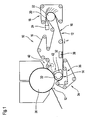
- the formers 10 shown in Figs. 1 to 5 are each part of a machine for the manufacture of a fiber material web which can in particular be a paper web or a card web.
- a pressing zone 14 combined with a suction system is provided in each case.
- a molding press is provided in each of the embodiments of Figs. 4 and 5 .
- the relevant machine includes a former 10 with two circulating dewatering belts 16, 18 which converge while forming a material inlet gap 20 and are subsequently led as an inner belt and as an outer belt respectively over a forming element formed here by a forming roll 22.
- the fiber material suspension is introduced into the material inlet gap 20 by means of a headbox 22.
- the pressing zone 14 combined with a suction system is provided in the web running direction L in front of a nip 30 formed between a dryer cylinder 26, preferably a Yankee cylinder, and a counter element.
- a suction element 32 is provided which, in the present case, is for example a suction roll.
- the fiber material web 12 is supplied together with the inner belt 16 which wraps around the forming roll 22 to the pressing zone 14.
- a further dewatering belt 34 is led around the suction element 32 in addition to the inner belt 16 which is directly supported on it.
- the fiber material web 12 lies here between the inner belt 16 and the further dewatering belt 34.
- a belt 36 tensioned around the suction element 32 is arranged within the loop of the further dewatering belt 34 and can be formed by a customary, in particular non-structured screen, or also by a structured screen.
- TAD Through-Air-Drying
- DSP DSP screen
- Screens of the type which are described in PCT/G99/02684 can, for example, be considered as screens with permeability which differs zone-wise.
- the relevant screens can, in particular, consist of a fabric in which threads extending in a first direction in one plane or in a plurality of planes are interwoven with threads extending in a second direction such that a grid results which separates a plurality of systematically distributed zones of pre-determinable configuration from one another and correspondingly determines them, with the systematically distributed zones each including at least three threads extending in the one direction and at least three threads extending in the other direction.
- the threads can, in particular, be weft threads and warp threads.
- the tension of the belt 36 tensioned around the suction element 32 and arranged within the loop of the further dewatering belt 34 is expediently larger than or equal to 60 kN/m.
- the belt 36 tensioned around the suction element and arranged within the loop of the further dewatering belt 34 can have a smooth or closed surface or also a drilled and/or grooved surface.
- the pressing zone 14 combined with a suction system forms a longitudinal gap extended in the web running direction L.
- the suction element 32 is simultaneously provided as a first counter-element which forms the nip 30 together with the dryer cylinder or the Yankee cylinder 26.
- the outer belt 18 which wraps around the forming roll 22 is formed by a dewatering screen, with the former 10 being provided in the present case as a crescent former of which the outer belt 18 is formed by the dewatering screen and the inner belt 16 is formed by a felt.
- the dry content of the fiber material web 12 in front of the pressing zone 14 preferably lies in a range from about 8 % to about 15 % and after the pressing zone 14 in a range of about 40 % or higher.
- a suction box 38 can be provided between the forming element 22 and the pressing zone 14.
- the dry content of the fiber material web 12 directly after the suction box 38 and before the pressing zone 14 preferably lies in a range of about 23 %.
- a preferably adjustable guide roll 40 for the inner belt 16 which guides the fiber material web 12 with it is provided in the web running direction L after the nip 30.
- the tension of the further dewatering belt 34 can in particular amount to about 5 kN/m.
- the tension of the outer belt 18 amounts preferably to about 8 kN/m.
- the tension of the inner belt 16 can in particular amount to about 5 kN/m.
- a crescent former 10 is thus provided with a dewatering belt or dewatering screen as an outer belt 18 and a felt as an inner belt 16.
- a dewatering belt or dewatering screen as an outer belt 18
- a felt as an inner belt 16.
- the dry content of the fiber material web in front of the pressing zone 14 expediently lies in a range of about 8 % to about 15 % and after the pressing zone 14 preferably in a range of about 40 % or higher.
- a suction box 38 can also be used which helps the press to dry the inner belt 16 formed by the felt and the fiber material web 12 in order to provide additional space within the felt and thus to absorb more water from the structure of the fiber material web 12.
- the dry content of the fiber material web 12 directly after the suction box 38 and in front of the pressing zone 14 preferably lies in a range of about 23 %.
- the belt press provided here operates as follows:
- the fiber material web 12 is basically enclosed in sandwich-like manner between a further dewatering belt 34 formed in particular by a screen and the inner belt 16 which is directly supported on the surface of the suction element, or on the suction roll which supports the inner belt 16.
- the further dewatering belt 34 can be a conventional, in particular non-structured screen or also a structured screen.
- a TAD screen, a dewatering screen with differing screen permeability zone-wise, such as in particular a so-called DSP screen or the like can be provided.
- a belt 36 (fabric or belt) is arranged which is tensioned at a high tension of preferably about 60 kN/m or more and which thus generates a distributed load over the suction element 32, which is, for example, formed here by a suction roll.
- the strongly tensioned belt 36 which is, for example, a fabric belt or can be another belt (fabric or belt), can have a smooth or closed surface or also a drilled and/or grooved surface.
- a further advantage of this arrangement lies in the fact that a pressing zone 14 is provided which is combined with a suction system.
- a shoe pressing unit is associated with the drier cylinder or Yankee cylinder 26 only pressure is generated.
- a suction roll associated with the dryer cylinder or the Yankee cylinder 26 the surface of the dryer cylinder or Yankee cylinder 26 does not permit any air flow through the nip 30 despite the presence of vacuum.
- the suction in the region of the element 32 can in particular take place at least substantially over the entire machine width.
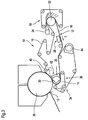
- a double screen former is provided as the former 10, with the inner belt 16 which wraps around the forming elements and the forming roll 22 being formed by a conventional or structured dewatering belt or screen instead of by a felt.
- the tension of this dewatering belt 16 expediently amounts again to about 5 kN/m.
- the suction box 38 here also as a "wet shaping box”. It removes some water from the paper and simultaneously produces cushions on the sheet structure.
- the dry content of the paper lies directly after the wet shaping box and prior to the pressing step preferably at about 20 %. After the press a dry content of about 40 % is expected.
- the further dewatering belt 34 is formed in the present case by a felt, the tension of which expediently amounts again to about 5 kN/m.
- a further suction element 44 is provided for the drying of the further dewatering belt or felt 34.
- this further suction element 44 is only wrapped around by the further dewatering belt 34 or felt.
- This further suction element 44 can in particular also be a suction roll or suction box.
- a suction over at least substantially the full machine width can in particular also take place again here.
- this embodiment in accordance with Fig. 2 can in particular have at least substantially the same construction again as the embodiment of Fig. 1 .
- the same reference numerals are associated with parts which correspond to one another.
- a crescent former with a dewatering belt or dewatering screen as an outer belt and a felt as an inner belt 16 is again provided as the former 10.
- the inner belt 16 In the present case not only the inner belt 16, but also the further dewatering belt 34 is formed by a felt. In the region of the pressing zone 14 combined with a suction system the fiber material web 12 thus lies in sandwich-like manner between two felts.
- An adjustable guide roll 40 for the inner belt 16 can in particular also be provided again.
- this embodiment in accordance with Fig. 3 has in particular at least substantially the same construction again as that of Fig. 2 .
- the same reference numerals are associated with parts which correspond to one another.
- the former 10 is again provided as a crescent former with a dewatering belt or dewatering screen as the outer belt and a felt as the inner belt 16.
- the associated pressing zone 14 combined with a suction system is for example formed here by a molding press.
- a roll 48 is arranged for this purpose within the loop of the further dewatering belt 34 opposite to the suction element 32.
- This roll can have a closed surface or can also be grooved and/or blind-drilled. In the present case it is for example formed by a rigid roll.
- a shoe pressing unit can, for example, also basically be provided instead of such a rigid roll 48. Basically, both a normal gap or a longitudinal gap can also be formed.
- the shoe pressing unit can, for example, be a shoe pressing roll.
- this embodiment in accordance with Fig. 4 can in particular again have at least substantially the same construction as that of Fig. 1 .
- the same reference numerals are associated with parts which correspond to one another.
- a horizontal double screen former with a dewatering screen as the outer belt 18 and a structured or non-structured dewatering belt or screen as the inner belt 16 is again provided as the former 10.
- the pressing zone 14 combined with a suction system is also, for example, again formed in the present case by a molding press.
- a further suction element 44 can be provided for the drying of the dewatering belt or felt 34.
- this further suction element 44 is only wrapped around by the dewatering belt 34 or felt.
- This further suction element 44 can in particular also be a suction roll or suction box.
- a suction over at least substantially the full machine width can in particular also take place again here.
- a vacuum box 50 or the like can be associated with the dewatering belt or felt 34.
- Fig. 5 is distinguished from that of Fig. 4 essentially only in that the further dewatering belt 34 is formed by a felt.
- the same reference numerals are associated with parts which correspond to one another.
Landscapes
- Paper (AREA)
- Spinning Methods And Devices For Manufacturing Artificial Fibers (AREA)
Claims (29)
- Machine de fabrication d'une nappe fibreuse (12), en particulier d'une bande de papier ou de carton, ayant une section de formage incluant un formeur (10) comprenant deux bandes en mouvement d'égouttage sans fin (16, 18) qui convergent en formant une fente d'entrée de matériau (20) et qui sont ensuite amenées sous forme d'une bande interne et une bande externe respectivement sur un élément de formage (22), comme en particulier un rouleau de formage, et au moins une section de pressage (14) combinée à un système d'aspiration et prévue dans la direction d'avance de la nappe (L) devant un pinçage (30) formé entre un cylindre de séchage (26), de préférence un cylindre Yankee, et un premier élément conjugué, ladite section de pressage (14) étant disposée devant ledit cylindre de séchage et étant formée entre un élément aspirant (32) et un deuxième élément conjugué (38, 48), ladite nappe fibreuse (12) étant guidée à travers ladite section de pressage (14) et à travers ledit pinçage (30) conjointement avec ladite bande interne (16), une bande d'égouttage sans fin supplémentaire (34) étant guidée autour de l'élément aspirant (32) en plus de la bande interne (16), la nappe fibreuse (12) étant disposée entre la bande interne (16) et la bande d'égouttage supplémentaire (34),
caractérisée en ce que
ledit élément aspirant (32) est simultanément prévu en tant que premier élément conjugué, en ce que ladite bande d'égouttage interne (16) est directement supportée sur la surface dudit élément aspirant (32), et
en ce que ledit deuxième élément conjugué (36, 48) est disposé dans la boucle de ladite bande d'égouttage supplémentaire (34) et est formé par une bande (36) tendue autour de l'élément aspirant (32), par un rouleau (48) disposé en regard de l'élément aspirant (32), ou par une unité de presse à sabot située en regard de l'élément aspirant (32). - Machine selon la revendication 1, caractérisée en ce que l'élément aspirant (32) comprend un rouleau aspirant.
- Machine selon la revendication 1 ou 2, caractérisée en ce que le deuxième élément conjugué est une bande (36) tendue autour de l'élément aspirant (32), la tension de ladite bande (36) étant supérieure ou égale à 60 kN/m.
- Machine selon l'une quelconque des revendications précédentes, caractérisée en ce que ledit deuxième élément conjugué est une bande (36) tendue autour de l'élément aspirant (32), ladite bande (36) ayant une surface lisse.
- Machine selon l'une quelconque des revendications 1 à 3, caractérisée en ce que le deuxième élément conjugué est une bande (36) tendue autour de l'élément aspirant (32), ladite bande (36) ayant une surface perforée et/ou rainurée.
- Machine selon l'une quelconque des revendications précédentes, caractérisée en ce que la section de pressage (14) forme une fente qui s'étend dans la direction d'avance de la nappe et à travers laquelle passe la nappe.
- Machine selon la revendication 1 ou 2, caractérisée en ce que le deuxième élément conjugué est un rouleau (48) disposé en regard de l'élément aspirant (32), ledit rouleau ayant une surface fermée.
- Machine selon la revendication 1 ou 2, caractérisée en ce que le deuxième élément conjugué est un rouleau (48) situé en regard de l'élément aspirant (32), ledit rouleau étant rainuré et/ou pourvu de trous borgnes.
- Machine selon la revendication 1, 2, 7 ou 8, caractérisée en ce que le deuxième élément conjugué est un rouleau rigide (48) situé en regard de l'élément aspirant (32).
- Machine selon la revendication 1 ou 2, caractérisée en ce que le deuxième élément conjugué est une unité de presse à sabot située en regard de l'élément aspirant, ladite unité de presse à sabot comprenant un rouleau de pressage à sabot.
- Machine selon l'une quelconque des revendications précédentes, caractérisée en ce que la bande externe (18) est formée par une toile d'égouttage.
- Machine selon la revendication 11, caractérisée en ce que le formeur (10) est prévu sous forme de formeur en croissant dont la bande interne (16) est formée d'un feutre.
- Machine selon la revendication 11, caractérisée en ce que le formeur (10) est prévu sous forme de formeur double toile.
- Machine selon la revendication 12 ou 13, caractérisée en ce que la bande d'égouttage supplémentaire (34) est formée par un feutre.
- Machine selon l'une quelconque des revendications 1 à 13, caractérisée en ce que la bande d'égouttage supplémentaire (34) est formée par une toile non structurée.
- Machine selon l'une quelconque des revendications 1 à 13, caractérisée en ce que la bande d'égouttage supplémentaire (34) est formée par une toile structurée.
- Machine selon l'une quelconque des revendications 1 à 13, caractérisée en ce que la bande d'égouttage supplémentaire (34) est formée par une toile TAD (TAD = through-air-drying, séchage par soufflage transversal).
- Machine selon l'une quelconque des revendications 1 à 13, caractérisée en ce que la bande d'égouttage supplémentaire (34) est formée par une toile d'égouttage avec une perméabilité différente de la toile en fonction des sections.
- Machine selon l'une quelconque des revendications précédentes, caractérisée en ce que la teneur en matières sèches de la nappe fibreuse (12) avant la section de pressage (14) est de l'ordre d'environ 8 à environ 15% et, après la section de pressage (14), de l'ordre d'environ 40% ou plus.
- Machine selon l'une quelconque des revendications 1 à 18, caractérisée en ce qu'une caisse aspirante (38) est prévue entre l'élément de formage (22) et la section de pressage (14).
- Machine selon la revendication 20, caractérisée en ce que la teneur en matières sèches de la nappe fibreuse (12) directement après la caisse aspirante (38) et avant la section de pressage (14) est de l'ordre d'environ 23 %.
- Machine selon l'une quelconque des revendications précédentes, caractérisée en ce qu'un rouleau de guidage (40) pour la bande interne (16), qui déplace la nappe fibreuse (12) avec lui, est prévu dans la direction d'avance de la nappe (L) après le pinçage (30) et est en particulier un rouleau de guidage ajustable.
- Machine selon l'une quelconque des revendications précédentes, caractérisée en ce que la tension de la bande d'égouttage supplémentaire (34) est d'environ 5 kN/m.
- Machine selon l'une quelconque des revendications précédentes, caractérisée en ce que la tension de la bande externe (18) est d'environ 8 kN/m.
- Machine selon l'une quelconque des revendications précédentes, caractérisée en ce que la tension de la bande interne (16) est d'environ 5 kN/m.
- Machine selon l'une quelconque des revendications précédentes, caractérisée en ce qu'un élément aspirant supplémentaire (44) est prévu dans la boucle de la bande d'égouttage supplémentaire (34).
- Machine selon la revendication 26, caractérisée en ce que l'élément aspirant supplémentaire (44) est uniquement entouré par la bande d'égouttage supplémentaire (34).
- Machine selon la revendication 26 ou 27, caractérisée en ce que l'élément aspirant supplémentaire (44) est formé par un rouleau aspirant.
- Machine selon la revendication 26 ou 27, caractérisée en ce que l'élément aspirant supplémentaire (44) est formé par une caisse aspirante.
Priority Applications (5)
| Application Number | Priority Date | Filing Date | Title |
|---|---|---|---|
| EP03021859A EP1518960B1 (fr) | 2003-09-26 | 2003-09-26 | Machine pour fabriquer une bande de matière fibreuse |
| DE60321573T DE60321573D1 (de) | 2003-09-26 | 2003-09-26 | Maschine zur Herstellung einer Faserstoffbahn |
| AT03021859T ATE398207T1 (de) | 2003-09-26 | 2003-09-26 | Maschine zur herstellung einer faserstoffbahn |
| PCT/EP2004/052224 WO2005031065A1 (fr) | 2003-09-26 | 2004-09-17 | Machine de fabrication d'une bande de matiere fibreuse |
| US10/573,110 US7615136B2 (en) | 2003-09-26 | 2004-09-17 | Machine for the manufacture of a fiber material web |
Applications Claiming Priority (1)
| Application Number | Priority Date | Filing Date | Title |
|---|---|---|---|
| EP03021859A EP1518960B1 (fr) | 2003-09-26 | 2003-09-26 | Machine pour fabriquer une bande de matière fibreuse |
Publications (2)
| Publication Number | Publication Date |
|---|---|
| EP1518960A1 EP1518960A1 (fr) | 2005-03-30 |
| EP1518960B1 true EP1518960B1 (fr) | 2008-06-11 |
Family
ID=34178511
Family Applications (1)
| Application Number | Title | Priority Date | Filing Date |
|---|---|---|---|
| EP03021859A Expired - Lifetime EP1518960B1 (fr) | 2003-09-26 | 2003-09-26 | Machine pour fabriquer une bande de matière fibreuse |
Country Status (5)
| Country | Link |
|---|---|
| US (1) | US7615136B2 (fr) |
| EP (1) | EP1518960B1 (fr) |
| AT (1) | ATE398207T1 (fr) |
| DE (1) | DE60321573D1 (fr) |
| WO (1) | WO2005031065A1 (fr) |
Cited By (2)
| Publication number | Priority date | Publication date | Assignee | Title |
|---|---|---|---|---|
| US8075739B2 (en) | 2004-10-26 | 2011-12-13 | Voith Patent Gmbh | Advanced dewatering system |
| CN103987893A (zh) * | 2011-12-08 | 2014-08-13 | 福伊特专利公司 | 用于制造薄纸的机器 |
Families Citing this family (25)
| Publication number | Priority date | Publication date | Assignee | Title |
|---|---|---|---|---|
| US7351307B2 (en) * | 2004-01-30 | 2008-04-01 | Voith Paper Patent Gmbh | Method of dewatering a fibrous web with a press belt |
| US7476294B2 (en) | 2004-10-26 | 2009-01-13 | Voith Patent Gmbh | Press section and permeable belt in a paper machine |
| US7476293B2 (en) | 2004-10-26 | 2009-01-13 | Voith Patent Gmbh | Advanced dewatering system |
| DE102005036891A1 (de) | 2005-08-05 | 2007-02-08 | Voith Patent Gmbh | Maschine zur Herstellung von Tissuepapier |
| US7527709B2 (en) | 2006-03-14 | 2009-05-05 | Voith Paper Patent Gmbh | High tension permeable belt for an ATMOS system and press section of paper machine using the permeable belt |
| EP1845187A3 (fr) | 2006-04-14 | 2013-03-06 | Voith Patent GmbH | Formeur à deux toiles de système ATMOS |
| US7524403B2 (en) | 2006-04-28 | 2009-04-28 | Voith Paper Patent Gmbh | Forming fabric and/or tissue molding belt and/or molding belt for use on an ATMOS system |
| US7550061B2 (en) | 2006-04-28 | 2009-06-23 | Voith Paper Patent Gmbh | Dewatering tissue press fabric for an ATMOS system and press section of a paper machine using the dewatering fabric |
| FI20075452L (fi) * | 2007-06-15 | 2008-12-16 | Upm Kymmene Corp | Menetelmä ja laitteisto paperin valmistamiseksi |
| US20090038174A1 (en) * | 2007-08-07 | 2009-02-12 | Dar-Style Consultants & More Ltd. | Kitchen utensil dryer |
| AT505760B1 (de) * | 2008-01-09 | 2009-04-15 | Andritz Ag Maschf | Vorrichtung und verfahren zur entwasserung einer materialbahn |
| DE102008000211A1 (de) * | 2008-02-01 | 2009-08-06 | Voith Patent Gmbh | Vorrichtung zur Herstellung von Tissuebahnen |
| JP5716378B2 (ja) * | 2010-12-17 | 2015-05-13 | 王子ホールディングス株式会社 | 繊維シートの製造装置 |
| DE102011007568A1 (de) | 2011-04-18 | 2012-10-18 | Voith Patent Gmbh | Vorrichtung und Verfahren zur Herstellung einer Materialbahn |
| DE102011087986A1 (de) | 2011-12-08 | 2013-06-13 | Voith Patent Gmbh | Maschine zur Herstellung von faserhaltigem Bahnenmaterial, insbesondere Tissue-Papier |
| DE102011087983A1 (de) | 2011-12-08 | 2013-06-13 | Voith Patent Gmbh | Maschine zur Herstellung von faserhaltigem Bahnenmaterial, insbesondere Tissue-Papier |
| WO2015000684A1 (fr) * | 2013-07-04 | 2015-01-08 | Voith Patent Gmbh | Procédé et dispositif de fabrication de non-tissé |
| EP3017104B1 (fr) * | 2013-07-04 | 2020-03-04 | Voith Patent GmbH | Procédé de conversion et d'utilisation d'un dispositif de fabrication de tissu non-tissé |
| WO2015000690A1 (fr) * | 2013-07-04 | 2015-01-08 | Voith Patent Gmbh | Procédé et dispositif compact de fabrication de non-tissé |
| WO2015000685A1 (fr) * | 2013-07-04 | 2015-01-08 | Voith Patent Gmbh | Procédé et dispositif de fabrication de non-tissé |
| ES2959239T3 (es) * | 2016-02-08 | 2024-02-22 | Gpcp Ip Holdings Llc | Rodillo de moldeo para fabricación de productos de papel |
| KR20180107247A (ko) * | 2016-02-08 | 2018-10-01 | 쥐피씨피 아이피 홀딩스 엘엘씨 | 성형 롤을 이용한 종이 제품의 제조 방법 |
| FI3414393T3 (fi) * | 2016-02-08 | 2023-08-31 | Gpcp Ip Holdings Llc | Paperituotteiden valmistusmenetelmät, joissa käytetään muovaustelaa |
| EP3754081A1 (fr) | 2019-06-18 | 2020-12-23 | SICAM - S.R.L. Societa' Italiana Costruzioni Aeromeccaniche | Section de déshydratation d'un appareil d'hydroenchevêtrement pour la production de tissus non tissés |
| US12404634B2 (en) | 2020-12-07 | 2025-09-02 | Voith Patent Gmbh | Device and method for producing a fibrous web |
Family Cites Families (8)
| Publication number | Priority date | Publication date | Assignee | Title |
|---|---|---|---|---|
| DE1761505C3 (de) * | 1968-05-29 | 1973-09-20 | Kimberly-Clark Corp., Neenah, Wis. (V.St.A.) | Papiermaschine |
| US4139410A (en) * | 1976-06-09 | 1979-02-13 | Olli Tapio | Method of dewatering and drying in a Yankee machine |
| FI770610A7 (fi) * | 1977-02-24 | 1978-08-25 | Valmet Oy | Tissuepappersmaskin |
| DE19654198A1 (de) * | 1996-12-23 | 1998-06-25 | Voith Sulzer Papiermasch Gmbh | Maschine zur Herstellung einer Faserstoffbahn |
| SE511485C2 (sv) * | 1998-02-04 | 1999-10-04 | Valmet Karlstad Ab | Pappersmaskin och förfarande för framställning av en papppersbana |
| SE511736C2 (sv) * | 1998-03-20 | 1999-11-15 | Nordiskafilt Ab Albany | Präglingsband för en pappersmaskin |
| DE19902139A1 (de) * | 1999-01-20 | 2000-07-27 | Voith Sulzer Papiertech Patent | Pressenanordnung |
| US7150110B2 (en) * | 2002-01-24 | 2006-12-19 | Voith Paper Patent Gmbh | Method and an apparatus for manufacturing a fiber web provided with a three-dimensional surface structure |
-
2003
- 2003-09-26 AT AT03021859T patent/ATE398207T1/de active
- 2003-09-26 DE DE60321573T patent/DE60321573D1/de not_active Expired - Lifetime
- 2003-09-26 EP EP03021859A patent/EP1518960B1/fr not_active Expired - Lifetime
-
2004
- 2004-09-17 US US10/573,110 patent/US7615136B2/en not_active Expired - Fee Related
- 2004-09-17 WO PCT/EP2004/052224 patent/WO2005031065A1/fr not_active Ceased
Cited By (3)
| Publication number | Priority date | Publication date | Assignee | Title |
|---|---|---|---|---|
| US8075739B2 (en) | 2004-10-26 | 2011-12-13 | Voith Patent Gmbh | Advanced dewatering system |
| CN103987893A (zh) * | 2011-12-08 | 2014-08-13 | 福伊特专利公司 | 用于制造薄纸的机器 |
| CN103987893B (zh) * | 2011-12-08 | 2016-01-20 | 福伊特专利公司 | 用于制造薄纸的机器和压带 |
Also Published As
| Publication number | Publication date |
|---|---|
| US7615136B2 (en) | 2009-11-10 |
| US20070068645A1 (en) | 2007-03-29 |
| DE60321573D1 (de) | 2008-07-24 |
| ATE398207T1 (de) | 2008-07-15 |
| EP1518960A1 (fr) | 2005-03-30 |
| WO2005031065A1 (fr) | 2005-04-07 |
Similar Documents
| Publication | Publication Date | Title |
|---|---|---|
| EP1518960B1 (fr) | Machine pour fabriquer une bande de matière fibreuse | |
| US7428786B2 (en) | Method and an apparatus for manufacturing a fiber web provided with a three-dimensional surface structure | |
| US7291249B2 (en) | Apparatus for the manufacture of a structured fiber web | |
| CN102021856B (zh) | 高级脱水体系 | |
| CN101914864B (zh) | 造纸机中的压榨段和渗透性带 | |
| US8303773B2 (en) | Machine for the production of tissue paper | |
| US8092652B2 (en) | Advanced dewatering system | |
| US7959764B2 (en) | Forming fabrics for fiber webs | |
| US9347180B2 (en) | Device and method for producing a material web | |
| AU1897999A (en) | Woven fabric | |
| CN107148500B (zh) | 用于纤维材料幅脱水的装置 | |
| US7288168B2 (en) | Machine and method for the manufacture of a fiber material web | |
| CA2451503C (fr) | Methode et machine pour la fabrication d'une voile de carde | |
| US6221214B1 (en) | Wet press and method for treating a fibrous material web | |
| CA2332710A1 (fr) | Machine et procede de fabrication de papier mousseline en feuille continue | |
| US20030062141A1 (en) | Machine for manufacturing a paper of cardboard web and press section therein | |
| CA2804938A1 (fr) | Systeme de deshydratation avance |
Legal Events
| Date | Code | Title | Description |
|---|---|---|---|
| PUAI | Public reference made under article 153(3) epc to a published international application that has entered the european phase |
Free format text: ORIGINAL CODE: 0009012 |
|
| AK | Designated contracting states |
Kind code of ref document: A1 Designated state(s): AT BE BG CH CY CZ DE DK EE ES FI FR GB GR HU IE IT LI LU MC NL PT RO SE SI SK TR |
|
| AX | Request for extension of the european patent |
Extension state: AL LT LV MK |
|
| 17P | Request for examination filed |
Effective date: 20050620 |
|
| AKX | Designation fees paid |
Designated state(s): AT BE BG CH CY CZ DE DK EE ES FI FR GB GR HU IE IT LI LU MC NL PT RO SE SI SK TR |
|
| RAP1 | Party data changed (applicant data changed or rights of an application transferred) |
Owner name: VOITH PATENT GMBH |
|
| 17Q | First examination report despatched |
Effective date: 20060113 |
|
| GRAP | Despatch of communication of intention to grant a patent |
Free format text: ORIGINAL CODE: EPIDOSNIGR1 |
|
| GRAS | Grant fee paid |
Free format text: ORIGINAL CODE: EPIDOSNIGR3 |
|
| GRAA | (expected) grant |
Free format text: ORIGINAL CODE: 0009210 |
|
| AK | Designated contracting states |
Kind code of ref document: B1 Designated state(s): AT BE BG CH CY CZ DE DK EE ES FI FR GB GR HU IE IT LI LU MC NL PT RO SE SI SK TR |
|
| REG | Reference to a national code |
Ref country code: GB Ref legal event code: FG4D |
|
| REG | Reference to a national code |
Ref country code: CH Ref legal event code: EP |
|
| REF | Corresponds to: |
Ref document number: 60321573 Country of ref document: DE Date of ref document: 20080724 Kind code of ref document: P |
|
| REG | Reference to a national code |
Ref country code: IE Ref legal event code: FG4D |
|
| REG | Reference to a national code |
Ref country code: SE Ref legal event code: TRGR |
|
| PG25 | Lapsed in a contracting state [announced via postgrant information from national office to epo] |
Ref country code: SI Free format text: LAPSE BECAUSE OF FAILURE TO SUBMIT A TRANSLATION OF THE DESCRIPTION OR TO PAY THE FEE WITHIN THE PRESCRIBED TIME-LIMIT Effective date: 20080611 |
|
| PG25 | Lapsed in a contracting state [announced via postgrant information from national office to epo] |
Ref country code: NL Free format text: LAPSE BECAUSE OF FAILURE TO SUBMIT A TRANSLATION OF THE DESCRIPTION OR TO PAY THE FEE WITHIN THE PRESCRIBED TIME-LIMIT Effective date: 20080611 |
|
| NLV1 | Nl: lapsed or annulled due to failure to fulfill the requirements of art. 29p and 29m of the patents act | ||
| PG25 | Lapsed in a contracting state [announced via postgrant information from national office to epo] |
Ref country code: PT Free format text: LAPSE BECAUSE OF FAILURE TO SUBMIT A TRANSLATION OF THE DESCRIPTION OR TO PAY THE FEE WITHIN THE PRESCRIBED TIME-LIMIT Effective date: 20081111 Ref country code: CZ Free format text: LAPSE BECAUSE OF FAILURE TO SUBMIT A TRANSLATION OF THE DESCRIPTION OR TO PAY THE FEE WITHIN THE PRESCRIBED TIME-LIMIT Effective date: 20080611 Ref country code: ES Free format text: LAPSE BECAUSE OF FAILURE TO SUBMIT A TRANSLATION OF THE DESCRIPTION OR TO PAY THE FEE WITHIN THE PRESCRIBED TIME-LIMIT Effective date: 20080922 |
|
| PG25 | Lapsed in a contracting state [announced via postgrant information from national office to epo] |
Ref country code: RO Free format text: LAPSE BECAUSE OF FAILURE TO SUBMIT A TRANSLATION OF THE DESCRIPTION OR TO PAY THE FEE WITHIN THE PRESCRIBED TIME-LIMIT Effective date: 20080611 Ref country code: BE Free format text: LAPSE BECAUSE OF FAILURE TO SUBMIT A TRANSLATION OF THE DESCRIPTION OR TO PAY THE FEE WITHIN THE PRESCRIBED TIME-LIMIT Effective date: 20080611 Ref country code: SK Free format text: LAPSE BECAUSE OF FAILURE TO SUBMIT A TRANSLATION OF THE DESCRIPTION OR TO PAY THE FEE WITHIN THE PRESCRIBED TIME-LIMIT Effective date: 20080611 |
|
| PLBE | No opposition filed within time limit |
Free format text: ORIGINAL CODE: 0009261 |
|
| STAA | Information on the status of an ep patent application or granted ep patent |
Free format text: STATUS: NO OPPOSITION FILED WITHIN TIME LIMIT |
|
| PG25 | Lapsed in a contracting state [announced via postgrant information from national office to epo] |
Ref country code: BG Free format text: LAPSE BECAUSE OF FAILURE TO SUBMIT A TRANSLATION OF THE DESCRIPTION OR TO PAY THE FEE WITHIN THE PRESCRIBED TIME-LIMIT Effective date: 20080911 Ref country code: DK Free format text: LAPSE BECAUSE OF FAILURE TO SUBMIT A TRANSLATION OF THE DESCRIPTION OR TO PAY THE FEE WITHIN THE PRESCRIBED TIME-LIMIT Effective date: 20080611 Ref country code: MC Free format text: LAPSE BECAUSE OF NON-PAYMENT OF DUE FEES Effective date: 20080930 Ref country code: EE Free format text: LAPSE BECAUSE OF FAILURE TO SUBMIT A TRANSLATION OF THE DESCRIPTION OR TO PAY THE FEE WITHIN THE PRESCRIBED TIME-LIMIT Effective date: 20080611 |
|
| REG | Reference to a national code |
Ref country code: CH Ref legal event code: PL |
|
| 26N | No opposition filed |
Effective date: 20090312 |
|
| GBPC | Gb: european patent ceased through non-payment of renewal fee |
Effective date: 20080926 |
|
| REG | Reference to a national code |
Ref country code: FR Ref legal event code: ST Effective date: 20090529 |
|
| PG25 | Lapsed in a contracting state [announced via postgrant information from national office to epo] |
Ref country code: IE Free format text: LAPSE BECAUSE OF NON-PAYMENT OF DUE FEES Effective date: 20080926 |
|
| PG25 | Lapsed in a contracting state [announced via postgrant information from national office to epo] |
Ref country code: LI Free format text: LAPSE BECAUSE OF NON-PAYMENT OF DUE FEES Effective date: 20080930 Ref country code: FR Free format text: LAPSE BECAUSE OF NON-PAYMENT OF DUE FEES Effective date: 20080930 Ref country code: CH Free format text: LAPSE BECAUSE OF NON-PAYMENT OF DUE FEES Effective date: 20080930 |
|
| PG25 | Lapsed in a contracting state [announced via postgrant information from national office to epo] |
Ref country code: GB Free format text: LAPSE BECAUSE OF NON-PAYMENT OF DUE FEES Effective date: 20080926 |
|
| PG25 | Lapsed in a contracting state [announced via postgrant information from national office to epo] |
Ref country code: LU Free format text: LAPSE BECAUSE OF NON-PAYMENT OF DUE FEES Effective date: 20080926 Ref country code: HU Free format text: LAPSE BECAUSE OF FAILURE TO SUBMIT A TRANSLATION OF THE DESCRIPTION OR TO PAY THE FEE WITHIN THE PRESCRIBED TIME-LIMIT Effective date: 20081212 Ref country code: CY Free format text: LAPSE BECAUSE OF FAILURE TO SUBMIT A TRANSLATION OF THE DESCRIPTION OR TO PAY THE FEE WITHIN THE PRESCRIBED TIME-LIMIT Effective date: 20080611 |
|
| PG25 | Lapsed in a contracting state [announced via postgrant information from national office to epo] |
Ref country code: TR Free format text: LAPSE BECAUSE OF FAILURE TO SUBMIT A TRANSLATION OF THE DESCRIPTION OR TO PAY THE FEE WITHIN THE PRESCRIBED TIME-LIMIT Effective date: 20080611 |
|
| PG25 | Lapsed in a contracting state [announced via postgrant information from national office to epo] |
Ref country code: GR Free format text: LAPSE BECAUSE OF FAILURE TO SUBMIT A TRANSLATION OF THE DESCRIPTION OR TO PAY THE FEE WITHIN THE PRESCRIBED TIME-LIMIT Effective date: 20080912 |
|
| PGFP | Annual fee paid to national office [announced via postgrant information from national office to epo] |
Ref country code: FI Payment date: 20150911 Year of fee payment: 13 |
|
| PG25 | Lapsed in a contracting state [announced via postgrant information from national office to epo] |
Ref country code: FI Free format text: LAPSE BECAUSE OF NON-PAYMENT OF DUE FEES Effective date: 20160926 |
|
| PGFP | Annual fee paid to national office [announced via postgrant information from national office to epo] |
Ref country code: DE Payment date: 20200925 Year of fee payment: 18 |
|
| REG | Reference to a national code |
Ref country code: DE Ref legal event code: R119 Ref document number: 60321573 Country of ref document: DE |
|
| PG25 | Lapsed in a contracting state [announced via postgrant information from national office to epo] |
Ref country code: DE Free format text: LAPSE BECAUSE OF NON-PAYMENT OF DUE FEES Effective date: 20220401 |
|
| PGFP | Annual fee paid to national office [announced via postgrant information from national office to epo] |
Ref country code: SE Payment date: 20220920 Year of fee payment: 20 Ref country code: AT Payment date: 20220921 Year of fee payment: 20 |
|
| PGFP | Annual fee paid to national office [announced via postgrant information from national office to epo] |
Ref country code: IT Payment date: 20220926 Year of fee payment: 20 |
|
| REG | Reference to a national code |
Ref country code: SE Ref legal event code: EUG |
|
| REG | Reference to a national code |
Ref country code: AT Ref legal event code: MK07 Ref document number: 398207 Country of ref document: AT Kind code of ref document: T Effective date: 20230926 |