EP1519025A2 - Méthode et appareil d'exploitation d'un moteur à combustion - Google Patents
Méthode et appareil d'exploitation d'un moteur à combustion Download PDFInfo
- Publication number
- EP1519025A2 EP1519025A2 EP04018896A EP04018896A EP1519025A2 EP 1519025 A2 EP1519025 A2 EP 1519025A2 EP 04018896 A EP04018896 A EP 04018896A EP 04018896 A EP04018896 A EP 04018896A EP 1519025 A2 EP1519025 A2 EP 1519025A2
- Authority
- EP
- European Patent Office
- Prior art keywords
- actuators
- energy consumption
- actuator
- energy
- cyl
- Prior art date
- Legal status (The legal status is an assumption and is not a legal conclusion. Google has not performed a legal analysis and makes no representation as to the accuracy of the status listed.)
- Granted
Links
Images


Classifications
-
- F—MECHANICAL ENGINEERING; LIGHTING; HEATING; WEAPONS; BLASTING
- F02—COMBUSTION ENGINES; HOT-GAS OR COMBUSTION-PRODUCT ENGINE PLANTS
- F02D—CONTROLLING COMBUSTION ENGINES
- F02D41/00—Electrical control of supply of combustible mixture or its constituents
- F02D41/20—Output circuits, e.g. for controlling currents in command coils
- F02D41/2096—Output circuits, e.g. for controlling currents in command coils for controlling piezoelectric injectors
-
- F—MECHANICAL ENGINEERING; LIGHTING; HEATING; WEAPONS; BLASTING
- F02—COMBUSTION ENGINES; HOT-GAS OR COMBUSTION-PRODUCT ENGINE PLANTS
- F02D—CONTROLLING COMBUSTION ENGINES
- F02D41/00—Electrical control of supply of combustible mixture or its constituents
- F02D41/22—Safety or indicating devices for abnormal conditions
- F02D41/221—Safety or indicating devices for abnormal conditions relating to the failure of actuators or electrically driven elements
-
- F—MECHANICAL ENGINEERING; LIGHTING; HEATING; WEAPONS; BLASTING
- F02—COMBUSTION ENGINES; HOT-GAS OR COMBUSTION-PRODUCT ENGINE PLANTS
- F02D—CONTROLLING COMBUSTION ENGINES
- F02D41/00—Electrical control of supply of combustible mixture or its constituents
- F02D41/20—Output circuits, e.g. for controlling currents in command coils
- F02D2041/2003—Output circuits, e.g. for controlling currents in command coils using means for creating a boost voltage, i.e. generation or use of a voltage higher than the battery voltage, e.g. to speed up injector opening
-
- F—MECHANICAL ENGINEERING; LIGHTING; HEATING; WEAPONS; BLASTING
- F02—COMBUSTION ENGINES; HOT-GAS OR COMBUSTION-PRODUCT ENGINE PLANTS
- F02D—CONTROLLING COMBUSTION ENGINES
- F02D41/00—Electrical control of supply of combustible mixture or its constituents
- F02D41/20—Output circuits, e.g. for controlling currents in command coils
- F02D2041/202—Output circuits, e.g. for controlling currents in command coils characterised by the control of the circuit
- F02D2041/2048—Output circuits, e.g. for controlling currents in command coils characterised by the control of the circuit said control involving a limitation, e.g. applying current or voltage limits
-
- F—MECHANICAL ENGINEERING; LIGHTING; HEATING; WEAPONS; BLASTING
- F02—COMBUSTION ENGINES; HOT-GAS OR COMBUSTION-PRODUCT ENGINE PLANTS
- F02D—CONTROLLING COMBUSTION ENGINES
- F02D41/00—Electrical control of supply of combustible mixture or its constituents
- F02D41/20—Output circuits, e.g. for controlling currents in command coils
- F02D2041/202—Output circuits, e.g. for controlling currents in command coils characterised by the control of the circuit
- F02D2041/2051—Output circuits, e.g. for controlling currents in command coils characterised by the control of the circuit using voltage control
-
- F—MECHANICAL ENGINEERING; LIGHTING; HEATING; WEAPONS; BLASTING
- F02—COMBUSTION ENGINES; HOT-GAS OR COMBUSTION-PRODUCT ENGINE PLANTS
- F02D—CONTROLLING COMBUSTION ENGINES
- F02D41/00—Electrical control of supply of combustible mixture or its constituents
- F02D41/20—Output circuits, e.g. for controlling currents in command coils
- F02D2041/202—Output circuits, e.g. for controlling currents in command coils characterised by the control of the circuit
- F02D2041/2058—Output circuits, e.g. for controlling currents in command coils characterised by the control of the circuit using information of the actual current value
-
- F—MECHANICAL ENGINEERING; LIGHTING; HEATING; WEAPONS; BLASTING
- F02—COMBUSTION ENGINES; HOT-GAS OR COMBUSTION-PRODUCT ENGINE PLANTS
- F02D—CONTROLLING COMBUSTION ENGINES
- F02D41/00—Electrical control of supply of combustible mixture or its constituents
- F02D41/20—Output circuits, e.g. for controlling currents in command coils
- F02D2041/2068—Output circuits, e.g. for controlling currents in command coils characterised by the circuit design or special circuit elements
- F02D2041/2082—Output circuits, e.g. for controlling currents in command coils characterised by the circuit design or special circuit elements the circuit being adapted to distribute current between different actuators or recuperate energy from actuators
-
- F—MECHANICAL ENGINEERING; LIGHTING; HEATING; WEAPONS; BLASTING
- F02—COMBUSTION ENGINES; HOT-GAS OR COMBUSTION-PRODUCT ENGINE PLANTS
- F02D—CONTROLLING COMBUSTION ENGINES
- F02D2400/00—Control systems adapted for specific engine types; Special features of engine control systems not otherwise provided for; Power supply, connectors or cabling for engine control systems
- F02D2400/14—Power supply for engine control systems
-
- F—MECHANICAL ENGINEERING; LIGHTING; HEATING; WEAPONS; BLASTING
- F02—COMBUSTION ENGINES; HOT-GAS OR COMBUSTION-PRODUCT ENGINE PLANTS
- F02D—CONTROLLING COMBUSTION ENGINES
- F02D41/00—Electrical control of supply of combustible mixture or its constituents
- F02D41/02—Circuit arrangements for generating control signals
- F02D41/14—Introducing closed-loop corrections
- F02D41/1438—Introducing closed-loop corrections using means for determining characteristics of the combustion gases; Sensors therefor
- F02D41/1477—Introducing closed-loop corrections using means for determining characteristics of the combustion gases; Sensors therefor characterised by the regulation circuit or part of it,(e.g. comparator, PI regulator, output)
- F02D41/1479—Using a comparator with variable reference
-
- H—ELECTRICITY
- H03—ELECTRONIC CIRCUITRY
- H03K—PULSE TECHNIQUE
- H03K17/00—Electronic switching or gating, i.e. not by contact-making and –breaking
- H03K17/08—Modifications for protecting switching circuit against overcurrent or overvoltage
- H03K17/082—Modifications for protecting switching circuit against overcurrent or overvoltage by feedback from the output to the control circuit
-
- H—ELECTRICITY
- H10—SEMICONDUCTOR DEVICES; ELECTRIC SOLID-STATE DEVICES NOT OTHERWISE PROVIDED FOR
- H10N—ELECTRIC SOLID-STATE DEVICES NOT OTHERWISE PROVIDED FOR
- H10N30/00—Piezoelectric or electrostrictive devices
- H10N30/80—Constructional details
- H10N30/802—Circuitry or processes for operating piezoelectric or electrostrictive devices not otherwise provided for, e.g. drive circuits
Definitions
- the invention relates to a method for operating an internal combustion engine with n cyl cylinders, which are individually controlled by a control unit via preferably in each case an associated actuator.
- the invention relates to a computer program and a device for carrying out this method, as well as a data carrier with such a computer program.
- EP 1 139 444 is known in the art A1 an injection system for an internal combustion engine as well a method for controlling the same known.
- the Injection system includes piezo actuators for controlling the in the cylinders of the internal combustion engine respectively injected Fuel quantity.
- the injection system includes a drive circuit for driving the piezo actuators, being between the drive circuit and the piezo actuators a buffer capacitor is connected.
- the said known application suggests the voltage drop over the buffer capacitor and / or the charge of the Buffer capacitor to monitor in case of a Drop of this buffer voltage below a given Threshold is detected, to an error, especially with the piezo actuators, infer to can.
- the control unit and in particular the DC-DC converter contained therein is designed so that it is secondary if possible, each required by the actuators performance provides. This is traditionally done in such a way that if a drop in voltage across the buffer capacitor to Example due to increased power consumption by the actuators is detected by the DC / DC converter provided power is increased; possibly also beyond the nominal output power of the converter.
- One such increased power consumption by the actuators can on the one hand by component tolerances or by Aging effects on the actuators be conditional.
- the so far carried out uncontrolled increase of the converter However, provided performance may cause the converter due to the resulting Power loss is overheated and destroyed.
- This object is achieved by that in the patent claim 1 claimed method solved.
- This procedure is thereby characterized in that of preferably all the actuators of Internal combustion engine total consumed middle electrical power is detected that this detected average electric power with a given Nominal nominal power of the control unit is compared and that of the actuators in the future overall consumed electrical power is reduced when the Comparison shows that the detected mean electrical Power is greater than the specified target power, which can be issued by the control unit to the actuators Rated power represents.
- “recorded power” means recorded by an actor during a charge Power.
- the term “delivered Power” from an actuator during a discharge released electrical power.
- the term “consumed electric power or energy” the difference between absorbed and delivered electrical power or energy.
- Essential to the invention basically the consumed electrical power or the consumed electrical energy, because this at least on average by the control unit 120th or the one of the converter device 122 represents electrical power to be provided.
- This claimed method offers the advantage that a Thermal destruction of the control unit or the located therein DC / DC converter due to proposal for a regulation to be made available by it electrical power is avoided. This will be automatically also avoided a car in which this Procedure is implemented due to a failure of this Converter remains in the field and that subsequently a Replacement of the control unit must be made.
- to Calculation of these energy uses will be that of each single actuator during a charging process for a Injection absorbed energy and that of the actuator delivered during a subsequent unloading Energy determined; this results in a measured Energy consumption per actuator.
- the internal combustion engine from the measured Energy consumption of the individual actuators become two Embodiments described, wherein the calculation according to the first embodiment in dependence of each current operating point of the internal combustion engine and the calculation according to the second embodiment advantageously independent of the current one Operating point is done.
- an error status message occurs when the energy absorbed or released by the actuator, its energy consumption or a deviation factor respectively exceeds or exceeds assigned thresholds.
- a Such error message can advantageously at a read later workshop visit and then to Error diagnosis can be used.
- the recorded by the actuators Performance is reduced by that, with at least individual Injection cycles, normally scheduled Secondary injections are omitted.
- This will, as desired, the power requirement or alternatively the Energy consumption per injection cycle reduced without that this for the driver with noticeable restrictions would be connected.
- One possible limitation could be to Example is that the driver has an increased Combustion noise noticed.
- the Shutdown of an actuator or a cylinder or reducing an actuator voltage with the result that the actor would no longer work effectively are the impact on the driver at the preferred Embodiment least.
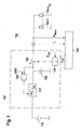
- Figure 1 shows the structure of a device 100 according to the invention for operating an internal combustion engine (not shown) with n cylinders zylindern .
- the device 100 is powered by a voltage source 110, usually the on-board battery of a motor vehicle.
- the device 100 comprises a control unit 120 for the individual activation of, in particular, piezo actuators 130-1... 130-n cylinders for injecting fuel into the cylinders assigned to the actuators.
- piezo actuators 130-1... 130-n cylinders for injecting fuel into the cylinders assigned to the actuators.
- each cylinder has an associated actuator, so that the number of actuators n cyl is equal to the number of cylinders n cyl .
- the control unit 120 includes in its interior a DC / DC converter 122 for stepping up the battery voltage to a required value of preferably 240 V.
- This output voltage of the DC / DC converter 122 is buffered in a buffer capacitor 124 and used to drive the actuators 130-1 ... 130-n cyl provided.
- This power supply within the controller 120 is designed to provide, if possible, any electrical power required by the actuators therefor. If required, this power supply also provides, at least in the short term, electrical power of a magnitude above its own nominal power output.
- FIG. 2 shows the basic functional principle of the regulating device 140 according to the invention.
- Method step S3 a reduction of the actuators future total consumed electrical power by the control device 140 in cooperation with the control unit 120 causes.
- the voltage swing ⁇ U represents the difference between the switch-off voltage U Ab and 0 V and, in the case of a discharge process E, the difference between the stationary final voltage U Lstat and 0 V, as illustrated in FIG.
- the correction factor f_Corr_z it is possible to calculate the charging or discharging energy W Li , W Ei from the voltage swing ⁇ U and the discharged charge Q of a charging or discharging cycle, as in the energy measuring device 142.
- the correction factors f_Corr_z z are not constants, but parameters which depend on the values determining the respective curve shape. These values are typically the voltage swing ⁇ U_z, the mechanical counterforce F_A at the piezo actuator and the actuator stroke ⁇ 1.
- FIG. 4 graphically illustrates the profile of the measuring voltage U Mess for realizing a single injection within an injection cycle. It can be seen that the charging process L begins after a certain delay time .DELTA.t and then characterized by a substantially linear increase of the measured voltage U measurement and thus the voltage supplied to the actuator. As soon as the voltage across the actuator has reached a switch-off voltage threshold U Ab predetermined by the control unit 120, the charging process has ended and the voltage supply by the control unit is switched off via the switching device 126. Regardless, however, the voltage across the actuator still performs a brief overshoot, until it finally settles down to the size of a stationary charge end voltage U Lstat .
- Both the detected measuring voltage U Mess and the measured current I i , as well as the energy W Li , W Ei , which is calculated and output by the energy measuring device 142, are preferably subjected to a plausibility test. For this purpose, they are each compared with individually suitable threshold values, and in the event of overshooting or undershooting of these measured values, an error status message is issued.
- an energy diagnosis device 149 is provided in the control device 140 for the signals which represent the energy received and delivered by an actuator.
- Similar error messages are generated by the energy diagnosis device 149 when the electrical energy released by an actuator during a discharge process E or the energy consumption ⁇ W i determined from the difference between absorbed and emitted energy exceed or undercut predetermined minimum and maximum threshold values for injection.
- the multiplication device 147 and the divider 148 are provided in FIG. The calculated by means of these devices in the manner described above power consumption or power consumption P of n cyl actuators for n j injections is supplied to the controller 120 as a control or controlled variable.
- a power limiting device 129 is provided, which compares this control variable with a predetermined desired size.
- P It should be either the nominal output power of the controller or in particular the DC / DC converter means 122 or a measured at the beginning, that is at the start of the internal combustion engine torque converter. The latter represents a correlative substitute value for the nominal output power of the transducer. While the nominal output power of the transducer represents an absolute value, the measured transducer power is a relative magnitude that must be maintained by the power limiter 129 within a percent environment.
- the power limiting device 129 When the power limiting device 129 detects that the power requirement of the actuators is greater than that predetermined setpoint, it generates an internal control unit Control signal, which is a reduction of Power requirement of the actuators causes. This can basically done in different ways.
- the According to the invention preferred approach to reducing The power requirement of the actuators is that in the Within the scope of an injection cycle individual secondary injections be omitted. This procedure offers the Advantage that the associated limitations for the Driver of a motor vehicle with the corresponding built-in internal combustion engine are minimal. The vehicle would still be ready to drive; a possible impact would be for example, a higher combustion noise. These Approach is preferred because they are in the Comparison to other options shown below to reduce the power requirement for the driver the least restrictions.
- FIG. 5 shows a second exemplary embodiment of the control device 140 according to the invention. It differs from the first exemplary embodiment only in that it has a second alternative option for calculating the average electrical power consumed by preferably all the actuators 130-1 P illustrated.
- the second embodiment differs from the first embodiment in the calculation of the sought average power consumption P or more precisely in the calculation of the average power consumed P all actuators currently determined energy consumption ⁇ W Act per actor.
- this currently determined power consumption ⁇ W akt calculated in such a way that initially during a predetermined time interval after the start of the internal combustion engine, the measured energy consumption ⁇ W i in a normalization device 143 'is preferably normalized to a nominal energy consumption ⁇ W nom .
- the result of this normalization is referred to below as the deviation factor f i .
- the nominal energy consumption ⁇ W nom is calculated in a modified energy measuring device 142 'from the current actuator temperature T and the current switch-off voltage U Ab of the actuator or alternatively to the switch-off voltage from the rail pressure p Rail .
- the calculation of the nominal energy consumption ⁇ W nom per actuator from the mentioned variables is done with the aid of stored characteristic curves. Because both the cut-off voltage U Ab and the rail pressure P rail and the temperature of the actuator depend on the respective operating point of the internal combustion engine, the nominal energy consumption ⁇ W nom per actuator is also dependent on the current operating point of the internal combustion engine.
- the deviation factor f i calculated above in contrast to the average energy consumption and the nominal energy consumption ⁇ W nom, is independent of the operating point of the internal combustion engine and should ideally be one. This independence of the deviation factor f i from the current operating point of the internal combustion engine results from the fact that both the numerator and the denominator for calculating the deviation factor f i in the normalization device 143 'are each dependent on the current operating point of the internal combustion engine; due to the formation of quotients, this dependence then shortens for the resulting deviation factor. Because of this lack of dependence on the operating point of the deviation factor f i is a much more meaningful and much easier to handle measure for a possible change in the energy consumption of an actuator as the pure measured energy consumption ⁇ W i . Deviations from the nominal energy consumption can thus be determined before the measured energy consumption exceeds absolute limits.
- the deviation factor f i is preferably monitored in the power diagnosis device 149 as to whether he f a predetermined lower threshold value for him and i, falls below a predetermined or min for him upper threshold value and f i, max exceeds. In these cases, the energy diagnostic device 149 generates an error signal F.
- a regular recalculation or update of the deviation factor f i is preferably carried out only during the said predetermined time interval after the start of the internal combustion engine, because only during this time interval a required for a meaningful calculation of the average energy consumption ⁇ W i meaurement is possible. After this time interval, the deviation factor f i is frozen to a then current value.
- the factor f i is frozen or not, it is averaged in a modified averaging device 144 'over the number of cylinders n cyl or the number of actuators of the internal combustion engine.
- a modified time filter 145 'of the control device 140 is the average over the number of cylinders n cylinder or actuators deviation factor f additionally subjected to temporal filtering, in particular averaging, resulting in a time-averaged deviation factor f t results.
- this time-averaged deviation factor becomes f t used to obtain a currently determined average energy consumption ⁇ W act per actor to determine. This is done in such a way that the time-averaged deviation factor f t is multiplied by the mean nominal energy consumption ⁇ W nom per actuator calculated in the modified energy meter 142 '.
- the just described method for operating the Internal combustion engine are preferably each in shape realized a computer program, which then on the Device 100 and in particular on the control unit 120 expires.
- the computer program may be together if necessary with further computer programs for the control unit be stored in a computer-readable medium.
- the disk can be a floppy disk, a Compact Disc, a so-called flash memory or the like act.
- the software stored on the disk can then sold as a product to a customer.
- the computer program may be again together with other computer programs - without the use of a data carrier - via a electronic communication network, in particular the Internet, transmitted as a product to a customer and sold.
- a data carrier - via a electronic communication network, in particular the Internet, transmitted as a product to a customer and sold.
Landscapes
- Engineering & Computer Science (AREA)
- Chemical & Material Sciences (AREA)
- Combustion & Propulsion (AREA)
- Mechanical Engineering (AREA)
- General Engineering & Computer Science (AREA)
- Combined Controls Of Internal Combustion Engines (AREA)
- Electrical Control Of Air Or Fuel Supplied To Internal-Combustion Engine (AREA)
- Control Of Vehicle Engines Or Engines For Specific Uses (AREA)
Applications Claiming Priority (4)
| Application Number | Priority Date | Filing Date | Title |
|---|---|---|---|
| DE10344005 | 2003-09-23 | ||
| DE10344005 | 2003-09-23 | ||
| DE102004012428 | 2004-03-13 | ||
| DE102004012428A DE102004012428A1 (de) | 2003-09-23 | 2004-03-13 | Verfahren, Computerprogramm und Vorrichtung zum Betreiben einer Brennkraftmaschine |
Publications (3)
| Publication Number | Publication Date |
|---|---|
| EP1519025A2 true EP1519025A2 (fr) | 2005-03-30 |
| EP1519025A3 EP1519025A3 (fr) | 2011-03-09 |
| EP1519025B1 EP1519025B1 (fr) | 2013-05-15 |
Family
ID=34195766
Family Applications (1)
| Application Number | Title | Priority Date | Filing Date |
|---|---|---|---|
| EP04018896.3A Expired - Lifetime EP1519025B1 (fr) | 2003-09-23 | 2004-08-10 | Méthode et appareil d'exploitation d'un moteur à combustion |
Country Status (3)
| Country | Link |
|---|---|
| EP (1) | EP1519025B1 (fr) |
| CN (1) | CN100430590C (fr) |
| DE (1) | DE102004012428A1 (fr) |
Cited By (1)
| Publication number | Priority date | Publication date | Assignee | Title |
|---|---|---|---|---|
| WO2011054686A1 (fr) * | 2009-11-09 | 2011-05-12 | Continental Automotive Gmbh | Appareil de commande pour un moteur à combustion interne |
Families Citing this family (5)
| Publication number | Priority date | Publication date | Assignee | Title |
|---|---|---|---|---|
| DE102007059115B4 (de) | 2007-12-07 | 2021-09-02 | Robert Bosch Gmbh | Verfahren zum Betreiben eines piezoelektrischen Aktors |
| DE102009026840A1 (de) * | 2009-06-09 | 2010-12-16 | Robert Bosch Gmbh | Verfahren zum Überwachen des Betriebs eines Injektors |
| DE102010042844B4 (de) | 2010-10-25 | 2022-02-03 | Robert Bosch Gmbh | Verfahren zur Überwachung eines Steuergeräts für eine Einspritzanlage in einem Kraftfahrzeug |
| CN104750011A (zh) * | 2015-04-01 | 2015-07-01 | 成都慧农信息技术有限公司 | 一种农业物联网执行器功率监测系统及方法 |
| DE102018200032A1 (de) * | 2017-12-22 | 2019-06-27 | Robert Bosch Gmbh | Verfahren zum Betreiben einer Anordnung von Recheneinheiten |
Family Cites Families (9)
| Publication number | Priority date | Publication date | Assignee | Title |
|---|---|---|---|---|
| EP0371469B1 (fr) * | 1988-11-30 | 1995-02-08 | Toyota Jidosha Kabushiki Kaisha | Appareil pour actionner un élément piézo-électrique servant à ouvrir ou fermer une partie d'une vanne |
| DE19734895C2 (de) * | 1997-08-12 | 2002-11-28 | Siemens Ag | Vorrichtung und Verfahren zum Ansteuern wenigstens eines kapazitiven Stellgliedes |
| DE19841460B4 (de) * | 1998-09-10 | 2007-01-25 | Siemens Ag | Verfahren und Vorrichtung zum Ansteuern eines kapazitiven Stellglieds |
| DE19860762A1 (de) * | 1998-12-30 | 2000-07-06 | Bosch Gmbh Robert | Verfahren zum Schutz von Endstufen vor Übertemperatur |
| DE19954689A1 (de) * | 1999-11-13 | 2001-05-23 | Porsche Ag | Mehrzylindrige Brennkraftmaschine |
| EP1139444B1 (fr) * | 2000-04-01 | 2010-03-24 | Robert Bosch GmbH | Système d'injection de carburant |
| US6363315B1 (en) * | 2000-07-13 | 2002-03-26 | Caterpillar Inc. | Apparatus and method for protecting engine electronic circuitry from thermal damage |
| DE10210163A1 (de) * | 2002-03-07 | 2003-09-18 | Bosch Gmbh Robert | Verfahren und Vorrichtung zur Steuerung einer Brennkraftmaschine |
| DE10240493A1 (de) * | 2002-09-03 | 2004-03-11 | Robert Bosch Gmbh | Verfahren zum Betrieb einer Brennkraftmaschine |
-
2004
- 2004-03-13 DE DE102004012428A patent/DE102004012428A1/de not_active Withdrawn
- 2004-08-10 EP EP04018896.3A patent/EP1519025B1/fr not_active Expired - Lifetime
- 2004-09-23 CN CNB2004100798501A patent/CN100430590C/zh not_active Expired - Fee Related
Non-Patent Citations (1)
| Title |
|---|
| None |
Cited By (2)
| Publication number | Priority date | Publication date | Assignee | Title |
|---|---|---|---|---|
| WO2011054686A1 (fr) * | 2009-11-09 | 2011-05-12 | Continental Automotive Gmbh | Appareil de commande pour un moteur à combustion interne |
| DE102009052487B4 (de) | 2009-11-09 | 2019-10-10 | Continental Automotive Gmbh | Verfahren zum Betreiben eines Steuergerätes für eine Brennkraftmaschine |
Also Published As
| Publication number | Publication date |
|---|---|
| CN1601071A (zh) | 2005-03-30 |
| CN100430590C (zh) | 2008-11-05 |
| EP1519025A3 (fr) | 2011-03-09 |
| EP1519025B1 (fr) | 2013-05-15 |
| DE102004012428A1 (de) | 2005-04-28 |
Similar Documents
| Publication | Publication Date | Title |
|---|---|---|
| DE102016203835B4 (de) | Fahrzeugmotorsteuervorrichtung | |
| DE102009003977B3 (de) | Steuern des Stromflusses durch einen Spulenantrieb eines Ventils unter Verwendung eines Stromintegrals | |
| EP1381764B1 (fr) | Procede et dispositif pour commander un piezo-actionneur | |
| DE102006000072A1 (de) | Aufladungsunterstützungssteuerungssystem | |
| EP2507103B1 (fr) | Procédé et dispositif de commande de fonctions hybrides dans un véhicule automobile | |
| EP2945258A1 (fr) | Procédé de gestion de l'alimentation de courant électrique dans un véhicule automobile | |
| WO2022189221A2 (fr) | Procédé pour surveiller un système de batterie | |
| DE102008042981A1 (de) | Verfahren und Steuervorrichtung zur Ansteuerung eines Kraftstoffinjektors | |
| EP3737847B1 (fr) | Procédé pour commander et réguler un moteur à combustion interne avec générateur et moteur asynchrone, et moteur à combustion interne | |
| DE112018004769T5 (de) | Verbrennungskraftmaschinensteuerungssystem | |
| EP1519025B1 (fr) | Méthode et appareil d'exploitation d'un moteur à combustion | |
| DE102016213522A1 (de) | Verfahren und Vorrichtung zur Ansteuerung eines Piezoaktors eines Einspritzventils eines Kraftfahrzeugs | |
| WO2017016746A1 (fr) | Procédé permettant de faire fonctionner un convertisseur continu-continu polyphasé | |
| DE102011086063A1 (de) | Verfahren zum Betreiben einer Brennkraftmaschine und Steuereinrichtung hierfür | |
| DE102005060859B4 (de) | Verfahren und Vorrichtung zur Ansteuerung eines Elektromotors | |
| DE102013220613A1 (de) | Verfahren zum Ansteuern eines Kraftstoffinjektors | |
| WO2009013141A2 (fr) | Procédé et dispositif pour réguler un générateur de véhicule | |
| DE102016206108B4 (de) | Verfahren zum Betreiben einer Hochstrom-Last in einem Bordnetz | |
| DE10245690A1 (de) | Verfahren zum Bestimmen der Effektivspannung einer Batterie | |
| DE102004016894A1 (de) | Kraftstoffeinspritzanlage für einen Verbrennungsmotor und Verfahren zum Betreiben einer solchen | |
| EP3688298B1 (fr) | Procédé permettant de faire fonctionner un moteur à combustion interne muni d'un système d'injection et système d'injection permettant la mise en oeuvre dudit procédé | |
| EP2235599B1 (fr) | Procédé permettant de faire fonctionner un appareil de commande pour actionneurs thermosensibles | |
| DE102020117481A1 (de) | Heizeinrichtung für ein Kraftfahrzeug | |
| EP4344921B1 (fr) | Procédé de commande d'une chaîne cinématique dans un véhicule hybride et véhicule hybride | |
| WO2008116744A1 (fr) | Procédé et dispositif permettant de faire fonctionner une unité d'entraînement |
Legal Events
| Date | Code | Title | Description |
|---|---|---|---|
| PUAI | Public reference made under article 153(3) epc to a published international application that has entered the european phase |
Free format text: ORIGINAL CODE: 0009012 |
|
| AK | Designated contracting states |
Kind code of ref document: A2 Designated state(s): AT BE BG CH CY CZ DE DK EE ES FI FR GB GR HU IE IT LI LU MC NL PL PT RO SE SI SK TR |
|
| AX | Request for extension of the european patent |
Extension state: AL HR LT LV MK |
|
| PUAL | Search report despatched |
Free format text: ORIGINAL CODE: 0009013 |
|
| AK | Designated contracting states |
Kind code of ref document: A3 Designated state(s): AT BE BG CH CY CZ DE DK EE ES FI FR GB GR HU IE IT LI LU MC NL PL PT RO SE SI SK TR |
|
| AX | Request for extension of the european patent |
Extension state: AL HR LT LV MK |
|
| RIC1 | Information provided on ipc code assigned before grant |
Ipc: H03K 17/14 20060101ALI20110202BHEP Ipc: H01L 41/04 20060101ALI20110202BHEP Ipc: F02D 41/20 20060101AFI20041217BHEP Ipc: H03K 17/08 20060101ALI20110202BHEP Ipc: F02D 41/22 20060101ALI20110202BHEP |
|
| 17P | Request for examination filed |
Effective date: 20110909 |
|
| AKX | Designation fees paid |
Designated state(s): DE FR GB IT |
|
| 17Q | First examination report despatched |
Effective date: 20120716 |
|
| GRAP | Despatch of communication of intention to grant a patent |
Free format text: ORIGINAL CODE: EPIDOSNIGR1 |
|
| GRAS | Grant fee paid |
Free format text: ORIGINAL CODE: EPIDOSNIGR3 |
|
| GRAA | (expected) grant |
Free format text: ORIGINAL CODE: 0009210 |
|
| AK | Designated contracting states |
Kind code of ref document: B1 Designated state(s): DE FR GB IT |
|
| REG | Reference to a national code |
Ref country code: GB Ref legal event code: FG4D Free format text: NOT ENGLISH |
|
| REG | Reference to a national code |
Ref country code: DE Ref legal event code: R096 Ref document number: 502004014163 Country of ref document: DE Effective date: 20130711 |
|
| PLBE | No opposition filed within time limit |
Free format text: ORIGINAL CODE: 0009261 |
|
| STAA | Information on the status of an ep patent application or granted ep patent |
Free format text: STATUS: NO OPPOSITION FILED WITHIN TIME LIMIT |
|
| 26N | No opposition filed |
Effective date: 20140218 |
|
| REG | Reference to a national code |
Ref country code: DE Ref legal event code: R097 Ref document number: 502004014163 Country of ref document: DE Effective date: 20140218 |
|
| PGFP | Annual fee paid to national office [announced via postgrant information from national office to epo] |
Ref country code: GB Payment date: 20140821 Year of fee payment: 11 Ref country code: FR Payment date: 20140819 Year of fee payment: 11 |
|
| PGFP | Annual fee paid to national office [announced via postgrant information from national office to epo] |
Ref country code: IT Payment date: 20140825 Year of fee payment: 11 |
|
| PGFP | Annual fee paid to national office [announced via postgrant information from national office to epo] |
Ref country code: DE Payment date: 20151022 Year of fee payment: 12 |
|
| GBPC | Gb: european patent ceased through non-payment of renewal fee |
Effective date: 20150810 |
|
| PG25 | Lapsed in a contracting state [announced via postgrant information from national office to epo] |
Ref country code: IT Free format text: LAPSE BECAUSE OF NON-PAYMENT OF DUE FEES Effective date: 20150810 |
|
| REG | Reference to a national code |
Ref country code: FR Ref legal event code: ST Effective date: 20160429 |
|
| PG25 | Lapsed in a contracting state [announced via postgrant information from national office to epo] |
Ref country code: GB Free format text: LAPSE BECAUSE OF NON-PAYMENT OF DUE FEES Effective date: 20150810 |
|
| PG25 | Lapsed in a contracting state [announced via postgrant information from national office to epo] |
Ref country code: FR Free format text: LAPSE BECAUSE OF NON-PAYMENT OF DUE FEES Effective date: 20150831 |
|
| REG | Reference to a national code |
Ref country code: DE Ref legal event code: R119 Ref document number: 502004014163 Country of ref document: DE |
|
| PG25 | Lapsed in a contracting state [announced via postgrant information from national office to epo] |
Ref country code: DE Free format text: LAPSE BECAUSE OF NON-PAYMENT OF DUE FEES Effective date: 20170301 |