EP1519048A2 - Side channel compressor - Google Patents
Side channel compressor Download PDFInfo
- Publication number
- EP1519048A2 EP1519048A2 EP04022009A EP04022009A EP1519048A2 EP 1519048 A2 EP1519048 A2 EP 1519048A2 EP 04022009 A EP04022009 A EP 04022009A EP 04022009 A EP04022009 A EP 04022009A EP 1519048 A2 EP1519048 A2 EP 1519048A2
- Authority
- EP
- European Patent Office
- Prior art keywords
- side channel
- housing
- compressor according
- ring
- channel compressor
- Prior art date
- Legal status (The legal status is an assumption and is not a legal conclusion. Google has not performed a legal analysis and makes no representation as to the accuracy of the status listed.)
- Withdrawn
Links
Images

Classifications
-
- F—MECHANICAL ENGINEERING; LIGHTING; HEATING; WEAPONS; BLASTING
- F04—POSITIVE - DISPLACEMENT MACHINES FOR LIQUIDS; PUMPS FOR LIQUIDS OR ELASTIC FLUIDS
- F04D—NON-POSITIVE-DISPLACEMENT PUMPS
- F04D29/00—Details, component parts, or accessories
- F04D29/40—Casings; Connections of working fluid
- F04D29/403—Casings; Connections of working fluid especially adapted for elastic fluid pumps
-
- F—MECHANICAL ENGINEERING; LIGHTING; HEATING; WEAPONS; BLASTING
- F04—POSITIVE - DISPLACEMENT MACHINES FOR LIQUIDS; PUMPS FOR LIQUIDS OR ELASTIC FLUIDS
- F04D—NON-POSITIVE-DISPLACEMENT PUMPS
- F04D23/00—Other rotary non-positive-displacement pumps
- F04D23/008—Regenerative pumps
-
- F—MECHANICAL ENGINEERING; LIGHTING; HEATING; WEAPONS; BLASTING
- F04—POSITIVE - DISPLACEMENT MACHINES FOR LIQUIDS; PUMPS FOR LIQUIDS OR ELASTIC FLUIDS
- F04D—NON-POSITIVE-DISPLACEMENT PUMPS
- F04D29/00—Details, component parts, or accessories
- F04D29/40—Casings; Connections of working fluid
- F04D29/42—Casings; Connections of working fluid for radial or helico-centrifugal pumps
- F04D29/4206—Casings; Connections of working fluid for radial or helico-centrifugal pumps especially adapted for elastic fluid pumps
- F04D29/4226—Fan casings
-
- F—MECHANICAL ENGINEERING; LIGHTING; HEATING; WEAPONS; BLASTING
- F04—POSITIVE - DISPLACEMENT MACHINES FOR LIQUIDS; PUMPS FOR LIQUIDS OR ELASTIC FLUIDS
- F04D—NON-POSITIVE-DISPLACEMENT PUMPS
- F04D29/00—Details, component parts, or accessories
- F04D29/60—Mounting; Assembling; Disassembling
- F04D29/62—Mounting; Assembling; Disassembling of radial or helico-centrifugal pumps
- F04D29/624—Mounting; Assembling; Disassembling of radial or helico-centrifugal pumps especially adapted for elastic fluid pumps
- F04D29/626—Mounting or removal of fans
Definitions
- the invention relates to a side channel compressor with an annular bivalve impeller housing having an in rotatably mounted impeller surrounds him and with a Air intake and an air outlet is provided.
- the impeller housing consists of two housing shells, which are formed differently and by which an integrally formed bearing mount for the Impeller rolling bearings and a likewise molded Flange for flanging the electric motor driving the impeller wearing.
- the other housing shell is as a lid formed, which arranged distributed by means of edges Screw bolt with the housing shell supporting the impeller is screwed.
- Both housing shells are in the area of their outer edge each provided with a plane surface, in the assembled state, the flat surfaces in one perpendicular to the axis of rotation of the impeller extending Separating surface lie together.
- the function-related required centering of the lid to the impeller Overlying housing shell is done by a precisely fitting Turn in the lid and in this housing shell. Of the Air intake and the air outlet are at the Impeller mounted housing shell formed.
- the object of the invention is therefore a side channel blower to create, by a cheaper Impeller housing with improved sealing properties distinguished.
- the impeller housing of the new side channel compressor consists of two identically designed housing shells, each one at its outer edge one in the radial direction continuous plane surface carries.
- the housing shells are with their plane surfaces in a right angle to the Rotary axis of the impeller extending separating surface to each other lying clamped together in the axial direction.
- in the Areas of the plane surfaces is a ring running around arranged, through which the two housing shells against each other are centered.
- the ring is usually made of metal, in particular Steel, but it can also be made of a dimensionally stable plastic be prepared. He has an advantage in essence rectangular or square cross-sectional shape on. If the ring is designed as a sealing ring, he can have a dimensionally stable ring core, the one out a sealing material, for example. Polytetrafluoillerhylen existing Wearing sealing layer.
- the ring is on arranged radially outer edge of the two planar surfaces, however It is also possible in principle, the ring on the radially inner Provide edge of the two plane surfaces.
- These can be the both housing shells in the areas of their plane surface respectively have an open-edged annular groove, wherein the two annular grooves the interconnected housing shells to a complement in the circumferential direction extending channel in the the ring is arranged. This is a simple way positive, precise centering of the two housing shells guaranteed against each other.
- basically the ring is not in a channel of the type mentioned must be arranged. They are also embodiments conceivable in which the ring under radial Bias on a cylindrical peripheral surface of the housing shells is placed, wherein the ring at the radially outer or radially inner edge of the planar surfaces may be arranged can.
- Each of the housing shells is with a suction and a Outlet formed.
- a Closure means for example, a lid closed.
- housing shells can be increased by the fact that the housing shells on wear outside their mating surfaces on which the double-shell impeller housing of several compressor stages are accurately clamped axially with each other. To this Way it is possible to build multi-stage side channel blowers, the louder half shells included.
- the neighboring ones Impeller housing of the compressor stages are against each other centered, with only a housing shell a Includes bearing for a shaft carrying the wheels.
- the on the other identically designed housing shells existing Stock records remain empty.
- each housing shell one on the opposite each other lying shell sides opening passageway be formed so that the through channels next to each other lying housing shells to a total Complete continuous axial channel.
- This axial channel can be in two- or multi-stage execution one Return of compressed air through the entire housing enable. The necessary deflection of the air takes place by associated deflection, for example.
- the axial channel can also serve for the passage of a cooling medium.
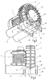
- the side channel compressor shown in Figs. 1 and 2 has a substantially annular impeller housing 1, which consists of two identical housing shells 2 and encloses a shown in Fig. 4 at 3 impeller.
- the impeller 3 is driven by an electric motor 4, the side and coaxial with the impeller housing. 1 is flanged.
- the two impeller housing 1 forming Housing shells 2 are identical.
- Each of the housing shells 2 has a side channel receiving the impeller 3 5 on, covering most of the circumference extends and a molded air inlet 6 with a molded air outlet 7 connects. Between the air inlet nozzle 6 and the air outlet 7 is a locking piece 8 is arranged, as in side channel compressors known per se.
- the air intake 6 and the air outlet 7 are in a common housing part 9 formed integrally on the housing shell. 2 is formed on both sides and a flat, perpendicular to the impeller axis 10 extending fitting surface 11, and 11a wearing.
- a through-channel 12 formed over the entire axial length of the Housing shell 2 extends and in the two opposite and mutually parallel mating surfaces 11, 11a empties.
- the passageway 12 is in the region of the locking piece 8 arranged and is not with the side channel 5 in Connection.
- the part-annular side channel 5 extends around a disc-shaped hub part 13 of the housing shell 2, on which a centric bearing housing 14 is formed, the for receiving a rolling bearing 16 for the impeller 3 bearing Shaft 10 is determined (see Fig. 4).
- the rolling bearing 16 is by a screwed bearing cap 17 to the outside too closed.
- the bearing housing 14 of a tubular, substantially cylindrical Ring flange 19 surrounded, on its outer end face a flat mating surface 20 carries, parallel to the Matching surface 11 is aligned with the housing part 9 and with this lies in a common plane.
- the electric motor 4 flanged while on the Electric motor 4 opposite impeller housing outside on the annular flange 19 of the corresponding housing shell. 2 a lid 21, screwed sealed against the mating surface 20 is.
- a support block 22 which is located between two cooling fins 23, the the Side channel 5 containing housing shell part outside in the For example, from Fig. 1, 4 apparent manner surrounded.
- the support block 22 protrudes slightly axially beyond the cooling fins 23 and carries on its outside a flat mating surface 24, with the mating surface 11 of the housing part 9 and the mating surface 20 of the annular flange 19 in a common plane lies.
- Flange 18 carries on its side facing away from the annular flange 19 Side a flat plane 25, which is perpendicular to the Impeller axis 100 runs and in a plane with the associated Mating surface 11 of the housing part 9 is located.
- an open-edge Ring groove 26 is formed, which has an L-shaped cross section and is bounded by two surfaces, from one at right angles and the other parallel to the Impeller axis 100 runs.
- the two housing shells 2 of an impeller housing 1 with their mating surfaces 25 to each other, so that the two Ring grooves 26 extending to a circumferentially Add channel 27, which has a rectangular cross-sectional shape having.
- the channel 27 is a closed dimensionally stable Ring 28 fitted tight tolerances, the two housing shells 2 centered against each other.
- the ring 28 is made of aluminum or, for example, from Steel, brass or even plastic and is with a Sealing material, in particular of polytetrafluoroethylene coated, so that it acts as a sealing ring.
- a Sealing material in particular of polytetrafluoroethylene coated, so that it acts as a sealing ring.
- the Ring 28 In the area of Air intake 6 and the air outlet 7 is the Ring 28, as at 29 in Fig. 5 for the air intake 6th represented, with a respective nozzle bore enclosing formed eye-like part.
- the two housing shells 2 are by rings around the Perimeter evenly distributed bolts axially braced together, not shown in detail are and pass through associated axial bores 30, which penetrate the flange 18 and the housing part 9.
- the Arrangement made such that the ring 28 with holes 30 is provided.
- housing shells 2 of the impeller shell 1 are, as already mentioned, the housing shells with their mating surfaces 25 against each other pressed and radially centered over the ring 28, wherein the ring 28 at the same time sealing the Impeller housing 1 in the areas perpendicular to the wheel axis 10 extending separating surface between the causes two housing shells. This seal is very effective because of the axially inserted into the holes 30 Screw bolt generated contact force immediately is transmitted to the ring 28.
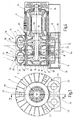
- FIG. 4 While in Figures 1 and 2, a single-stage side channel compressor is shown, the only one of two identical housing shells 2 composite impeller housing 1, Figures 4, 5 show a two-stage Embodiment in which two identical impeller housings 1, 1a, each of which encloses its own impeller 3, axially connected to each other.
- the adjacent housing shells are the second the impeller housing 1, 1a with their in a common Level lying mating surfaces 11, 20 and 24 to each other adjacent tensioned by tie rods 31 axially against each other.
- these two housing shells 2 by one to the impeller axis 10 coaxial inner steel existing centering ring 32 radially centered.
- the centering ring 32 engages positively in cross-section L-shaped, open-edged turns on the inside of the ring flange 19 one. It is inserted under preload clearance and, together with the mating surfaces 11, 20, 24 a exactly centered and with respect to the impeller shaft 10 exactly oriented at right angles to the two impeller housings 1, 1a.
- the impeller shaft 10 is through the two adjacent impeller housing 1, 1a continuously formed and carries both wheels 3, while the electric motor 4 to the outer housing shell 2 of the impeller housing 1a is flanged and the outer ring flange 19 of the other drive housing 1 through the lid 21 is closed.
- Fig. 4 also shows that the impeller shaft 10 on the impeller side only in a single roller bearing 16th is mounted, which on the electric motor 4 facing Side in the corresponding housing shell 2 of the impeller housing 1 is arranged.
- a second depository of the Impeller shaft 10 is in the bearing plate 34 of the electric motor 4 present and formed by a rolling bearing 35.
- the cover 37 is formed with two cover parts 38, the unused air intake 6 and the also not used air outlet 7 at this Close housing shell 2 sealed. At the same time on the lid part 37 two feet 39 for the side channel compressor molded, the a flat base 40 and Have holes 41 for anchoring screws.
- a separate Foot part 44 (Fig. 1, 2) provided on a tubular projection 45 of the respective muffler 42nd placed and braced against the housing part 9.
- the Foot part 44 also has a footprint 40 and vertical holes 41 for anchoring screws.
- the tubular Approaches 45 are, for example, provided with an external thread and in an internal thread of the respective nozzle 6,7 screwed.
- each axially outer housing shells 2 structurally identical air intake pipe 6 and air outlet 7 can carry the muffler 42 with the foot part 44 and the lid 37 against each other be swapped, i. that the muffler 42, related to the figures 1, 2 on the right side of the impeller housing 1 come to rest, if this is the special installation conditions of the side channel compressor appear appropriate to let.
- the silencer 42 and / or additionally other air guide elements eg connection pipes or hoses, valves, Pipe bends and the like occur, as is known is.
- the two in each case an impeller housing 1 or 1a forming housing shells 2 by the radially outer ring 28 against each other centered
- the arrangement could also be made that way be that the ring 28 on the inside of the Housing shells 2, i. arranged in the region of the side channels 5 is, so that is a similar arrangement as in the centering ring 32 between the two impeller housing 1, 1a.
- the centering ring 32 could be located radially outward, i. corresponding the ring 28.
- the impeller shaft 10 is in the illustrated two-stage Embodiment of FIG. 4 in one piece over the length the two compressor stages shown throughout and as explained, only in a single roller bearing 16th stored.
- each of the two compressor stages its own impeller shaft is assigned and the waves each by a front-side driver in the form of a positive shaft coupling Coaxially connected to each other.
- the impeller shaft contained in the impeller shell 1 stored in two bearings 16, which in the two Bearing housing 14 of this impeller housing 1 are used.
- a single bearing in particular by a in the electric motor 4 adjacent bearing housing 14 inserted bearings 16th is formed.
- the shaft coupling in the area of the interface between the two impeller housings 1, 1a is expediently designed so that they are about existing unavoidable Misalignment between the waves in the two impeller housings 1, 1a compensates.
Landscapes
- Engineering & Computer Science (AREA)
- Mechanical Engineering (AREA)
- General Engineering & Computer Science (AREA)
- Structures Of Non-Positive Displacement Pumps (AREA)
Abstract
Ein Seitenkanalverdichter weist wenigstens ein ringförmiges,
zweischaliges Laufradgehäuse (1) auf, das ein in
ihm drehbar gelagertes Laufrad (3) umschließt und mit einem
Luftansaug- und einem Luftauslassstutzen (6,7) versehen
ist. Das Laufradgehäuse besteht aus zwei gleich gestaltet
ausgebildeten Gehäuseschalen (2), die mit Planflächen an
einer rechtwinklig zu der Drehachse des Laufrades sich erstreckenden
Trennfläche aneinanderliegend in Achsrichtung
miteinander verspannt sind. Im Bereiche der Planflächen ist
ein ringsum laufender Ring (28) angeordnet, durch den die
beiden Gehäuseschalen (2) gegeneinander zentriert sind.

Description
Die Erfindung betrifft einen Seitenkanalverdichter mit einem ringförmigen zweischaligen Laufradgehäuse, das ein in ihm drehbar gelagertes Laufrad umschließt und mit einem Luftansaug- und einem Luftauslassstutzen versehen ist.The invention relates to a side channel compressor with an annular bivalve impeller housing having an in rotatably mounted impeller surrounds him and with a Air intake and an air outlet is provided.
Ein typisches Beispiel für solche Seitenkanalverdichter
ist in der DE 2 223 762 A1 beschrieben. Bei diesem Seitenkanalverdichter
besteht das Laufradgehäuse aus zwei Gehäuseschalen,
die unterschiedlich ausgebildet sind und von
denen eine eine angeformte Wälzlageraufnahme für das das
Laufrad lagernde Wälzlager und einen ebenfalls angeformten
Flansch zum Anflanschen des das Laufrad antreibenden Elektromotors
trägt. Die andere Gehäuseschale ist als Deckel
ausgebildet, der mittels randseitig verteilt angeordneter
Schraubenbolzen mit der das Laufrad lagernden Gehäuseschale
verschraubt ist. Beide Gehäuseschalen sind im Bereiche ihres
äußeren Randes jeweils mit einer Planfläche versehen,
wobei im zusammengebauten Zustand die Planflächen in einer
rechtwinklig zu der Drehachse des Laufrads sich erstreckenden
Trennfläche aneinander liegen. Die funktionsbedingt
erforderliche Zentrierung des Deckels zu der das Laufrad
lagernden Gehäuseschale geschieht durch eine passgenaue
Eindrehung in dem Deckel und in dieser Gehäuseschale. Der
Luftansaug- und der Luftauslassstutzen sind an der das
Laufrad lagernden Gehäuseschale angeformt.A typical example of such side channel blowers
is described in
Die Herstellung zweier unterschiedlicher Gehäuseschalen, von denen eine mit ihrer Lagerstelle für das Laufrad das eigentliche Gehäuse bildet, während die andere als Deckel ausgebildet ist, ist aufwendig. Außerdem ist die Abdichtung der beiden Gehäuseschalen gegeneinander im Bereiche der Trennfläche kritisch, u.a., weil fertigungsbedingt an dem Einpassbund ein Ringspalt vorhanden ist.The production of two different housing shells, one of which with its bearing for the impeller the actual housing forms, while the other as a lid is formed, is expensive. In addition, the seal the two housing shells against each other in the areas the interface critical, inter alia, because of production on the Einpassbund an annular gap is present.
Aufgabe der Erfindung ist es deshalb einen Seitenkanalverdichter zu schaffen, der sich durch ein preisgünstigeres Laufradgehäuse mit verbesserten Abdichtungseigenschaften auszeichnet.The object of the invention is therefore a side channel blower to create, by a cheaper Impeller housing with improved sealing properties distinguished.
Zur Lösung dieser Aufgabe weist der erfindungsgemäße
Seitenkanalverdichter die Merkmale des Patentanspruchs 1
auf.To solve this problem, the inventive
Side channel compressor, the features of
Das Laufradgehäuse des neuen Seitenkanalverdichters beseht aus zwei gleich gestaltet ausgebildeten Gehäuseschalen, von denen jede an ihrem äußeren Rand eine in Radialrichtung durchgehende Planfläche trägt. Die Gehäuseschalen sind mit ihren Planflächen in einer rechtwinklig zu der Drehachse des Laufrades sich erstreckenden Trennfläche aneinander liegend in Achsrichtung miteinander verspannt. Im Bereiche der Planflächen ist ein ringsum laufender Ring angeordnet, durch den die beiden Gehäuseschalen gegeneinander zentriert sind.The impeller housing of the new side channel compressor consists of two identically designed housing shells, each one at its outer edge one in the radial direction continuous plane surface carries. The housing shells are with their plane surfaces in a right angle to the Rotary axis of the impeller extending separating surface to each other lying clamped together in the axial direction. in the Areas of the plane surfaces is a ring running around arranged, through which the two housing shells against each other are centered.
Damit wird der Vorteil des Wegfalls der bisher üblichen beidseitigen Eindrehung in Gehäuse- und Deckelhalbschale erreicht, so dass jede Halbschale als "Gehäuse" und "Deckel" verwendbar ist. Da der fertigungsbedingte Ringspalt am Einpassbund entfällt, lässt sich eine bessere Abdichtung der Halbschalen gegeneinander erreichen. Dazu ist es zweckmäßig, dass der Ring als Dichtring ausgebildet ist, durch den ein im Bereiche der Trennflächen vorhandener Spalt abgedichtet ist. Die so erzielte Abdichtung ist in der Regel ausreichend, doch kann erforderlichenfalls im Bereich der beiden Planflächen zusätzlich zu dem Ring ein weiteres Dichtmittel zur Spaltabdichtung zwischen den beiden Planflächen vorgesehen sein.Thus, the advantage of eliminating the usual double-sided recess in housing and cover half shell achieved, so that each half shell called "housing" and "Lid" is usable. Since the production-related annular gap eliminates the Einpassbund, can be a better seal reach the half shells against each other. Is to it is expedient that the ring is designed as a sealing ring, by the one existing in the area of the separating surfaces Gap is sealed. The seal thus obtained is in usually sufficient, but may be necessary in the Area of the two flat surfaces in addition to the ring another sealant for gap sealing between the two Planar be provided.
Der Ring besteht in der Regel aus Metall, insbesondere Stahl, er kann aber auch aus einem formbeständigen Kunststoff hergestellt sein. Er weist mit Vorteil eine im Wesentlichen rechteckige oder quadratische Querschnittsgestalt auf. Wenn der Ring als Dichtring ausgebildet ist, kann er einen formstabilen Ringkern aufweisen, der eine aus einem Dichtmaterial bspw. aus Polytetrafluoräthylen bestehende Abdichtschicht trägt.The ring is usually made of metal, in particular Steel, but it can also be made of a dimensionally stable plastic be prepared. He has an advantage in essence rectangular or square cross-sectional shape on. If the ring is designed as a sealing ring, he can have a dimensionally stable ring core, the one out a sealing material, for example. Polytetrafluoräthylen existing Wearing sealing layer.
In einer zweckmäßigen Ausführungsform ist der Ring am radial äußeren Rand der beiden Planflächen angeordnet, doch ist es grundsätzlich auch möglich, den Ring am radial inneren Rand der beiden Planflächen vorzusehen. Dazu können die beiden Gehäuseschalen im Bereiche ihrer Planfläche jeweils eine randoffene Ringnut aufweisen, wobei die beiden Ringnuten der miteinander verbundenen Gehäuseschalen sich zu einem in Umfangsrichtung erstreckenden Kanal ergänzen, in dem der Ring angeordnet ist. Damit ist auf einfache Weise eine formschlüssige, passgenaue Zentrierung der beiden Gehäuseschalen gegeneinander gewährleistet. Zu bemerken ist allerdings, dass grundsätzlich der Ring nicht in einem Kanal der erwähnten Art angeordnet sein muss. Es sind auch Ausführungsformen denkbar, bei denen der Ring unter radialer Vorspannung auf eine zylindrische Umfangsfläche der Gehäuseschalen aufgesetzt ist, wobei der Ring am radial äußeren oder radial inneren Rand der Planflächen angeordnet sein kann.In an expedient embodiment, the ring is on arranged radially outer edge of the two planar surfaces, however It is also possible in principle, the ring on the radially inner Provide edge of the two plane surfaces. These can be the both housing shells in the areas of their plane surface respectively have an open-edged annular groove, wherein the two annular grooves the interconnected housing shells to a complement in the circumferential direction extending channel in the the ring is arranged. This is a simple way positive, precise centering of the two housing shells guaranteed against each other. It should be noted, however, that basically the ring is not in a channel of the type mentioned must be arranged. They are also embodiments conceivable in which the ring under radial Bias on a cylindrical peripheral surface of the housing shells is placed, wherein the ring at the radially outer or radially inner edge of the planar surfaces may be arranged can.
Jede der Gehäuseschalen ist mit einem Ansaug- und einem Auslassstutzen ausgebildet. Im zusammengesetzten Zustand sind die jeweils nicht benutzten Stutzen durch ein Verschlussmittel, bspw. einen Deckel verschlossen.Each of the housing shells is with a suction and a Outlet formed. In the assembled state are the unused each neck through a Closure means, for example, a lid closed.
Die vielseitige Einsatzmöglichkeit der Gehäuseschalen kann dadurch erhöht werden, dass die Gehäuseschalen auf ihrer Außenseite jeweils Passflächen tragen, an denen die zweischaligen Laufradgehäuse mehrerer Verdichterstufen passgenau axial miteinander verspannbar sind. Auf diese Weise ist es möglich mehrstufige Seitenkanalverdichter aufzubauen, die lauter gleiche Halbschalen enthalten. Die benachbarten Laufradgehäuse der Verdichterstufen sind gegeneinander zentriert, wobei lediglich eine Gehäuseschale ein Lager für eine die Laufräder tragende Welle enthält. Die an den anderen gleich gestalteten Gehäuseschalen vorhandenen Lageraufnahmen bleiben leer.The versatile use of housing shells can be increased by the fact that the housing shells on wear outside their mating surfaces on which the double-shell impeller housing of several compressor stages are accurately clamped axially with each other. To this Way it is possible to build multi-stage side channel blowers, the louder half shells included. The neighboring ones Impeller housing of the compressor stages are against each other centered, with only a housing shell a Includes bearing for a shaft carrying the wheels. The on the other identically designed housing shells existing Stock records remain empty.
In jeder Gehäuseschale kann ein auf den einander gegenüber liegenden Schalenseiten mündender Durchgangskanal ausgebildet sein, so dass die Durchgangskanäle nebeneinander liegender Gehäuseschalen sich zu einem insgesamt durchgehenden Axialkanal ergänzen. Durch diesen Axialkanal lässt sich bei zwei- oder mehrstufiger Ausführung eine Rückführung der komprimierten Luft durch das Gesamtgehäuse ermöglichen. Die notwendige Umlenkung der Luft erfolgt durch zugeordnete Umlenkmittel, bspw. in Form von aufgesetzten oder eingefügten Umlenkstücken. Der Axialkanal kann auch zur Durchleitung eines Kühlmediums dienen.In each housing shell, one on the opposite each other lying shell sides opening passageway be formed so that the through channels next to each other lying housing shells to a total Complete continuous axial channel. Through this axial channel can be in two- or multi-stage execution one Return of compressed air through the entire housing enable. The necessary deflection of the air takes place by associated deflection, for example. In the form of patch or inserted deflectors. The axial channel can also serve for the passage of a cooling medium.
Weitere Ausgestaltungen des erfindungsgemäßen Seitenkanalverdichters sind Gegenstand von Unteransprüchen.Further embodiments of the side channel compressor according to the invention are the subject of dependent claims.
In der Zeichnung ist ein Ausführungsbeispiel des Gegenstandes der Erfindung dargestellt. Es zeigen:
- Fig. 1
- einen Seitenkanalverdichter, gemäß der Erfindung, in perspektivischer Darstellung,
- Fig. 2
- den Seitenkanalverdichter nach Fig. 1 in einer Seitenansicht,
- Fig. 3
- den Seitenkanalverdichter nach Fig. 1 in einer Seitenansicht auf die Motorseite und
- Fig. 4
- den Seitenkanalverdichter nach Fig. 1 in zweistufiger Ausführung, in einer Schnittdarstellung entsprechend der Linie IV-IV der Fig. 3 und
- Fig. 5
- den Seitenkanalverdichter nach Fig. 4 in einer perspektivischen Explosionsdarstellung.
- Fig. 1
- a side channel compressor, according to the invention, in perspective view,
- Fig. 2
- the side channel compressor of FIG. 1 in a side view,
- Fig. 3
- the side channel compressor of FIG. 1 in a side view of the engine side and
- Fig. 4
- 1 in two-stage design, in a sectional view corresponding to the line IV-IV of Fig. 3 and the side channel compressor of FIG
- Fig. 5
- the side channel compressor of Fig. 4 in a perspective exploded view.
Der in den Fig. 1 und 2 dargestellte Seitenkanalverdichter
weist ein im Wesentlichen ringförmiges Laufradgehäuse
1 auf, das aus zwei identischen Gehäuseschalen 2 besteht
und ein in Fig. 4 bei 3 dargestelltes Laufrad umschließt.
Das Laufrad 3 ist von einem Elektromotor 4 angetrieben,
der seitlich und koaxial an das Laufradgehäuse 1
angeflanscht ist. Die das Laufradgehäuse 1 bildenden beiden
Gehäuseschalen 2 sind identisch ausgebildet. Jede der Gehäuseschalen
2 weist einen das Laufrad 3 aufnehmenden Seitenkanal
5 auf, der sich über den größten Teil des Umfangs
erstreckt und einen angeformten Lufteinlassstutzen 6 mit
einem angeformten Luftauslassstutzen 7 verbindet. Zwischen
dem Lufteinlassstutzen 6 und dem Luftauslassstutzen 7 ist
ein Sperrstück 8 angeordnet, wie dies bei Seitenkanalverdichtern
an sich bekannt ist. Der Luftansaugstutzen 6 und
der Luftauslassstutzen 7 sind in einem gemeinsamen Gehäuseteil
9 ausgebildet, das einstückig an der Gehäuseschale 2
angeformt ist und beidseitig eine ebene, rechtwinklig zu
der Laufradachse 10 verlaufende Passfläche 11, bzw. 11a
trägt. In dem Gehäuseteil 9 ist zwischen dem Luftansaugstutzen
6 und dem Luftauslassstutzen 7 ein Durchgangskanal
12 ausgebildet, der sich über die ganze axiale Länge der
Gehäuseschale 2 erstreckt und in den beiden einander gegenüberliegenden
und zueinander parallelen Passflächen 11, 11a
mündet. Der Durchgangskanal 12 ist im Bereiche des Sperrstücks
8 angeordnet und steht mit dem Seitenkanal 5 nicht in
Verbindung.The side channel compressor shown in Figs. 1 and 2
has a substantially
Der teilringförmige Seitenkanal 5 erstreckt sich rings
um ein scheibenförmiges Nabenteil 13 der Gehäuseschale 2,
an dem ein zentrisches Lagergehäuse 14 ausgebildet ist, das
zur Aufnahme eines Wälzlagers 16 für die das Laufrad 3 tragende
Welle 10 bestimmt ist (vgl. Fig. 4). Das Wälzlager 16
ist durch einen aufgeschraubten Lagerdeckel 17 nach außen
zu abgeschlossen. Im radialen Abstand ist das Lagergehäuse
14 von einem rohrförmigen, im Wesentlichen zylindrischen
Ringflansch 19 umgeben, der an seiner außenliegenden Stirnseite
eine ebene Passfläche 20 trägt, die parallel zu der
Passfläche 11 an dem Gehäuseteil 9 ausgerichtet ist und mit
dieser in einer gemeinsamen Ebene liegt. An dem zu der
Laufradachse 100 koaxialen Ringflansch 19 einer Gehäuseschale
2 des Laufradgehäuses 1 ist, wie aus Fig. 4 zu ersehen,
der Elektromotor 4 angeflanscht, während auf der dem
Elektromotor 4 gegenüber liegenden Laufradgehäuseaußenseite
auf den Ringflansch 19 der entsprechenden Gehäuseschale 2
ein Deckel 21, gegenüber der Passfläche 20 abgedichtet aufgeschraubt
ist.The part-annular side channel 5 extends around
a disc-shaped
Auf der dem Gehäuseteil 9 diametral gegenüberliegenden
Seite ist an der Gehäuseschale 2 ein Abstützblock 22 angeformt,
der zwischen zwei Kühlrippen 23 liegt, die den den
Seitenkanal 5 enthaltenden Gehäuseschalenteil außen in der
bspw. aus Fig. 1, 4 ersichtlichen Weise umgeben. Der Abstützblock
22 ragt axial etwas über die Kühlrippen 23 vor
und trägt auf seiner Außenseite eine ebene Passfläche 24,
die mit der Passfläche 11 des Gehäuseteils 9 und der Passfläche
20 des Ringflansches 19 in einer gemeinsamen Ebene
liegt.On the
Ein am äußeren Rand der Gehäuseschale 2 angeordneter
Flansch 18 trägt auf seiner dem Ringflansch 19 abgewandten
Seite eine ebene Planfläche 25, die rechtwinklig zu der
Laufradachse 100 verläuft und in einer Ebene mit der zugeordneten
Passfläche 11 des Gehäuseteils 9 liegt. Im Bereiche
der Passfläche 25 ist in dem Flansch 18 eine randoffene
Ringnut 26 ausgebildet, die einen L-förmigen Querschnitt
aufweist und von zwei Flächen begrenzt ist, von
denen eine rechtwinklig und die andere parallel zu der
Laufradachse 100 verläuft. Im zusammengebauten Zustand liegen
die beiden Gehäuseschalen 2 eines Laufradgehäuses 1 mit
ihren Passflächen 25 aneinander an, so dass die beiden
Ringnuten 26 sich zu einem in Umfangsrichtung erstreckenden
Kanal 27 ergänzen, der eine rechteckige Querschnittsgestalt
aufweist. In den Kanal 27 ist ein geschlossener formstabiler
Ring 28 eng toleriert eingepasst, der die beiden Gehäuseschalen
2 gegeneinander zentriert. A arranged on the outer edge of the
Der Ring 28 besteht aus Aluminium oder bspw. aus
Stahl, Messing oder auch aus Kunststoff und ist mit einem
Dichtmaterial, insbesondere aus Polytetrafluoräthylen beschichtet,
so dass er als Dichtring wirkt. Im Bereiche des
Luftansaugstutzens 6 und des Luftauslassstutzens 7 ist der
Ring 28, wie bei 29 in Fig. 5 für den Luftansaugstutzen 6
dargestellt, mit einem die jeweilige Stutzenbohrung umschließenden
ösenartigen Teil ausgebildet.The
Die beiden Gehäuseschalen 2 sind durch rings um den
Umfang gleichmäßig verteilt angeordnete Schraubenbolzen
axial miteinander verspannt, die im Einzelnen nicht dargestellt
sind und durch zugeordnete Axialbohrungen 30 verlaufen,
welche den Flansch 18 und das Gehäuseteil 9 durchdringen.
Bei dem dargestellten Ausführungsbeispiel ist die
Anordnung so getroffen, dass auch der Ring 28 mit Bohrungen
30 versehen ist. Bei axial miteinander verspannten Gehäuseschalen
2 des Laufradgehäuses 1 sind, wie bereit erwähnt,
die Gehäuseschalen mit ihren Passflächen 25 gegeneinander
gepresst und über den Ring 28 radial gegeneinander zentriert,
wobei der Ring 28 gleichzeitig die Abdichtung des
Laufradgehäuses 1 im Bereiche der rechtwinklig zu der Laufradachse
10 sich erstreckenden Trennfläche zwischen den
beiden Gehäuseschalen bewirkt. Diese Abdichtung ist sehr
wirksam, weil die von den axial in die Bohrungen 30 eingesetzten
Schraubenbolzen erzeugte Anpresskraft unmittelbar
auf den Ring 28 übertragen wird.The two
Während in den Figuren 1 und 2 ein einstufiger Seitenkanalverdichter
dargestellt ist, der lediglich ein aus zwei
identischen Gehäuseschalen 2 zusammengesetztes Laufradgehäuse
1 aufweist, zeigen die Figuren 4, 5 eine zweistufige
Ausführungsform, bei der zwei identische Laufradgehäuse 1,
1a, von denen jedes ein eigenes Laufrad 3 umschließt, axial
miteinander verbunden sind. Wie insbesondere aus Fig. 4 zu
entnehmen, sind die einander benachbarten Gehäuseschalen 2
der Laufradgehäuse 1, 1a mit ihren in einer gemeinsamen
Ebene liegenden Passflächen 11, 20 und 24 satt aneinander
anliegend durch Zuganker 31 axial gegeneinander verspannt.
Außerdem sind diese beiden Gehäuseschalen 2 durch einen zu
der Laufradachse 10 koaxialen innen liegenden aus Stahl
bestehenden Zentrierring 32 radial zentriert. Der Zentrierring
32 greift formschlüssig in im Querschnitt L-förmige,
randoffene Ausdrehungen auf der Innenseite des Ringflansches
19 ein. Er ist unter Vorspannung spielfrei eingesetzt
und ergibt zusammen mit den Passflächen 11, 20, 24 eine
exakt zentrierte und bezüglich der Laufradwelle 10 genau
rechtwinklig ausgerichtete Orientierung der beiden Laufradgehäuse
1, 1a. Die Laufradwelle 10 ist durch die beiden
nebeneinander liegenden Laufradgehäuse 1, 1a durchgehend
ausgebildet und trägt beide Laufräder 3, während der Elektromotor
4 an die außenliegende Gehäuseschale 2 des Laufradgehäuses
1a angeflanscht ist und der außenliegende Ringflansch
19 des anderen Laufwerkgehäuses 1 durch den Deckel
21 verschlossen ist.While in Figures 1 and 2, a single-stage side channel compressor
is shown, the only one of two
Fig. 4 zeigt außerdem, dass die Laufradwelle 10 auf
der Laufradseite lediglich in einem einzigen Wälzlager 16
gelagert ist, das auf der dem Elektromotor 4 zugewandten
Seite in der entsprechenden Gehäuseschale 2 des Laufradgehäuses
1 angeordnet ist. Eine zweite Lagerstelle der
Laufradwelle 10 ist in dem Lagerschild 34 des Elektromotors
4 vorhanden und durch ein Wälzlager 35 gebildet.Fig. 4 also shows that the
Ähnlich der anhand der Fig. 4, 5 beschriebenen zweistufigen
Ausbildung des Seitenkanalverdichters sind auch
Ausführungsformen möglich, bei denen in entsprechender Weise
mehrere Laufradgehäuse 1, 1a axial aneinander angeflanscht
sind, um Seitenkanalverdichter mit mehr als zwei
Verdichterstufen zu schaffen. Bei allen diesen mehrstufigen
Seitenkanalverdichtern sind die Durchgangskanäle 12 der
einzelnen Gehäuseschalen 2 miteinander fluchtend abgedichtet,
stumpf aneinander stoßend miteinander verbunden, so
dass sich ein über die ganze Axiallänge des Verdichters
durchgehender Axialkanal ergibt (vgl. Fig. 4). Endseitig
aufgesetzte Umlenkstücke 36 erlauben es, den Luftauslassstutzen
7 einer Verdichterstufe mit dem Lufteinlassstutzen
6 einer nachfolgenden Verdichterstufe zu verbinden, um eine
Verwendungsmöglichkeit des durchgehenden Axialkanals zu
erwähnen. Eine andere Verwendungsmöglichkeit besteht darin,
Kühlmittel durch den Kanal durchzuleiten, um anfallende
Verdichtungswärme abzuführen. Davon abgesehen, kann der in
diesem Fall nicht benutzte Durchgangskanal 12 durch einen
an der außenliegenden Gehäuseschale 2 des Laufradgehäuses 1
angebrachten Deckel 37 (Fig. 1,5) verschlossen werden.Similar to the described with reference to FIGS. 4, 5 two-stage
Training the side channel blower are also
Embodiments possible in which, in a corresponding manner
a plurality of
Der Deckel 37 ist mit zwei Deckelteilen 38 ausgebildet,
die den nicht benutzten Luftansaugstutzen 6 und den
ebenfalls nicht benutzten Luftauslassstutzen 7 an dieser
Gehäuseschale 2 abgedichtet verschließen. Gleichzeitig sind
an dem Deckelteil 37 zwei Standfüße 39 für den Seitenkanalverdichter
angeformt, die eine ebene Standfläche 40 und
Bohrungen 41 für Verankerungsschrauben aufweisen.The
An den Luftansaugstutzen 6 und den Luftauslassstutzen
7 der gegenüberliegenden, mit dem Elektromotor 4 verschraubten
Gehäuseschale 2 sind zwei Schalldämpfer 42 angeschlossen,
die an ihren freien Stirnseiten Anschlussflansche
43 für Luftzu- bzw. Abfuhrleitungen aufweisen (vgl.
Fig. 3). Zwischen dem jeweiligen Schalldämpfer 42 und dem
Gehäuseteil 9 der zugeordneten Gehäuseschale 2 ist ein separates
Fußteil 44 (Fig. 1, 2) vorgesehen, das auf einen
rohrförmigen Ansatz 45 des jeweiligen Schalldämpfers 42
aufgesetzt und gegen das Gehäuseteil 9 verspannt ist. Das
Fußteil 44 weist ebenfalls eine Aufstellfläche 40 und Vertikalbohrungen
41 für Verankerungsschrauben auf. Die rohrförmigen
Ansätze 45 sind bspw. mit einem Außengewinde versehen
und in ein Innengewinde des jeweiligen Stutzens 6,7
eingeschraubt.To the
Da alle Gehäuseschalen 2 identisch ausgebildet sind
und die bei ein- oder mehrstufiger Ausführung des Seitenkanalverdichters
jeweils axial außen liegenden Gehäuseschalen
2 konstruktiv gleich gestalteten Lufteinlassstutzen 6
und Luftauslassstutzen 7 tragen, können die Schalldämpfer
42 mit dem Fußteil 44 und der Deckel 37 auch gegeneinander
vertauscht werden, d.h. dass die Schalldämpfer 42, bezogen
auf die Figuren 1, 2 auf der rechten Seite des Laufradgehäuses
1 zu liegen kommen, wenn dies die besonderen Einbauverhältnisse
des Seitenkanalverdichters zweckmäßig erscheinen
lassen. Selbstverständlich können anstelle der Schalldämpfer
42 und/oder zusätzlich dazu auch andere Luftleitelemente,
bspw. Anschlussrohre oder -schläuche, Ventile,
Rohrbögen und dergleichen treten, wie dies an sich bekannt
ist.Since all
Während bei der dargestellten Ausführungsform die beiden
jeweils ein Laufradgehäuse 1 oder 1a bildenden Gehäuseschalen
2 durch den radial außen liegenden Ring 28 gegeneinander
zentriert sind, könnte die Anordnung auch so getroffen
werden, dass der Ring 28 auf der Innenseite der
Gehäuseschalen 2, d.h. im Bereiche der Seitenkanäle 5 angeordnet
ist, so dass sich eine ähnliche Anordnung wie bei
dem Zentrierring 32 zwischen den beiden Laufradgehäuse 1,
1a ergibt. Dazu ist zu bemerken, dass auch der Zentrierring
32 radial außen liegend angeordnet sein könnte, d.h. entsprechend
dem Ring 28.While in the illustrated embodiment, the two
in each case an
Die Laufradwelle 10 ist bei der dargestellten zweistufigen
Ausführungsform nach Fig. 4 einstückig über die Länge
der beiden Verdichterstufen durchgehend dargestellt und,
wie erläutert, lediglich in einem einzigen Wälzlager 16
gelagert. Es sind aber auch Ausführungsformen denkbar, bei
denen jeder der beiden Verdichterstufen eine eigene Laufradwelle
zugeordnet ist und die Wellen jeweils durch einen
stirnseitigen Mitnehmer in Form einer formschlüssigen Wellenkupplung
koaxial miteinander verbunden sind. In diesem
Falle ist die in dem Laufradgehäuse 1 enthaltene Laufradwelle
in zwei Wälzlagern 16 gelagert, die in die beiden
Lagergehäuse 14 dieses Laufradgehäuses 1 eingesetzt sind.
Bei dem dargestellen zweistufigen Ausführungsbeispiel genügt
für das andere Laufradgehäuse 1a eine einzige Lagerstelle,
die insbesondere durch ein in das dem Elektromotor
4 benachbarte Lagergehäuse 14 eingesetztes Wälzlager 16
gebildet ist. Die Wellenkupplung im Bereiche der Trennfläche
zwischen den beiden Laufradgehäusen 1, 1a ist zweckmäßigerweise
so ausgebildet, dass sie etwa vorhandene unvermeidbare
Fluchtungsfehler zwischen den Wellen in den
beiden Laufradgehäusen 1, 1a ausgleicht.The
Claims (18)
Applications Claiming Priority (2)
| Application Number | Priority Date | Filing Date | Title |
|---|---|---|---|
| DE10344718 | 2003-09-26 | ||
| DE2003144718 DE10344718B3 (en) | 2003-09-26 | 2003-09-26 | Side channel compressor has turbine wheel housing provided by 2 identical housing shells enclosed adjacent their planar separation surfaces by peripheral ring |
Publications (2)
| Publication Number | Publication Date |
|---|---|
| EP1519048A2 true EP1519048A2 (en) | 2005-03-30 |
| EP1519048A3 EP1519048A3 (en) | 2008-04-09 |
Family
ID=33495263
Family Applications (1)
| Application Number | Title | Priority Date | Filing Date |
|---|---|---|---|
| EP04022009A Withdrawn EP1519048A3 (en) | 2003-09-26 | 2004-09-16 | Side channel compressor |
Country Status (3)
| Country | Link |
|---|---|
| EP (1) | EP1519048A3 (en) |
| CN (1) | CN1601113A (en) |
| DE (1) | DE10344718B3 (en) |
Cited By (1)
| Publication number | Priority date | Publication date | Assignee | Title |
|---|---|---|---|---|
| CN113167284A (en) * | 2018-11-22 | 2021-07-23 | 罗伯特·博世有限公司 | Side channel compressor for conveying and/or compressing gaseous medium for fuel cell system |
Families Citing this family (9)
| Publication number | Priority date | Publication date | Assignee | Title |
|---|---|---|---|---|
| DE102005052077B4 (en) * | 2005-10-28 | 2016-11-24 | Man Diesel & Turbo Se | Device for the lateral mounting and dismounting of a compressor barrel |
| JP2010509527A (en) * | 2006-11-06 | 2010-03-25 | ボーグワーナー・インコーポレーテッド | Double inlet regenerative air pump |
| DE102007053016A1 (en) * | 2007-11-05 | 2009-05-07 | Gardner Denver Deutschland Gmbh | Side Channel Blowers |
| CN102454636A (en) * | 2010-10-20 | 2012-05-16 | 李正奇 | Discharge stage for high-temperature and high-pressure centrifugal pump |
| DE102011004512A1 (en) * | 2011-02-22 | 2012-08-23 | Gardner Denver Deutschland Gmbh | Side channel machine arrangement |
| CN104500419B (en) * | 2014-11-20 | 2016-08-17 | 宁波升鸿机械设备有限公司 | A kind of two section type high pressure blower |
| DE102015111469A1 (en) * | 2015-07-15 | 2017-01-19 | Gebr. Becker Gmbh | Side channel compressor and side channel machine |
| DE102017200846A1 (en) | 2017-01-19 | 2018-07-19 | Mahle International Gmbh | Conveyor for driving a gas |
| CN113027823A (en) * | 2021-03-10 | 2021-06-25 | 苏州格力士实业有限公司 | Easily-disassembled and split-assembled vortex type air pump |
Family Cites Families (7)
| Publication number | Priority date | Publication date | Assignee | Title |
|---|---|---|---|---|
| DE2223762A1 (en) * | 1972-05-16 | 1973-11-29 | Elektror Karl W Mueller | PRESSURE AND VOLUME REGULATORS FOR MOTOR-DRIVEN COMPRESSORS FOR GASES OR FLUID DEVICES |
| AT369515B (en) * | 1979-06-12 | 1983-01-10 | Garvenswerke Pumpen Motoren Un | PUMP AND METHOD FOR INSTALLING A SEAL IN A PUMP |
| DE3105395A1 (en) * | 1981-02-14 | 1982-11-04 | Leonhard Schleicher Südmo-Armaturenfabrik GmbH, 7081 Riesbürg | Metallically sealed pipe connection, especially for the food and pharmacology industries |
| DE4221691C2 (en) * | 1992-07-02 | 1994-09-15 | Siemens Ag | Side channel machine with at least one impeller rotatably arranged in the housing of the machine |
| DE9215231U1 (en) * | 1992-11-09 | 1994-03-10 | Siemens AG, 80333 München | Compressor unit |
| DE9304435U1 (en) * | 1993-03-24 | 1993-06-09 | Leybold AG, 6450 Hanau | High vacuum pump with inlet flange |
| DE59609719D1 (en) * | 1995-09-15 | 2002-10-31 | Siemens Ag | Side Channel Blowers |
-
2003
- 2003-09-26 DE DE2003144718 patent/DE10344718B3/en not_active Expired - Fee Related
-
2004
- 2004-09-16 EP EP04022009A patent/EP1519048A3/en not_active Withdrawn
- 2004-09-27 CN CN 200410011763 patent/CN1601113A/en active Pending
Cited By (1)
| Publication number | Priority date | Publication date | Assignee | Title |
|---|---|---|---|---|
| CN113167284A (en) * | 2018-11-22 | 2021-07-23 | 罗伯特·博世有限公司 | Side channel compressor for conveying and/or compressing gaseous medium for fuel cell system |
Also Published As
| Publication number | Publication date |
|---|---|
| DE10344718B3 (en) | 2005-01-05 |
| EP1519048A3 (en) | 2008-04-09 |
| CN1601113A (en) | 2005-03-30 |
Similar Documents
| Publication | Publication Date | Title |
|---|---|---|
| DE69628755T2 (en) | LIQUID PUMP | |
| EP1394365B1 (en) | Turbocharger shaft sealing | |
| DE69329396T2 (en) | Pump housing in sheet metal construction | |
| EP1891335B1 (en) | Radial fan | |
| DE69408246T2 (en) | Fuel pump | |
| DE69206051T2 (en) | Motor driven pump system. | |
| DE69613659T2 (en) | Vehicle pump housing | |
| DE60203214T2 (en) | Turbine blade with labyrinth cutting gasket | |
| DE102018125031A1 (en) | Pump, in particular for a liquid circuit in a vehicle | |
| EP2631488A2 (en) | Vacuum pump | |
| DE102021204716A1 (en) | Radial piston pump, in particular radial piston compressor | |
| DE60035842T2 (en) | vacuum pumps | |
| EP2610497A1 (en) | Pump power unit | |
| EP2818721A1 (en) | Centrifugal pump | |
| WO2020074318A1 (en) | Pump, in particular for a liquid circuit in a vehicle | |
| DE10344718B3 (en) | Side channel compressor has turbine wheel housing provided by 2 identical housing shells enclosed adjacent their planar separation surfaces by peripheral ring | |
| EP1519049A2 (en) | Side channel compressor with annular casing | |
| DE4326323A1 (en) | Axial piston compressor for air conditioning system - uses centering device to align drive shaft with cylinder block | |
| EP0797737B1 (en) | Centrifugal pump case with an inside case made of plastic | |
| DE102011053148A1 (en) | Radial piston pump used in vehicle, has check valves that are arranged in extension of pressure oil bores in housing cover provided with pressure accumulating chamber, and delivery piston which is provided in cylinder bores | |
| DE102005025865A1 (en) | Radial fan e.g. for high-speed radial fan, has blower wheel, housing which receives rotor and stator of electrical drive of blower wheel shaft and cooling system | |
| EP2342464B1 (en) | Side channel blower, in particular secondary air blower for an internal combustion engine | |
| EP1327781B1 (en) | Self-priming centrifugal pump | |
| WO2003031823A1 (en) | Axially discharging friction vacuum pump | |
| EP3728859A1 (en) | Side channel blower, in particular secondary air blower for an internal combustion engine |
Legal Events
| Date | Code | Title | Description |
|---|---|---|---|
| PUAI | Public reference made under article 153(3) epc to a published international application that has entered the european phase |
Free format text: ORIGINAL CODE: 0009012 |
|
| AK | Designated contracting states |
Kind code of ref document: A2 Designated state(s): AT BE BG CH CY CZ DE DK EE ES FI FR GB GR HU IE IT LI LU MC NL PL PT RO SE SI SK TR |
|
| AX | Request for extension of the european patent |
Extension state: AL HR LT LV MK |
|
| PUAL | Search report despatched |
Free format text: ORIGINAL CODE: 0009013 |
|
| AK | Designated contracting states |
Kind code of ref document: A3 Designated state(s): AT BE BG CH CY CZ DE DK EE ES FI FR GB GR HU IE IT LI LU MC NL PL PT RO SE SI SK TR |
|
| AX | Request for extension of the european patent |
Extension state: AL HR LT LV MK |
|
| RIC1 | Information provided on ipc code assigned before grant |
Ipc: F04D 29/40 20060101ALI20080229BHEP Ipc: F04D 29/08 20060101ALI20080229BHEP Ipc: F04D 29/62 20060101ALI20080229BHEP Ipc: F04D 23/00 20060101AFI20041230BHEP |
|
| 17P | Request for examination filed |
Effective date: 20080704 |
|
| AKX | Designation fees paid |
Designated state(s): AT BE BG CH CY CZ DE DK EE ES FI FR GB GR HU IE IT LI LU MC NL PL PT RO SE SI SK TR |
|
| 17Q | First examination report despatched |
Effective date: 20100622 |
|
| STAA | Information on the status of an ep patent application or granted ep patent |
Free format text: STATUS: THE APPLICATION IS DEEMED TO BE WITHDRAWN |
|
| 18D | Application deemed to be withdrawn |
Effective date: 20101103 |